
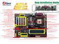
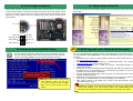
SYSFAN3 Connector
Die-Hard BIOS 1 and BIOS 2
(For AX4C-G, AX4C Max)
(AX4C PRO, User Upgrade Optional)
IrDA Connector
Front Panel Connecto
r
FDD Connector
Supports 2
n
d
USB (2.0) Connecto
r
JP14 CMOS Clear Jumper
Resetable Fuse
478-pin CPU socket with Voltage and
Frequency Auto-detection that supports
Intel
®
Pentium
®
4 CPU
32-bit PCI Expansion Slot x5
CPUFAN1 Connector with H/W
Monitoring Function
184-pin DIMMx3 supports Dual
Channel DDR400/DDR333
(Max. to 4GB)
Intel
®
875P and ICH5 chipsets
ICH5R (AX4C Pro, AX4C Max)
ICH5 (AX4C-G)
3300μF Low ESR Capacitors
ATX Power Connector
CD-IN Connecto
r
(AX4C Pro, AX4C Max only)
Dr. LED Connector
O
n
b
oar
d
AC
’
9
7
CODE
C
(AX4C Pro, AX4C Max only)
Chassis Intrusion Connector
Front Audio Connecto
r
(AX4C Pro, AX4C Max only)
JP28 Keyboard/Mouse Wakeup
Enable/Disable Jumper
Promise ATA133 IDE Connector x1
(
AX4C Max onl
y)
S/PDIF Connecto
r
(AX4C Pro, AX4C Max only)
WOL (Wake on LAN) Connector
SYSFAN2 Connector
Broadcom 10/100Mbps LAN Chip
(For AX4C Pro only)
Broadcom Gigabit PCI LAN Chip
(For AX4C Max only)
4-pin 12V. ATX Power Connector
AGP slot
(For 1.5V AGP card only)
AU
X
-IN Connecto
r
(
AX4C Pro
,
AX4C Max onl
y)
GAME Connector
(Slot 5: Self-Powered PCI card that
supports high power-consuming PCI cards)
Serial ATA Ports x 4
(AX4C Max with RAID 0, 1, 0+1)
(AX4C Pro with RAID 0, 1 only)
JP2
D
r.
V
o
i
ce
O
utput
S
e
l
ect
J
umpe
r
(AX4C Pro, AX4C Max only)
ATA33/66/100 IDE Connector x2
PS/2 Mouse
Connector
PS/2 Keyboard
Connector
USB Port
(2.0)
SPP/EPP/ECP
Parallel Port
COM 1 Port
COM 2 Port
RJ45 LAN Jack
(AX4C Pro, AX4C Max only
Line-In
Speaker Out
MIC-In
USB Port
(2.0)
STBY LED
BOOT LED
AOpen reserves the right to revise all the specifications and information contained in this documentation, which are subject to change without notice.
WOM (Wake on MODEM) Connector
IEEE1394 Connecto
r
s x2
(
AX4C Max onl
y)
AGP LED
JP24 DieHard BIOS Rescue Jumper

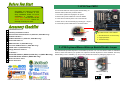
1. JP14 Clear CMOS
Everything you need to boot this
motherboard is included in this
Easy Installation Guide. For more
information, a complete Online
User's Manual can be found in the
Bonus Pack CD Disc. Thanks for
the hel
p
of savin
g
our earth.
PART NO: 49.8AU01.EE1 DOC. NO: AX4CMAX-EG-E0312B
You can clear CMOS to restore system default setting. To
clear the CMOS, follow the procedure below.
1. Turn off the system and unplug the AC power.
2. Remove ATX power cable from connector PWR2.
3. Locate JP14 and short pins 2-3 for a few seconds.
4. Return JP14 to its normal setting by shorting pin 1 & pin 2.
5. Connect ATX power cable back to connector PWR2.
Tip: When should I Clear CMOS?
1. Boot fail because of overclocking…
2. Forget password…
3. Troubleshooting…
This Motherboard x1
This Easy Installation Guide x1
Enhanced Full Pictured Manual x1 (AX4C Pro, AX4C Max only)
EzRestore Guide x 1
40-Wire IDE Cable x 1 (AX4C Pro, AX4C Max only)
80-wire IDE Cable x1
IEEE1394 Cable x1 (AX4C Max only)
Two Ports USB2.0 Cable x 1 (AX4C Max only)
S/PDIF Cable x1 (AX4C Max only)
Floppy Disk Drive Cable x1
IO Shield x 1
Serial ATA Cable x1 (AX4C-G, AX4C Pro), x2 (AX4C Max only)
Serial ATA Power Cable x1 (AX4C Max only)
Norton Anti-Virus CD x 1
Bonus Pack CD x1
Pin 1
2. JP28 Keyboard/Mouse Wake-up Enable/Disable Jumper
This motherboard provides keyboard / mouse wake-up function. You can use JP28 to enable or disable this
function, which could resume your system from suspend mode with keyboard or mouse installed. The factory
default setting is set to “Disable”(1-2), and you may enable this function by setting the jumper to 2-3.
JP28
KB/Mouse Wake-up
Normal Operation
(default)
1
Clear CMOS
1
Pin 1
Enable
Disable
(Default)
Pin 1

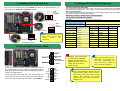
Plug in the CPU fan cable to the 3-pin CPUFAN1 connector. If you have chassis fan, you
can also plug it on SYSFAN2 or SYSFAN3 connector.
CPU Ratio 8x, 9x, 10x… 21x, 22x, 23x…39x
CPU FSB
133~ 200MHz
IMHz Stepping CPU Overclocking
100~ 400MHz
Northwood CPU CPU Core Frequency FSB Clock System Bus Ratio
Pentium 4 1.6G 1600MHz 133MHz 533MHz 12x
Pentium 4 1.7G 1700MHz 133MHz 533MHz 13x
Pentium 4 2.26G 2260MHz 133MHz 533MHz 17x
Pentium 4 2.4G 2400MHz 133MHz 533MHz 18x
Pentium 4 2.53G 2530MHz 133MHz 533MHz 19x
Pentium 4 2.66G 2660MHz 133MHz 533MHz 20x
Pentium 4 2.80G 2800MHz 133MHz 533MHz 21x
Pentium 4 3.0G 3000MHz 200MHz 800MHz 15x
Pentium 4 3.06G 3060MHz 133MHz 533MHz 23x
5. Setting CPU Voltage & Frequency
CPU Core Voltage Auto Detectable
This motherboard supports CPU VID function. The CPU core voltage will be automatically
detected and the range is from 1.1V to 1.925V. It is not necessary to set CPU Core Voltage.
Setting CPU Frequency
This motherboard is CPU jumper-less design, you can set CPU frequency through the BIOS
setup, and no jumpers or switches are needed.
BIOS Setup > Frequency / Voltage Control > CPU Speed Setting
Core Frequency = CPU FSB Clock * CPU Ratio
Note: Some CPU fans do not
have sensor pin so they
cannot support fan
monitoring.
CPUFAN1 Connector
Warning: Intel
®
875P chipset
supports maximum 800MHz
(200MHz*4) system bus and
66MHz AGP clock; higher clock
setting may cause serious
system damage.
3. Installing CPU & System Fan
SYSFAN2 Connector
FAN3 Connector
GND
+12V
SENSOR
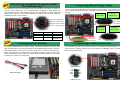
4. Connecting Front Panel Cable
Attach the power LED, speaker, and reset switch connectors to
the corresponding pins. If you enable “Suspend Mode” item in
BIOS Setup, the ACPI & Power LED will keep flashing while the
system is in suspend mode.
Locate the power switch cable from your ATX housing. It is
2-pin female connector from the housing front panel. Plug this
connector to the soft-power switch connector marked SPWR.
Note: Since the latest processor,
Northwood, would detect the
clock ratio automatically, you
may not be able to adjust the
clock ratio in BIOS manually.
SYSFAN3 Connector
1
SPWR
GND
ACPI LED-
GND
ACPILED
NC
ACPI_B
GND
RESET
GND
NC
NC
+5V
IDE LED
IDE LED
+5V
+5V
GND
NC
SPEAKER
1
Speaker
IDE LED
SPWR
ACPI & PWR
LED
Reset
ACPI LED (BLUE)
GND
+12V
SENSOR
GND
SENSOR
+12V
Tip: The North Bridge of Canterwood does
supports “Turbo mode”, which is used to
lower latency paths from FSB to system
memory that enhances the system
performance, when it is set at FSB800 and
DDR400 mode.

Primary
Master (1st)
Primary
Slave (2nd)
Secondary
Slave (4th)
Secondary
Master (3rd)
Pin 1
Pin 1
Motherboard SATA 1 & 2 SATA 3 & 4
AX4C-G RAID 0
AX4C Pro RAID 0
AX4C Max RAID 0 RAID 0, 1, 0+1
(With ATA133)
Serial ATA Ports
SATA port 1 (ICH5, ICH5R)
SATA port 2 (ICH5, ICH5R)
SATA port 3 (PDC20378)
SATA port 4 (PDC20378)
8. Connecting IDE and Floppy Cables
Connect 34-pin floppy cable and 40-pin, 80-wire IDE cable to floppy connector FDC and
IDE connector. Be careful of the pin1 orientation. Wrong orientation may cause system
damage.
Pin 1
ATA 33/66/100
IDE Connector
IDE 1 (Primary)
IDE 2 (Secondary)
This motherboard provides eight USB2.0 connectors. Compared to traditional USB 1.0/1.1
with the speed of 12Mbps, USB 2.0 has a fancy speed up to 480Mbps, which is 40 times
faster than the traditional one.
USB2 Connector
Pi
n
1
9. Support Eight USB2.0 Connectors
6. Serial ATA Supported (With RAID support on AX4C
Pro, AX4C Max only)
This motherboard comes with integrated Serial ATA controller in chip, aiming to provide you
an even faster transfer rate of 150 Mbytes/second. Integrated in North Bridge, this
motherboard also comes along with RAID function that supports RAID 0, while AX4C MAX
supports extra RAID 0+1 with Promise PDC20378 by ATA133 IDE connector. Please be
noted that Hot-Plug in is not allowed.
7. Connecting Serial ATA Disk
To connect a Serial ATA disk, you have to have a 7-pin serial ATA cable. Connect two ends
of the serial ATA cable to the serial ATA header on the motherboard and the disk. Like every
other traditional disk, you also have to connect a power cable. Please be noted that it is a
jumper free implement; you don’t need to set jumpers to define a master or slave disk.
When connecting two serial ATA disks, the system will automatically take the one connected
to “Serial ATA 1” header as a master disk.
Serial ATA cable
USB2 Connector
KEY
GND
SBD2+
SBD2
+5V
NC
GND-
SBD3+
SBD3-
+5V
1
FDD Connector
ATA 133
IDE Connector
(AX4C MAX only)

11. DieHard BIOS II (For AX4
C
-G, AX4C Max)
(AX4C Pro, User Upgrade Optional)
Many viruses have been found that they may destroy bios code and data area lately. This
motherboard implements a very effective hardware protection method without any software or
BIOS coding involved, therefore it is 100% virus free. You may restore the originally mounted
BIOS with 2
nd
BIOS ROM by setting JP24 to pin 2-3 if it fails to work properly.
12. Memory Module (128-Bit DDR Dual Channel)
10. S/PDIF (Sony/Philips Digital Interface) Connector
(AX4C Pro, AX4C Max only)
S/PDIF (Sony/Philips Digital Interface) is a newest audio transfer file format, which provides
impressive audio quality through optical fiber and allows you to enjoy digital audio instead of
analog audio. Normally there are two S/PDIF outputs as shown, one for RCA connector, the
most common one used for consumer audio products, and the other for optical connector
with better audio quality. Through a specific audio cable, you can connect the S/PDIF
connector to other end of the S/PDIF audio module, which bears S/PDIF digital output.
However, you must have a S/PDIF supported speaker/amplifier/decoder with S/PDIF digital
input to connect to the S
/
PDIF digital output to make the most out of this function.
Pin 1
+5V
NC
S/PDIFOUT
GND
S/PDIFIN
1
In the past, we used to have 64-bit memory bandwidth for memory access. No matter how
many memory modules have been installed, though capacity added, the speed of access
remains the same. With 128-bit dual channel introduced, it doubles the memory bandwidth
up to 5.4GB in advanced 128-bit mode. This motherboard supports DDR400/333 with
Maximum capacity up to 4GB.
13. Connect IEEE1394 Connector (AX4C Max only)
S/PDIF Module
(User Upgrade Optional)
S/PDIF
Cable
S/PDIF OUT
S/PDIF OUT
S/PDIF IN
S/PDIF IN
(Optical)
(RCA)
128-bit DDR Dual Channel
Memory module
With AGERE 1394 Control chip (with AGERE FW323), the IEEE 1394 provides data
transfer rate up to 400Mb/s, and USB just has 12Mbps. Hence, the IEEE 1394 interface
can connect with the devices that need high data transferring performance, such as digital
camera, scanner or others IEEE 1394 devices. Please use the proper cable to connect
with devices.
Pi
n
1
KEY
1394_PWR
TPB+
GND
TPA+
Shielding GND
1394_PWR
TPB-
GND
TPA-
2 1
10 9
JP24
BIOS 1
BIOS 2
(AX4C PRO -User
Upgrade Optional)
Rescue
1
Normal
(Default)
1

After you finish the setting of jumpers and connect correct cables. Power on
and enter the BIOS Setup, press <Del> during POST (Power On Self Test).
Choose "Load Setup Defaults" for recommended optimal performance.
Warning: The upgrade of new BIOS will permanently replace your original BIOS
content after flashing. The original BIOS setting and Wi2000/WinXP PnP
information will be refreshed and you probably need to re-configure your system.
14. Front Audio Connector
15. Power-on and Load BIOS Setup
17. BIOS Upgrade under Windows Environment
You may accomplish BIOS upgrade procedure with EzWinFlash by the following steps,
and it’s STRONGLY RECOMMENDED to close all the applications before you start the
upgrading.
1. Download the new version of BIOS package zip file from AOpen official web site.
(ex: http://english.aopen.com.tw)
2. Unzip the download BIOS package (ex: WAX4CMAX102.ZIP) with WinZip
(http://www.winzip.com) in Windows environment.
3. Save the unzipped files into a folder, for example, WAX4CMAX102.EXE &
WAX4CMAX102.BIN.
4. Double click on the WAX4CMAX102.EXE, EzWinFlash will detect the model name
and BIOS version of your motherboard. If you had got the wrong BIOS, you will not
be allowed to proceed with the flash steps.
5. You may select preferred language in the main menu, then click [Start Flash] to start
the BIOS upgrade procedure.
6. EzWinFlash will complete all the process automatically, and a dialogue box will pop
up to ask you to restart Windows. You may click [YES] to reboot Windows.
7. Press <Del> at POST to enter BIOS setup, choose "Load Setup Defaults", then
“Save & Exit Setup”. Done!
16. AOpen Bonus Pack CD
You can use the autorun menu of Bonus CD disc. Choose the utility and driver and select
model name.
Del
Warning: Please avoid of using "Load
Turbo Defaults", unless you are sure
your system components (CPU, DRAM,
HDD, etc.) are good enough for turbo
settin
g
.
If the housing has been designed with an audio port on the front panel, you’ll be able to
connect onboard audio to front panel through this connector. By the way, please remove
5-6 and 9-10 jumper caps from the Front Audio Connector before connecting the cable.
Please do not remove these 5-6 and 9-10 yellow jumper caps if there’s no audio port on
the front panel.
Pin 1
AUD_MIC
AUD_MIC_BIAS
AUD_FPOUT_R
NC
AUD_FROUT_L
AUD_GND
AUD_VCC
AUD_RET_R
KEY
AUD_RET_L
9 10
1 2

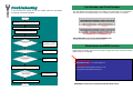
If you encounter any trouble to boot you system, follow the procedures
accordingly to resolve the problem.
Part Number and Serial Number
The Part Number and Serial number are printed on bar code label. You can find this
bar code label on the outside packing, or on component side of PCB. For example:
Model name and BIOS version
AX4C Max R1.00 Feb. 01. 2003 AOpen Inc.
Award Plug and Play BIOS Extension v1.0A
Copyright © 1998, Award Software, Inc.
Model name and BIOS version can be found on upper left corner of first boot screen
(POST screen). For example:
AX4C Max is model name of motherboard; R1.00 is BIOS version
P/N: 91.88110.201 is part number, S/N: 919493Web Site:
Part No. Serial No.
Part No.
Serial No.
Make sure if the jumper settings for CPU and DRAMs are correct.
Clear CMOS, then plug the ATX power cord correctly.
(For P4 system, please also plug the 4pin(+12V) cord.
Install the VGA card. Then connect your monitor and keyboard.
The problem was probably caused
by power supply or motherboard
failure. Please contact your reseller
or local distributor for repairing.
Perhaps your VGA card or monitor
is defective.
No
Yes
No
Yes
It is very possible that your keyboard
is defective.
During system rebooting, press Del to enter BIOS Setup. Choose
“Load Setup Default".
The problem should be caused by the
IDE cables or HDD itself.
Re-install Windows 95, Windows 98 or Windows NT.
Yes
Yes
Turn off the power and unplug the AC power cable, then remove all
of the addon cards and cables, including VGA, IDE, FDD, COM1,
COM2 and Printer.
Turn on the power, and check if
the power supply and CPU fan
work properly.
Start
Check if there is display.
Press Ctrl, and Alt key at the
same time, hold them and then
press Del to see if the
s
y
stem
r
eboots.
Turn off the system and
re-connect the IDE cable.
Check if the system can
reboot successfully.
End
No
No

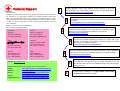
Dear Customer,
Thanks for choosing AOpen products. To provide the best and fastest service to
our customer is our first priority. However, we receive numerous emails and
phone-calls worldwide everyday, it is very hard for us to serve everyone on time.
We recommend you follow the procedures below and seek help before contact
us. With your help, we can then continue to provide the best quality service to
more customers.
Thanks very much for your understanding!
AOpen Technical Supporting Team
Online Manual: To download manual, please log on and then select your
preferred language. Under “Type” directory, choose “Manuals” to go to our
manual database. You can also find the manual and EIG in AOpen Bonus Pack.
http://download.aopen.com.tw/downloads
1
1
Test Report: We recommend you to choose board/card/device from the
compatibility test reports for assembling your PC. It may prevent incompatibility
problems.
http://english.aopen.com.tw/tech/report/default.htm
2
2
FAQ: Here we list problems that users often encounter and FAQ
(Frequently Asked Questions). You may select your preferred language
after log on, and may be able to find a solution to your problem.
http://club.aopen.com.tw/faq/
5
5
Download Software: After log on and having language selected, you may
get the latest updated BIOS/utility and drivers you need under “Type”
directory. In most case, newer versions of drivers and BIOS have solved
earlier bugs or compatibility problems.
http://download.aopen.com.tw/downloads
3
3
eForum: AOpen eForum is provided to discuss our products with other users, in
which your problem probably had been discussed before or will be answered.
After log on, you may select your preferred language under “Multi-language”.
http://club.aopen.com.tw/forum/
4
4
Contact Distributors/Resellers: We sell our products through resellers
and integrators. They should know your system configuration very well
and should be able to solve your problem efficiently and provide important
reference for you.
6
6
Contact Us: Please prepare detail system configuration and error
symptom before contacting us. The part number, serial number
and BIOS version are also very helpful.
7
7
Web Site: www.aopen.com
E-mail: Send us email by going through the contact form below.
English http://english.aopen.com.tw/tech/default.htm
Japanese http://aopen.jp/tech
Chinese http://www.aopen.com.tw/tech/default.htm
German http://www.aopencom.de/tech/default.htm
Simplified Chinese http://www.aopen.com.cn/tech/default.htm
Pacific Rim
AOpen Inc.
Tel: 886-2-3789-5888
Fax: 886-2-3789-5899
America
AOpen America Inc.
Tel: 1-408-232-1200
Fax: 1-408-232-1280
Europe
AOpen Computer b.v.
Tel: 31-73-645-9516
Email:[email protected]
Germany
AOpen Computer GmbH.
Tel: 49-2131-1243-710
Fax: 49-2131-1243-999
China
艾爾鵬國際貿易(上海)有限公
司
Tel: 86-21-6225-8622
Fax: 86-21-6225-7926
Japan
AOpen Japan Inc.
Tel: 81-048-290-1800
Fax: 81-048-290-1820
-
 1
1
-
 2
2
-
 3
3
-
 4
4
-
 5
5
-
 6
6
-
 7
7
-
 8
8


AOpen AX4C-G Easy Installation Manual
- Type
- Easy Installation Manual
Ask a question and I''ll find the answer in the document
Finding information in a document is now easier with AI
Related papers
-
AOpen AX4C Pro Online Manual
-
-
-
-
-
-
-
-
-
