Page is loading ...

GE
Lighting
Installation Guide
imagination at work
BEFORE YOU BEGIN
Read these instructions completely and carefully.
FOR USE WITH CEILING MOUNTED TRACK ONLY.
READ JUNO TRACK INSTALLATION INSTRUCTIONS
FOR GUIDELINES ON TRACK INSTALLATION.
WARNING
RISK OF ELECTRIC SHOCK
Turn power off before inspection, installation or removal.
CAUTION
To reduce risk of re and electric shock, use only with
Juno single circuit track system.
IMPORTANT SAFETY INSTRUCTIONS
When installing or using this track system, basic safety
precautions should always be followed, including the
following:
a) Read all instructions
b) Do not install this track in damp or wet locations.
c) Do not cut any track sections.
d) Do not install any part of a track system less than
5 feet above the oor.
e) Do not install any luminaire assembly closer than
6 inches from any curtain, or similar combustible material.
f) Disconnect electrical power before adding to or
changing the conguration of the track.
g) Do not attempt to energize anything other than
lighting track luminaires on the track. To reduce the risk
of re and electric shock, do not attempt to connect
power tools, extension cords, appliances, and the like to
the track.
h) Do not connect a track to more than one branch
circuit unless the track is constructed so that it can be
used with more than one branch circuit. Check with a
qualied electrician. Although the track lighting system
may seem to operate acceptably, a dangerous overload
of the neutral may occur and result in a risk of re.
SAVE THESE INSTRUCTIONS
For future reference when adding xtures
or changing the track conguration.
(TS Series)
Lumination
TM
LED Track Light

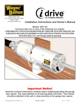
Fixture Installation - Single Circuit Track
Fixture Installation - Two Circuit Track
Hold the adapter below the
track with your thumb on the
spring loaded locking tab. Ensure
locking tab is positioned directly
below the polarity line. Push
adapter into track.
For Two Circuit installation, the
“Positive Contact” (marked “P”)
must be in raised position. Raise
“Positive Contact” by inserting
a thin screwdriver under the
contact and lifting upward.
Rotate adapter 1/4 turn (90°)
clockwise.
Insert a “Contact Support”
under the raised “Positive
Contact”. These Positive Contact
Supports are supplied with all
Juno Two Circuit Track sections.
Release the locking tab and the
xture should snap into position.
Turn the xture on by the switch.
To attach xture to Track,
proceed the same as with “Single
Circuit Track” attachment.
2
2
3
3
This device complies with Part 15 of the FCC Rules. Operation is subject to the following two conditions: (1) This device may not cause harmful interference,
and (2) this device must accept any interference received, including interference that may cause undesired operation. This Class [B] RFLD complies with the
Canadian standard ICES-003. Ce DEFR de la classe [B] est conforme á la NMB-003 du Canada.
Note: This equipment has been tested and found to comply with the limits for a Class B digital device, pursuant to part 15 of the FCC Rules. These limits are
designed to provide reasonable protection against harmful interference when the equipment is operated in a commercial environment. This equipment
generates, uses, and can radiate radio frequency energy and, if not installed and used in accordance with the instruction manual, may cause harmful
interference to radio communications. Operation of this equipment in a residential area is likely to cause harmful interference in which case the user will be
required to correct the interference at his own expense.
1
1
IND130-100914
GE Lighting • 1-888-MY-GE-LED (1-888-69-43-533) • www.gelighting.com
GE Lighting Solutions, LLC is a subsidiary of the General Electric Company. The GE brand and logo are trademarks of the General Electric Company.
© 2014 GE Lighting Solutions, LLC. Information provided is subject to change without notice. All values are design or typical values when measured under laboratory conditions.
Fixture intended for commercial use only. Use only in non-insulated applications.
Contact Support
Positive Contact in raised postionPositive Contact
Adapter switch
Tab snaps
into track
Lift with screwdriver
Align locking tab
with polarity line
Rotate
Track
/