Page is loading ...

CENTRALE DI COMANDO
CONTROL UNIT
STEUEREINHEIT
CENTRALE DE COMMANDE
CENTRAL DE MANDO
CENTRALKA STEROWANIA
L8542078
Rev. 05/06/03
Libro istruzioni
Operating instructions
Betriebsanleitung
Livret d’instructions
Manual de instrucciones
Książeczka z instrukcjami
UNIONE NAZIONALE COSTRUTTORI
AUTOMATISMI PER CANCELLI, PORTE,
SERRANDE ED AFFINI

2
191817161514
3837
11
10
9
8
7
6
5
1312
4
F3
0.315AT
F2
6,3A
F1
1AT
F5
5A
F4
5A
230Vac
50Hz
NL
RADIO
LAMP
230Vac
TLS
27
26
25
24
23
22
21
2928
30
31
20 32
33
34
35
36
DAS
J2 DAS
Open
DAS N.C.
J2 DAS
Close
DAS 8K2
8k2
DAS
SWO-M1 (Open)
SWC-M1 (Close)
SWO-M2 (Open)
SWC-M2 (Close)
P.P.
COM
COM
PED.
OPEN
CLOSE
PHOT
PHOT (Close)
STOP
SHIELD
ANT
ANT
3837
RX
2 CH.
SCA 24Vac
3W max
24Vac
500mA max
Lock
12Vac
10W
0V
12V
COM
M1
C
COM
M2
C
191817161514
191817161514

8
9
BRAIN control unit
The BRAIN electronic control unit may be used for the control of 1 or 2 motors with power not higher than 500W+500W.
GENERAL WARNINGS
a) The electrical installation and the operating logic must comply with the regulations in force.
b) The leads fed with different voltages must be physically separate, or they must be suitably insulated with additional insulation of
at least 1 mm.
c) The leads must be secured with an additional fixture near the terminals.
d) Check all the connections again before switching on the power.
e) The unused N.C. inputs must be bridged.
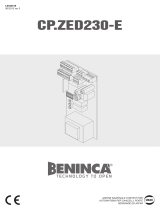
INPUT/OUTPUT FUNCTIONS
BRAIN Control unit
N° Terminals Function Description
1-2-3 Power supply Input 230Vac 50Hz (1-GND/2-Phase/3-Neutral)
4-5-6 Motor 1 Connection of motor 1: (4-start/5-Com/6-start)
7-8-9 Motor 2 Connection of motor 2: (7-start/8-Com/9-start)
10-11 Blinking light Connection of blinking light 230Vac 40W max.
12-13 TLS
N.O. clean contact for courtesy light, timer, etc.
The activation time is regulated by the parameter TLS
14-15 24 Vac Accessories power supply output 24Vac/0.5A max.
16-17 Lock 12Vac Accessories power supply output 12Vac/10W for electric lock (16:0V, 17:+12V)
18-19 SCA N.O. clean contact for gate open warning light.
20-21 EDGE
Input, sensitive edge contact
Resistive edge: “DAS” Jumper closed
Mechanical edge: “DAS” Jumper open
When the edge is activated, the gate movement is stopped and reversed for about 3s.
22 SWO-M1 OPEN limit switch input motor 1 (N.C contact.)
23 SWC-M1 CLOSE limit switch input motor 1 (N.C. contact)
24 SWO-M2 OPEN limit switch input motor 2 (N.C. contact)
25 SWC-M2 CLOSE limit switch input motor 2 (N.C. contact)
26-27 COM Common for limit switch and all the control inputs.
28 Step-by-Step Step-by-Step button input (N.O. contact)
29 PED Pedestrian button input (N.O. contact)
30 OPEN OPEN button input (N.O. contact), configurable as Clock contact
31 CLOSE CLOSE button input (N.O. contact)
32 PHOT Active photocell input on opening and closing
33 PHOT CLOSE Active photocell input only on closing
34 STOP STOP button input (N.C. contact)
35-36 Antenna
Antenna connection for plug-in radio receiver board (35-screen/36-signal).
37-38 RX 2ch.
Second radio channel output of the plug-in receiver.
Voltage-free N.O. contact.
J3 Radio Plug-in connector for radio receiver.
Notes:
The EDGE must be connected exclusively to the special inputs 20/21. Two types of EDGE may be used:
If an edge with resistance 8K2 is used, close the Jumper “DAS”.
If a mechanical edge with N.C. contact is used, open the Jumper “DAS”.
If the edge is not used, bridge the terminals 20-21 and open the Jumper “DAS”.

10
11
Programming
The programming of the various functions of the control unit is carried out using the LCD display on the control unit and setting
the desired values in the programming menus described below.
The parameters menu allows you to assign a numerical value to a function, in the same way as a regulating trimmer.
The logic menu allows you to activate or deactivate a function, in the same way as setting a dip-switch.
Other special functions follow the parameters and logic menus and may vary depending on the type of control unit or the software
release.
To access programming:
1 – Press the button <PG>, the display goes to the first menu, Parameters “PAR”.
2 – With the <+> or <-> button, select the menu you want.
3- Press the button <PG>, the display shows the first function available on the menu.
4 - With the <+> or <-> button, select the function you want.
5 - Press the button <PG>, the display shows the value currently set for the function selected.
6 - With the <+> or <-> button, select the value you intend to assign to the function.
7 - Press the button <PG>, the display shows the signal “PRG” which indicates that programming has been completed.
Notes:
Simultaneously pressing <+> and <-> from inside a function menu allows you to return to the previous menu without making any
changes.
Simultaneously pressing <+> and <-> when the display is switched off shows the card software release.
Hold down the <+> key or the <-> key to accelerate the increase/decrease of the values.
After waiting 60s the control unit quits programming mode and switches off the display.
Parameters, Logic and Special Functions
The tables below describe the individual functions available in the control unit.
MENU FUNCTION
Settable values
MIN-MAX-(Default)
MEMO
PARAMETERS
TCA
Automatic closing time. Active only with logic “TCA”=ON.
At the end of the set time the control unit orders a closing manoeuvre.
1-240-(40s)
TM1
Motor 1 work time. Regulates the maximum duration of the opening and clos-
ing manoeuvre of the motor 1.
It must be set about 4 sec. longer than the actual travel time of the automatism.
5-180-(24s)
TM2
Motor 2 work time. Regulates the maximum duration of the opening and clos-
ing manoeuvre of the motor 2.
It must be set about 4 sec. longer than the actual travel time of the automatism.
5-180-(24s)
TPed
Pedestrian opening time.
Regulates the duration of the pedestrian opening manoeuvre of the motor 1.
5-180-(10s)
PM1
Motor 1 torque. Regulates the torque applied on the motor 1.
RESPECT THE REGULATIONS IN FORCE!
1-99-(40%)
PM2
Motor 2 torque. Regulates the torque applied on the motor 2.
RESPECT THE REGULATIONS IN FORCE!
1-99-(40%)
TDMo
Mot.2 opening delay time.
Regulates the delay time of motor 2 on opening with respect to motor 1
0-15-(2s)
TDMC
Mot.1 closing delay time
Regulates the delay time of motor 1 on closing with respect to motor 2
0-40-(3s)
TLS
TLS contact activation time.
At each manoeuvre the contact closes for the set time.
1-240-(60s)
TLOc
Electric lock activation time. If the electric lock is not used, set the parameter at
0.
0-5-(3s)
TsM1
Motor 1 slowing time
Regulates the duration of the slowing phase of motor 1 on opening and clos-
ing. The set time is subtracted from the motor 1 work time (TM1), which must
always be higher.
1-30-(7s)
TsM2
Motor 2 slowing time
Regulates the duration of the slowing phase of motor 2 on opening and clos-
ing. The set time is subtracted from the motor 2 work time (TM2), which must
always be higher.
1-30-(7s)
Psl1
Motor 1 slowing torque
Regulates the torque applied to motor 1 during the slowing phase
1-99-(70%)
Psl2
Motor 2 slowing torque
Regulates the torque applied to motor 2 during the slowing phase
1-99-(70%)

10
11
MENU FUNCTION
Settable values
ON-OFF-(Default)
MEMO
LOGIC
TCA
Enables or disables automatic closing
On: automatic closing enabled
Off: automatic closing disabled
(ON)
IbL
Enables or disables condominium function.
Off: condominium function disabled.
On: condominium function enabled. The step-by-step impulse or transmitter
impulse has no effect during the opening phase.
(OFF)
SCL
Enables or disables rapid closing
On: rapid closing enabled. With the gate open or in the opening phase the
intervention of the photocell causes automatic closing after 3 s. Active only with
TCA:ON.
Off: rapid closing disabled.
(OFF)
Sld
Enables or disables slowing.
On: Slowing active.
Off: Slowing excluded.
(OFF)
PP
Selects the operating mode of the ”Step by step button” and of the transmitter.
On: Operation: OPEN > CLOSE > OPEN >
Off: Operation: OPEN > STOP > CLOSE > STOP >
(OFF)
PRE
Enables or disables pre-blinking.
On: Pre-blinking enabled. Blinking is activated 3s before the motor starts.
Off: Pre-blinking disabled.
(OFF)
HAM
Enables or disables the inversion stroke function
On: Function enabled. Before each opening or closing manoeuvre the control
unit orders a manoeuvre of 2s in the opposite direction to facilitate the release
of the electric lock.
Off: Function disabled.
(OFF)
BLC
Enables or disables the block maintaining function.
Recommended for hydraulic motors to keep the leaf resting against the me-
chanical stop block.
On: Block maintaining function enabled. Every 2 hours the control unit makes a
closing manoeuvre with a duration of about 3s to keep the leaf in contact.
Off: Block maintaining function disabled.
(OFF)
SPN
Enables or disables starting torque function.
On: Starting torque enabled. At the start of each manoeuvre for 2s the motor
operates at maximum torque.
Off: Starting torque disabled.
(ON)
LTCA
Selects the operating mode of the blinking light during the time TCA
On: Blinking light on during TCA
Off: Blinking light off during TCA
(OFF)
CLOC
Selects the mode of the OPEN input
On: OPEN input with CLOCK function.
To be used for connection to a timer for timed opening/closing. (Contact
CLOSED- gate open, Contact open, normal operation).
(OFF)
htr
Enables or disables Man present function.
On: Man Present operation.
The OPEN/CLOSE buttons must be held down during the whole manoeuvre.
Off: Automatic operation.
(OFF)
mloc
Selects the type of electric lock used.
On: Magnetic electric lock, normally fed at 12Vac.
Before each opening manoeuvre the power supply is interrupted for the time
set by the parameter TLOC.
Off: Electric lock with latch, normally not fed.
Before each opening manoeuvre power is fed at 12Vac for the time set by the
parameter TLOC.
(OFF)

12
13
MENU FUNCTION
Settable values
ON-OFF-(Default)
MEMO
LOGIC
1mot
Select the 1/2 motors operating mode:
On: only one motor (motor 1) active. Function to be used in the following cases:
- for single motor, to connect M1:4-5-6.
- for two syncronized motors (for instance overhead door), to connect M1:4-5-6
and M2:7-8-9. You need to regulate the parameters related to the motor 1, the
limit switch entries M2 are disarmed (not activate).
Off: Both motors operating.
(OFF)
not
The calculation of residual operating time is activated or deactivated in the
event of partial operations:
On: Calculation of deactivated time. In case of partial operations, the opera-
ting time is reset. The following operation restarts for the entire time preset by
parameter TM1/TM2.
Off: Calculation of activated time. In case of partial operations, the operating
time is stored in memory and then subtracted from the TM1/TM2 parameter
value in the following operation.
(ON)
MENU FUNCTION
RES
RESET of the control unit. ATTENTION!: Returns the control unit to the default values.
Pressing the <PG> button for the first time causes blinking of the letters RES, pressing the <PG> button
again resets the control unit.
NMAN
Displays the number of complete cycles (open+close) carried out by the automation.
When the <PG> button is pressed for the first time, it displays the first 4 figures, the second time it shows the
last 4. Example <PG> 0012 >>> <PG> 3456: made 123.456 cycles.
Example of programming
Let us suppose it is necessary to:
- set an automatic closing time (TCA) of 100s
- activate pre-blinking
Perform the operations described below step by step:
Step Press Display Notes
1
PAR
First menu
2
TCA
First function of the first menu
3
040
Value currently set for the function selected
4
100
Set the desired value with the <+> and <-> keys
5
PRG
The value is programmed
TCA
When programming has been made, the display goes to the function just set
6
PAR
Press <+> and <-> simultaneously to go to the higher menu
7
Log
Second menu
8
TCA
First function of the second menu
9
Pre
Press <-> several times to select PRE logic
10
OFF
Value currently set for the function selected
11
ON
Set the desired value with the <+> and <-> keys
12
PRG
The value is programmed
Pre
When programming has been made, the display goes to the function just set
13
PAR
Press <+> and <-> simultaneously to go to the higher menu and quit programming or wait
30s.

12
13
Diagnostics
In the event of malfunctions, by pressing key + or - the status of all inputs (limit switches, control and safety) can be displayed. One
segment of the display is linked to each input. In the event of failure it switches on according to the following scheme.
N.C. inputs are represented by the vertical segments. N.O. inputs are represented by the horizontal segments.
For example, with the leaves
completely closed the display
is as follows:
the moment an Open impulse
is given:
during the opening phase: with the leaves completely
open:

/