Page is loading ...

ZWN6310 Z-Wave Water Leak Sensor
FCC Caution.
This device complies with part 15 of the FCC Rules. Operation is subject to the following two
conditions: (1) This device may not cause harmful interference, and (2) this device must accept any
interference received, including interference that may cause undesired operation.
Any Changes or modifications not expressly approved by the party responsible for compliance could
void the user's authority to operate the equipment.
Note: This equipment has been tested and found to comply with the limits for a Class B digital device,
pursuant to part 15 of the FCC Rules. These limits are designed to provide reasonable protection
against harmful interference in a residential installation. This equipment generates uses and can
radiate radio frequency energy and, if not installed and used in accordance with the instructions, may
cause harmful interference to radio communications. However, there is no guarantee that interference
will not occur in a particular installation. If this equipment does cause harmful interference to radio or
television reception, which can be determined by turning the equipment off and on, the user is
encouraged to try to correct the interference by one or more of the following measures:
-Reorient or relocate the receiving antenna.
-Increase the separation between the equipment and receiver.
-Connect the equipment into an outlet on a circuit different from that to which the receiver is
connected.
-Consult the dealer or an experienced radio/TV technician for help.
IC Caution.
- English:
This device complies with Industry Canada licence-exempt RSS standard(s).
Operation is subject to the following two conditions: (1) This device may not cause interference, and
(2) This device must accept any interference, including interference that may cause undesired
operation of the device.
- French:
Le présentappareilestconforme aux CNR d'Industrie Canada applicables aux appareils radio exempts
de licence. L'exploitationestautorisée aux deux conditions suivantes:
(1) l'appareil ne doit pas produirede brouillage, et
(2) l'utilisateur del'appareildoit accepter tout brouillageradioélectriquesubi, mêmesile
brouillageest susceptible d'encompromettre lefonctionnement.
Z-Wave Water Leak Sensor
Radiation Exposure Statement
The device has been evaluated to meet general RF exposure requirement. The device can be usedin portable exposure condition without restriction.
L'appareil a été évalué pour répondre aux exigences générales d'exposition aux radiofréquences. L'appareil peut être utilisé en condition d'exposition portable sans restriction.
This equipment should be installed and operated with minimum distance 0cm between the radiator & your body.
Cet équipement doit être installé et utilisé à une distance minimale de 0 cm entre le radiateur et votre corps
WARRANTY
Show Home Products warrants this product to be free from manufacturing defects for
a period of two years from the original date of consumer purchase. This warranty is limited
to the repair or replacement of this product only and does not extend to consequential or
incidental damage to other products that may be used with this product.
This warranty is in lieu of all other warranties, expressed or implied. Some states do not
allow limitations on how long an implied warranty lasts or permit the exclusion or limitation
of incidental or consequential damage, so the above limitations may not apply to you.
This warranty gives you specific rights, and you may also have other rights which vary from
state to state. if the unit should prove defective within the warranty period.
SPECIFICATIONS
Model:81018
Power supply: battery CR2*1PC
Signal (Frequency): 908.42 MHz.
Operating Range: Up to 100 feet line of sight
Operating Temp.: -15°C~60°C(5°F ~140°F)
Sleeping Mode current: 8uA max @DC3.0V
Transmitting Mode current: 34mA max @DC 3.0V
(20ms/1time)
Wireless Controller and the closest Z-Wave
receiver module.
Specifications subject to change without notice
due to continuing product improvement
WARNING
RISK OF FIRE
RISK OF ELECTRICAL SHOCK
RISK OF BURNS
CONTROLLING APPLIANCES:
EXERCISE EXTREME CAUTION WHEN USING Z-Wave
DEVICES TO CONTROL APPLIANCES. OPERATION
OF THE Z-Wave DEVICE MAY BE IN A DIFFERENT
ROOM THAN THE CONTROLLED APPLIANCE, ALSO AN
UNINTENTIONAL ACTIVATION MAY OCCUR IF THE WRONG
BUTTON ON THE REMOTE IS PRESSED. Z-Wave DEVICES
MAY AUTOMATICALLY BE POWERED ON DUE TO TIMED
EVENT PROGRAMMING. DEPENDING UPON THE APPLI-
ANCE, THESE UNATTENDED OR UNINTENTIONAL OP-
ERATIONS COULD POSSIBLY RESULT IN A HAZARDOUS
CONDITION. FOR THESE REASONS, WE RECOMMEND
DO NOT RETURN THIS PRODUCT TO THE STORE
THE FOLLOWING:
DO NOT USE Z-Wave DEVICES TO CONTROL ELECTRIC
HEATERS OR ANY OTHER APPLIANCES WHICH MAY PRES-
ENT A HAZARDOUS CONDITION DUE TO UNATTENDED OR
UNINTENTIONAL OR AUTOMATIC POWER ON CONTROL.

Important safeguards
Pre Cautions:
1. Do not attempt to disassemble the Shock Sensor, unless described in the user’s manual. There are no user serviceable
parts.
2. Handle with Care – Avoid striking or shaking.Improper use or storage could damage the Shock Sensor. Modifying or
tampering the device or its internal components can cause a malfunction
3. If you feel the Shock Sensor or any part of the Choice Alert system is not operating correctly or as described, please contact
Customer Service for assistance.
Safety and maintenance instruction
1. Make sure that all electric connections and connection cables meet the pertaining regulations and are in
conformity with the operating instruction.
2. Do not overload electrical outlets or extension cords, fire or electric shocks can be the result.
3. Please contact an expert in case you have any doubts about the mode of operation, the safety or connecting
the appliances.
4. Keep all parts away from young children’s reach.
5. Do not store this item on wet, very cold or warm places, this can damage the electronic circuit boards.
6. Avoid dropping or shocks, this can damage the electronic boards.
7. Never replace damaged power cables yourself! In such case, remove them from the net and take the devices to a workshop
Introduction
The Shock Sensor is designed to be used in areas where there is a Vibration or glass break detection, etc. When mounted
properly it can monitor whether Vibration happened.When Shock is detected, the Sensor will transmit a signal to the Control
Center. The Shock Sensor is recommended for use on the alert-only. If there is a shock, Zone will not sound an alarm but a
continuous alert until shock has stopped and vibration has dissipated.
The Shock Sensor is composed of two sections linked together with a cable The Sensor (transmitter) and the Probe. Before
installing, remove the White battery isolation tape from the Sensor. This activates the Lithium battery inside. The approximate
battery life is up to a year. When replacing batteries it is recommended to replace all batteries in a Zone at the same time in
order ensure proper operation of the entire system.
The Probe section will need to be mounted first. It is intendedto be positioned with the contacts pointing down. Find a suitable
location where water could accumulate if a leak were to occur (eg. along the baseboard of wall).You will need to determine if
the surface to mount the Probe is smooth or rough/porous. If smooth you can use one piece of the included double sided tape.
When using doublesided tape apply to clean dry surface.Remove one side ofthe tape and attach it tothe back side ofthe Probe.
Once the mounting surface is ready, remove the other side of the double side tape and position probe so that the metal contacts
are pointing down, touching the floor and the back ofthe Probe (with the double side tape) is up against the wall, baseboard or
mounting plate. Apply pressure to secure the Probe to the surface. If the mounting surface is rough or porous, you will need to
use the alternate mounting plate and screws (included). Secure the plate tothe desired location with the screws.
Note:
If postioning the probe to a metal surface, ensure the Probe’s contacts do not touch the metal surface.Next, stretch the
cable vertically and locate a suitable positionto mount the transmitter. Follow the same mounting instructions above for mounting
the transmitter.Once the Shock Sensor is mounted, you’ll need to assign it to a Zone on the Control Center.
The low battery status will be checked and reported per hour
A:Use certificated controller to remove device from network will reset it to factory default.
Please use this procedure only in the event that the network primary controller is missing or otherwise inoperable.
B: 1)power off
2 ) hold on 5 seconds when turn on the power of ZWN6310
1) Install the batteries. Visual indicator show status (RGB led flash - ready for adding, green flash- device added),
2) Make sure the device is located within direct range ofthe Z-Wave controller.
3) Follow the instructions of certified controller to include a devicefrom different manufactures into the Z-Wave network.
4) Once the controller is ready to include your device, triple click the Tamper switch in Flood Sensor.
5) Flood Sensor will be detected and added in the Z-Wave network.
1) Follow the instructions for your Z-Wave certified controller to exclude a device from the Z-Wave network.
2) Once the controller is ready to Exclude your device,triple click Tamper switch to exclude it from Z-Wave network.
1) Water Alarm(0x05) : Water leak detected Value=0x02
2) Home Security(0x07) : Tampering,product cover removed Value=0x03
1. The association group supports five nodes and lifeline function.
2. This product can be operated in any Z-Wave network with other Z-Wave certified devices from other manufacturers. All non-battery
operated nodes within the network will act as repeaters regardless of vendor to increase reliability of the network.

ZWN6310 supports 3 association groups. A maximum of 5 node ID’s (nonmulti-channel devices) can be assigned to these association groups.
Association group_1: Z-Wave Plus Lifeline Maximum 5 node
Association group_1 is default to associate with the primary controller (Gateway/Hub/Controller) for ZWN6310 Status change report,
Association group_2: basic set command
Association group_2 “Tamper” is assigned to the device status -Hall effect sensor (sends Basic Set command frames).
Association group_3: basic set command
Association Group_3 “On/Off” is assigned to the device status -Hall effect sensor (sends Basic Set command frames).
Include ZWN6310 to/from a Z-Wave Gateway with supporting Security the ZWN6310 can support the Primary Controller that
implemented the security S2.
Refer to your primary controller instructions to process the Secure Inclusion.The Below listed Command Class are
all supported the Security S2
z-wave protocol Command Class Node Info
supported Security S2 command classes
COMMAND_CLASS_SENSOR_BINARY,
COMMAND_CLASS_ASSOCIATION,
COMMAND_CLASS_MULTI_CHANNEL_ASSOCIATION_V2,
COMMAND_CLASS_ASSOCIATION_GRP_INFO,
COMMAND_CLASS_VERSION,
COMMAND_CLASS_ MANUFACTURER_ SPECIFIC,
COMMAND_ CLASS_ POWERLEVEL,
COMMAND_CLASS_BATTERY,
COMMAND_CLASS_NOTIFICATION_V8,
COMMAND_CLASS_WAKE_UP,
COMMAND_ CLASS_ SUPERVISION
COMMAND_CLASS_FIRMWARE_UPDATE_MD_V4
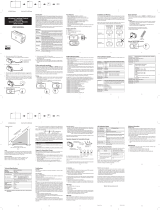
Package content
ZWN6310 Flood Sensor-1pcs
Bracket -1pcs
sensor-1pcs
Adhesive tape -1pcs
Screws for bracket-1pcs
CR2*1PC
Installation Operation manual-1 pcs
Tamperswitch
/