STUV 22-110-DF Installation guide
- Category
- Stoves
- Type
- Installation guide
This manual is also suitable for

installation | installatie | installazione | instalación | instalação | instalace | installation | installatie | installa-
zione | instalación | instalação | instalace | installation | installatie | installazione | instalación | instalação |
instalace | installation | installatie | installazione | instalación | instalação | instalace | installation | installatie
| installazione | instalación | instalação | instalace | installation | installatie | installazione | instalación | insta-
lação | instalace | installation | installatie | installazione | instalación | instalação | instalace | installation |
installatie | installazione | instalación | instalação | instalace | installation | installatie | installazione | instala-
ción | instalação | instalace | installation | installatie | installazione | instalación | instalação | instalace |
SN 2270: 174630 -...
SN 2290: 176526 -...
SN 22110: 185906 -...
05/17
installation instructions
Stûv 22 [en]
FOR INSTALLATION ENGINEERS

Contents
PRESENTATION OF THE PRODUCT 4
Standards, certification and technical characteristics 4
Recommandations 5
Overview 6
The various Stûv 22 configurations 7
Device dimensions without door or finish 8
Dimensions de l'appareil sans porte et sans finition 8
Dimensions (continued) 9
PREPARATION OF THE AREA 10
Smoke flue 12
Connection to the smoke flue 13
Holding capacity of the structure 13
The stove's surroundings and decoration 14
Circulation of convection air 15
Forced convection 16
Insulating the fireplace : pros & cons 18
INSTALLATION 19
On taking delivery of the equipment 19
Unpacking 19
Checking the contents 20
Positioning of the stove 21
Preparation of the ducts 22
Positioning of the stove 23
External air intake connection (option) 24
Connection to the air box vertically with a Ø160mm nozzle (option) 24
Connection to the air box horizontaly with a Ø160mm bend (option) 24
Connection to the air box vertically with a Ø100mm nozzle (option) 25
Convection 25
Auxiliary ventilation 26
Configuration of the band temperature sensor (option) 29
Fitting the fan housing (option) 30
Connection to the smoke flue 30
This stove has been designed to offer
maximum comfort, performance and
safety.
The greatest care has been taken
during the manufacturing process.

Contents
Lining the combustion chamber 31
Releasing the partial opening of the glass door (Stûv 22-70 only) 33
Insulating the front panel (option) 33
Checking the position of the damper control 34
When the installation of the stove is complete… 35
ACCEPTANCE OF WORKS
39
CONTACTS 40

4Stûv 22 - installation [en] - 04/2016
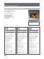
Standards, certification and technical characteristics
PRESENTATION OF THE PRODUCT
Stûv S.A.
B-5170 Bois-de-Villers (Belgium)
15 QA 151322916
EN 13229 : 2001 / A2 : 2004
Wood insert Stûv 22/90 SF
Minimum insulation thickness with
regard to potentially combustible
materials (conductibility of the
insulating material used
at 400°C = 0.14 W/mK) :
– behind : 7cm
– on the sides : 7cm
– below : 5cm
– above : 6cm
Recommended fuel : wood logs only
CO emissions : 0.08%
Average smoke temperature
at rated power : 284°C
Nominal heat power : 15kW
Efficiency : 80%
Particle emissions : 12mg/Nm3
Please read the installation
instructions and directions for use !
Stûv S.A.
B-5170 Bois-de-Villers (Belgium)
16 QA 161322917
EN 13229 : 2001 / A2 : 2004
Wood insert Stûv 22/70 SF
Minimum insulation thickness with
regard to potentially combustible
materials (conductibility of the
insulating material used
at 400°C = 0.14 W/mK) :
– behind : 9cm
– on the sides : 7cm
– below : 0cm
– above : 8cm
Recommended fuel : wood logs only
CO emissions : 0.08%
Average smoke temperature
at rated power : 262°C
Nominal heat power : 11kW
Efficiency : 80%
Particle emissions : 20 mg/Nm3
Please read the installation
instructions and directions for use !
Stûv S.A.
B-5170 Bois-de-Villers (Belgium)
15 QA 151322915
EN 13229 : 2001 / A2 : 2004
Wood insert Stûv 22/110 SF
Minimum insulation thickness with
regard to potentially combustible
materials (conductibility of the
insulating material used
at 400°C = 0.14 W/mK) :
– behind : 11cm
– on the sides : 14cm
– below : 5cm
– above : 13cm
Recommended fuel : wood logs only
CO emissions : 0.09%
Average smoke temperature
at rated power : 283°C
Nominal heat power : 16,5kW
Efficiency : 80%
Particle emissions : 26 mg/Nm3
Please read the installation
instructions and directions for use !
The Stûv 22 is covered by patent
No. EP1445541
Stûv 22 intermittent stoves comply
with European EN standards (output,
gas emissions, safety etc).
Data provided in this notice are
supplied by a certified laboratory.
Test results according to
EN 13229 : 2001 and
13229–A2 : 2004 standards
(built-in stoves)

5
Stûv 22 - installation [en] - 04/2016
Standards, certification and technical characteristics (continuation)
Other technical characteristics
22/70 SF 22/90 SF 22/110 SF
Minimum draught needed to obtain the
rated calorific output 12 Pa 12 Pa 12 Pa
Weight-flow ratio of smokes 10,7 g/s 12.5 g/s 14.9 g/s
Flue spigot 309°C 326°C 337°C
Minimum diameter of the duct for the
intake of outside combustion air 200 cm2200 cm2200 cm2
Optimum output range for usage 4 - 12 kW 5-16 kW 5 -18 kW
Range of wood consumption per hour
recommended at 12% humidity 1,2 - 3,8 kg 1.6-5 kg 1.6-5.6 kg
Maximum limit for consumption
of wood per hour to avoid overheating
the system
3,8 kg/h 5 kg/h 5.6 kg/h
Maximum length of logs
in vertical position - cm - cm - cm
Maximum length of logs
in horizontal position 33 cm 50 cm 80 cm
System mass 230 kg 250 kg 250 kg
Recommandations
We strongly recommend you entrust
the installation of this Stûv to a
qualified professional who is able to
ensure that the characteristics of the
smoke flue correspond to the stove
installed.
The installation of the stove, its
accessories and the materials which
surround it must comply with all
regulations (local and national) and all
standards (national and European) for
the country of installation.
Some national and local regulations
require the installation of an access
flap in the connection between the
stove and the smoke flue.
The stove has to be installed in such
a way as to facilitate access to sweep
the stove, the connection duct and
the smoke flue.
Any modification made to the system
may be dangerous and will invalidate
the guarantee.

6
1
4
5
6
7
8
9
2
3
10
Stûv 22 - installation [en] - 04/2016
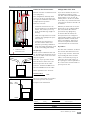
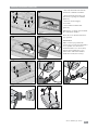
Overview
Supplied as standard with the stove
[1] Stove
[2] Combustion chamber trim
(choose from light or dark)
Finish
[3] Door frame (Provided
with the chosen cladding)
[Thanks to its range of configurations, Stûv
offers a choice of claddings and finishes.
Please refer to the appropriate manuals for
installation instructions.]
Option
[4] Barbecue kit
[5] Fan kit
[6] Fan unit
[7] Nozzle Ø100mm for external air inlet
(provided with flexible tube)
[8] Nozzle Ø160mm for external air inlet
+ make-up air (provided with flexible
tube)
[9] Nozzle and bend Ø160mm for
external air inlet + make-up air
[10] Front insulation kit

7
Stûv 22 - installation [en] - 04/2016
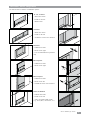
The various Stûv 22 configurations
The Stûv 22 offers a number of installation options:
L4 frames
- 92mm door frame
- handle on the left
– available in version to be trimmed
A4 frames
- 125mm door frame
- handle on the right
– to be used with slim-line partitions
only
DS front panel
- 125mm door frame
- handle on the right
DH front panel
- 125mm door frame
- handle on the left
– available in version to be trimmed
Unit to be trimmed
- 125mm door frame
- handle on the left
– unit to be trimmed with panels
(e.g.: wood, fibre, metal sheet, etc.)
S1 - S4 - H frames
- 92mm door frame
- handle on the left
- Welded sides

8
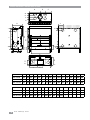
A B C D E F G H I J K L M N O P
Stûv 22/70 355 260 94 103 110 81 212 505 117 1014 111 610 640 220 600 470
Stûv 22/90 455 250 205 103 110 81 212 505 135 900 137 540 570 220 600 670
Stûv 22/110 555 250 305 103 110 81 212 505 135 800 137 440 470 220 600 870
Q R S T U V W X Y Z AA AB
Stûv 22/70 186 95 220 265 30 15 420 160 135 105 111 1412
Stûv 22/90 186 95 320 265 30 15 420 160 235 120 132 1272
Stûv 22/110 186 95 420 265 30 15 420 160 235 120 132 /
Dimensions de l'appareil sans porte et sans finition
C
B
P
A
Y
Z
D
G
L
I
H
S
W
X
V
T
J
K
AA
AB
M
min N
Max O
RQE
F
U
Stûv 22 - installation [en] - 04/2016
Device dimensions without door or finish

9
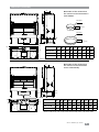
A B C* D E F G H I
Stûv 22/70 520 355 198 15 130 30 180 220 600
Stûv 22/90 520 455 198 15 130 30 180 220 600
Stûv 22/110 520 555 198 15 130 30 180 220 600
A B C* D E F G H I J
Stûv 22/70 520 355 198 15 200 130 30 180 400 600
Stûv 22/90 520 455 198 15 200 130 30 180 400 600
Stûv 22/110 520 555 198 15 200 130 30 180 400 600
Ø100mm
25 mm
10 mm
Ø160mm
A
B
C
D
E
F
G
H
A
B
C
D
E
GFmin H
Max I
min I
Max J
Stûv 22 - installation [en] - 04/2016
Dimensions (continued)
Dimensions of the air box when
the external air inlet connection is
at the bottom.
* distance between the centre of the air inlet nozzle and the centre of the smoke outlet.
* distance between the centre of the air inlet nozzle and the centre of the smoke outlet.
Dimensions of the air box when
the external air inlet connection
comes in horizontally.

10
1
2
3
4
Stûv 22 - installation [en] - 04/2016
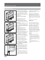
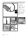
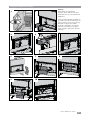
Combustion air inlet
PREPARATION OF THE AREA
The stove needs air for combustion,
especially when it is working in open
fire mode. The Stûv 22 is designed to
be connected directly to an outside
air inlet (independent from the air
inside the house). We recommend this
configuration.
Drawing of air from outside
- upright under the stove, just
underneath the air box to be
connected via a nozzle and a
Ø160mm flexible tube (combustion
air + make-up air for open fire mode)
[diagram 1].
- horizontally, behind the stove, to be
connected with the Ø160mm flexible
tube with pivoting bend (combustion
air + make-up air for open fire mode)
[diagram 2].
- upright under the stove, just
underneath the air box to be
connected via a nozzle and a
Ø100mm flexible tube (combustion
air only, make sure there is an
additional external air inlet valve in the
room for open fire mode) [diagram
3]. Warning: this configuration is
n o t r e g u l a t e d i n F r a n c e a n d I t a l y .
- under the stove, at the front, if the
air box is not connected. [diagram 4]
(warning, if the stove has a fan
and the combustion air box is
not connected, you will need to
incorporate a fan box so that it does
not use up the combustion air).
The duct that brings in outside
air... (whether it is connected to
the stove or not)
... will be protected on the outside
by a grill the free passage section of
which is at least equivalent to the
section of the air inlet. Please note
that the infiltration of water and the
effect of the wind can damage the
system.
... will ideally be fitted with a closure
valve (for example, the Stûv valve –
see below) to prevent the room from
becoming cold when the stove is not
in use.
... will be as short as possible to
prevent pressure loss and to prevent
making the house cold.
If you use our standard flexible Ø
160 mm flue, we recommend a
maximum length of 6 m and no more
than 6 elbows. If you exceed these
guidelines, you must compensate with
a greater diameter and/or a smoother
duct.
Careful not to crush the flue.
Make-up air.
The cross-section of 160 mm as
well as the installation of a Stûv air
box enables a so-called “make-up”
air circuit to be created. This air,
distributed at the bottom of the
glass, feeds combustion when the
user changes to “open fire” mode.
It is therefore possible to use the
Stûv 22 in “open fire” mode without
consuming air from the room! This
configuration is highly recommended
for installations in very isolated
residences.
Warning!
– The air box cannot under any
circumstances bear the weight of
the device! Check that the device
is resting on its feet, that these are
well fastened and that the device is
slightly higher than the base of the
air box.
– The bottom air box is not
compatible with forced convection
(fan).

11
5
6
7
Stûv 22 - installation [en] - 04/2016
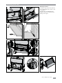
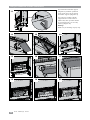
Combustion air inlet
A tube cover is provided with the
stove. Some claddings need this to be
installed so that the tube is not visible
via the gap between the floor and the
bottom of the cladding [diagram 7].
If it is not possible to bring in
outside air near the stove
(most unfavourable case)...
... ensure there is sufficient
replenishment of air in the room when
the stove is in use.
Please note
1) Be careful with air extraction
systems (kitchen hoods, air
conditioning, mechanically-controlled
ventilation, other stoves) in operation
in the same space or in an adjacent
room. They also use lots of air and
can cause a depression in the room
and prevent the stove from operating
correctly (risk of draughtback). They
can affect the operation of the stove
even if it is connected to an outside
air inlet.
2) If a forced convection system
is installed, you are strongly
recommended to draw in air from the
outside or from the room (in all cases,
away from the mantelpiece) [diagram
6].
Ensure the configuration chosen fully
meets local and national regulations.

12
1
2
3
Stûv 22 - installation [en] - 04/2016
Smoke flue
Ensure the flue’s dimensions, the gaps
from combustible materials and glass
etc. meet local regulations and the
applicable installation standards in line
with good practice.
Basic information
For good draught, the stove must be
suited to the flue (or vice versa).
An oversized flue is as detrimental to
the smooth operation of the stove as
an undersized flue.
The flue should be as straight
as possible and insulated to
encourage the draught and prevent
condensation.
The ideal solution is a flue built inside
the building and thermally insulated.
Take care to avoid heat loss !
If several flues are available : only use
one of them. Block up the unused
flues at the top and bottom and,
generally speaking, ensure that the
top of the recess where the stove is
fitted is air-tight [diagram 1].
IMPORTANT!
Beware of any heat loss
Unused flues or ventilated spaces
between walls can generate
undesirable counter-draughts (the
hot air escapes) [diagram 2], or cause
the entry of cold air from outside
[diagram 3].
Diameter of the
smoke outlet:
22/70 : D180 mm
22/90 : D200 mm
22/110 : D200 mm
Some flue configurations may
require a different diameter than that
provided as standard.
Warning!
If there is a false ceiling in your recess,
this false ceiling must be sealed.
The entire area covered (floor, wall
and ceiling of the recess) by the stove
must be made of noncombustible
materials.
An outside flue without any insulation
must be avoided.
The stove can only be connected to a
smoke flue serving several systems on
4 conditions :
- The stove is equipped with the
“automatically closing door” option.
– all the systems connected to this
flue use the same fuel,
– they have automatically closing
doors,
– the flue has been checked for
this type of usage; consult a
professional if necessary.
Caution !
The appliance must not be operated in a
smoke control area in the Open fire mode

13
a b
60 mm
15 mm ( 2mm)
35 mm ( 0,8mm)
X mm
1
2
Stûv 22 - installation [en] - 04/2016
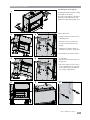
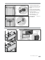
Connection to the smoke flue
Allow play of 2 mm/m for expansion
of the flue.
Calculation for the height of the
connection duct
The following must be added to the
height which separates the Stûv from
the ceiling connection:
- approximately 60 mm for the part of
the flue recessed into the ceiling.
- for the recessing of the flue at the
stove, add 15 mm for a flue that is 2
mm thick and 35 mm for a stainless
steel flue that is 0.8 mm thick.
Air-tightness
The various components which make
up the connection between the stove
and the smoke flue and those which
make up the flue itself have to be
fitted so that they are airtight for the
condensation [diagram 2/a] rather
than the smoke [diagram 2/b].
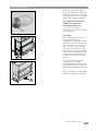
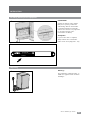
Holding capacity of the structure
Ensure that the resistance of the
floor is sufficiently strong to support
the stove and the construction of
the cladding. If in any doubt, please
consult a specialist.

14
r = 80 cm
Stûv 22
12
Stûv 22 - installation [en] - 04/2016
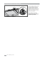
The stove's surroundings and decoration
The recess
The Stûv 22 is systematically fitted with
a finishing accessory (frame or front
panel).
The dimensions of the recess will depend
on the finish chosen.
The stove must be able to expand freely.
The brickwork or decorative materials
must not enter into contact with the
stove under any circumstances; leave a
gap of at least 5 mm.
This recess and/or the space around
the stove must be ventilated to prevent
"heat traps". Any closed or contained
space constitutes a heat trap which
causes the walls to heat up. Circulation
of air can be ensured by having an air
inlet in the base of the cladding (hood or
recess) and an outlet in the upper part
[diagram 1].
If necessary, insert insulating material
of the thickness required between the
stove and inflammable materials [see
pages 3].
Leave sufficient space around the fan (if
you have chosen this option).
Radiated heat
Significant heat may be radiated through
the glass door. Ensure the materials
exposed to this radiated heat are
resistant to high temperatures [diagram
2].
Radiated heat zone
Safety
Depending on the type of floor in front
of the device, it may be necessary to
provide for a protective plate (e.g. a
hearth plate is recommended to protect
a wooden floor).
The use of flammable materials to finish
a Stûv22 is only guaranteed by Stûv
with Stûv finishes and in accordance
with the requirements for each finish.
S1 frame dimensions

15
min. 2%
100%
100% - 133%
min Max
1
2
3
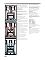
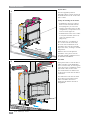
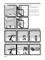
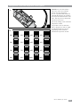
Stûv 22 - installation [en] - 04/2016
Circulation of convection air
Configuration of the ducts
If you do not install a fan, ducts are
not mandatory. However, please
note that a fibrous insulating material
inserted in the recess can give off
volatile particles. In this case, thanks
to the ducts, any contact between the
convection air and these materials can
be avoided.
Whether you install a fan or not, the
ducts must rise in a gradual gradient
(min 2%) towards the outlet to
prevent heat traps [diagram 2].
To ensure balanced air flow, the
duct system has to be configured
symmetrically (number of ducts, their
height, the number of bends, their
degree of insulation). This factor is
even more important with natural
convection than forced convection.
In practice...
The ducts have a diameter of 150 cm.
The air inlets and outlets have to be
set up so they cannot be obstructed.
If you install grills on the air inlets/
outlets, ensure that the passage of
useful air in these grills (surface of
the openings) is at least equivalent to
the section of the air inlets/outlets to
prevent pressure loss.
Air passage
Hot air is more voluminous than cool
air. To facilitate the abstraction of hot
air, more air outlets to the stove than
inlets are required.
Therefore, if you open two air inlet
holes in the base of the stove, you
have to open three in the outlet.
In France : minimum of 400 cm² for
the inlet and 500 cm² for the outlet.
air inlet
section
air outlet
section
air inlet section
air outlet section
number of vents to open
on the fireplace
320 cm2320 cm21 ≥ 2/3 OK 2 inlets / 2 outlets
320 cm2640 cm21/2 < 2/3
320 cm2500 cm22/3 ≥ 2/3 OK 2 inlets / 4 outlets
Natural or forced convection ?
Natural convection is sufficient in most
cases [diagram 1].
This configuration obviously allows
easier (no electrical connection) and
less expensive installation and ensures
completely silent operation.
However, a fan unit :
– enables the amount of air to be
increased and for it to be distributed
further : this is vital if you set up
an air circuit with longs lengths of
ducting,
– allows the temperature to be made
constant more quickly in the space
to be heated,
– enables the air temperature to
be reduced in the outlet vents
(therefore preventing combustion
of the ash and the depositing of ash
on the surrounding plasterwork),
≥ 2/3
Other regulations to be observed :
air inlet section
air outlet section
These air sections must correspond to
the vents opened on the system.
Examples in the table below.
combustion zone
convection zone

16
MAX 10 m
MAX 3 m
1
2
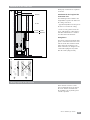
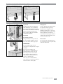
Stûv 22 - installation [en] - 04/2016
Forced convection
Please note !
The fans supplied by Stûv are
designed to direct room air and not to
be installed in the hot air circuit at the
stove's outlet.
2 ways of creating an air circuit :
– install ducts in the stove's inlet to
draw in room air distant from the
stove [diagram 1] or even from
another room in the house. For this
configuration, it is imperative to use
a fan in a water-tight case
– install the ducts in the stove's outlet
to carry hot air further (max. 3 m)
even to an adjacent room
[diagram 2].
In tthe both cases, a circulation of
air is created : The air reheated by
the stove moves towards the areas
from where the room air was drawn
(depression zone), ensuring a constant
temperature.
Whatever the air circuit planned
around the stove, please note the
local and national regulations in force
for this kind of installation.
Air return
If you plan to have a room air inlet or
outlet in another room (distribution
across several rooms), do not forget to
create air passages of sufficient section
(at least the same) for the return :
The air which has been drawn from
or directed to a room must be able to
return there.
The abstraction of air must be offset
by a return to prevent depressions
in the room where the stove is
situated as this involves the risk of
draughtback.

17
Stûv 22 - installation [en] - 04/2016
Forced convection (continuation)
The advantages and disadvantages of these 2 types of installation
Outlet ducts Inlet ducts
– depression near the stove that risks
affecting the drawing of air
+ excess pressure close to the system
(encourages the drawing of air)
– geometry of the layout restricted :
the ducts must always rise in a slight
gradient without any obstructions in
the route to prevent the hot air from
stagnating.
+ bends can be used in the ducts,
reverse gradient,... (no air stagnation)
– significant drop in the air temperature
along its route (maximum 3 m).
+ no variation in room air temperature
on its route which means it can
be obtained from further away
with better direction and greater
temperature consistency in the room.
+ easier to implement if not planned for
in the architecture or in the case of
renovation
– difficult to implement if not planned in
the architecture.
In practice...
In forced convection, the use of ducts
is compulsory so that the air exits the
stove and does not immediately enter
into the fan (which would disrupt the
air circuit within the cladding).
Setting up the power supply
(2 conductors + ground) and the fan
controls ; the connection has to be
protected by a bipolar fuse.
Please also see the notes in the
previous section.
Please note
To prevent the fan from affecting
combustion, do not put the
combustion air inlet and the
convection air inlet too close to one
another.
The advantages of using a fan
box.
Installing an air unit makes it possible
to channel the air.
The advantages of this are as follows:
1. It avoids agitating the dust in the
recess.
2. It avoids creating negative pressure
in the recess.

18 Stûv 22 - installation [en] - 04/2016
Insulating the fireplace : pros & cons
Safety
Take the necessary precautions to
prevent excessive heating of the
recess walls and construction materials
close to the stove (e.g. wooden
beams) and insulate these materials
according to industry regulations and
the applicable standards depending on
their flammability.
Improvement of performance
Thermal insulating materials can also
be placed against the stove to improve
its performance.
The advantage : reduction of heat
loss : this applies in particular if the
stove is against an external wall ; if this
is not the case, heat will not be lost :
it will dissipate into the brickwork and
then into adjacent rooms .
The disadvantages: when using
a fibre insulator (mineral wool), a
sealed recess has to be built and ducts
installed for the convection circuit
to prevent insulation particles being
suspended in the convection air or in
the room where the stove is installed.

19
2
Stûv S.A. B-5170 Bois-de-Villers www.stuv.com
160595
22110 SF
1
1
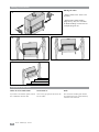
Stûv 22 - installation [en] - 04/2016
On taking delivery of the equipment
INSTALLATION
Unpacking
Complaints
If you need to make a complaint,
always indicate the serial number
visible on the stove [diagrams 1 & 2].
IMPORTANT!
Signing the delivery forms signifies
that you accept the product and
acknowledge that the merchandise
is compliant with the merchandise
ordered. It is therefore very important
to check the integrity of the
merchandise on delivery.
Warning !
The paintwork is relatively fragile, so
handle the appliance with care when
installing it.

20
1 2
a
b
c
d
ef
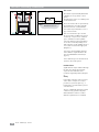
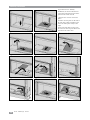
Stûv 22 - installation [en] - 04/2016
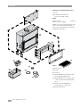
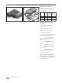
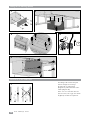
Checking the contents
back
fireproof
bricks
side
fireproof
bricks
deflector
vermiculite
bricks
22/70 6 8 1
22/90 6 8 2
22/110 4 6 3
On the device, you will find:
– Fireproof and vermiculite bricks
which line the combustion chamber
You will find a box in the stove,
containing:
– The bracket for the sloping
vermiculite bricks [diagram 2a and
2b]
– Sloping deflectors [diagram 2c]
– The instructions [diagram 2d]
– The cold grip [diagram 2e]
– The assembly template [diagram 2f]
– bag of accessories containing:
- Screw and nut to adjust
the air inlet (refer to the chapter on
setting the air inlet)
- two bolt fittings (refer to
the chapter on positioning the door
frame)
- fastening screws for the
legs
- fastening screws for the
smoke outlet
- fastening screws and
washers for the air box fittings.
– a pair of white gloves.
If accessories have been ordered
(frame, ventilator…) they are placed
around the fireplace or its packaging.
Please ensure due reception of all
accessories ordered.
Page is loading ...
Page is loading ...
Page is loading ...
Page is loading ...
Page is loading ...
Page is loading ...
Page is loading ...
Page is loading ...
Page is loading ...
Page is loading ...
Page is loading ...
Page is loading ...
Page is loading ...
Page is loading ...
Page is loading ...
Page is loading ...
Page is loading ...
Page is loading ...
Page is loading ...
Page is loading ...
-
 1
1
-
 2
2
-
 3
3
-
 4
4
-
 5
5
-
 6
6
-
 7
7
-
 8
8
-
 9
9
-
 10
10
-
 11
11
-
 12
12
-
 13
13
-
 14
14
-
 15
15
-
 16
16
-
 17
17
-
 18
18
-
 19
19
-
 20
20
-
 21
21
-
 22
22
-
 23
23
-
 24
24
-
 25
25
-
 26
26
-
 27
27
-
 28
28
-
 29
29
-
 30
30
-
 31
31
-
 32
32
-
 33
33
-
 34
34
-
 35
35
-
 36
36
-
 37
37
-
 38
38
-
 39
39
-
 40
40


STUV 22-110-DF Installation guide
- Category
- Stoves
- Type
- Installation guide
- This manual is also suitable for
Ask a question and I''ll find the answer in the document
Finding information in a document is now easier with AI
Related papers
-
STUV 22-110 Installation guide
-
-
-
-
-
-
-
-
-
Other documents
-
Whirlpool HD R00 B Owner's manual
-
Sharkoon M25-W Owner's manual
-
Giacomini K272 Operating instructions
-
-
Philips MCW770/22 Quick Installation Guide
-
-
-
Genius PANDORA PRO Owner's manual
-
-
 Wood Cuatro-7 compact 70 Installation guide
