Page is loading ...

CL-B101D40-TCRTD Manual (d0099) Page 1
CL-B101D40-TCRTD
Smart 101 segment 4 digit LED Tricolor or Mono-color
digital bargraph controller with four fully programmable
set points for J, K, R, and T type thermocouples and
RTD inputs in a switchboard style case.
0.56” LEDs
•
External transmitters or signal conditioners can be eliminated by
direct connection of the sensor output to Plug-in Input Signal
Conditioners- available are thermocouples (J, K, R and T types)
or RTD (Pt-100. 385 and 392 curves. 3 wire/4wire). Digitally
Linearized.
•
Optional isolated 16 bit analog output. User or factory scalable to 4
to 20 mA, 0 to 20 mA or 0 to 10 V across any desired digital span
from ± one count to the full scale range of – 1999 to 9999 (12000
counts).
•
A Programmable Tricolor (Red-Green-Orange) or mono color (red or
green), 101 segment high brightness bargraph.
•
Red 4-digit LED display with a range of -1999 to 9999
(12000 counts). Optional green digital display.
•
Front panel LED annunciators provide indication of setpoint status.
•
Two 9 Amp Form C, and two 4 Amp Form A or 4 x 4 Amp Form A
relays available
.
•
Auto-sensing AC/DC power supply. For voltages between
85-265 V AC / 95-300 V DC (PS1) or 18-48 V AC / 10-72 V DC
(PS2).
•
Provision to connect an external programming lockout switch.
•
Provision for external DIM switch to reduce the brightest
display setting by 50%.
•
Automatic intelligent averaging, smooths noisy signals while
providing a fast display response to real level changes.
General Features
Specifications
• Thebargraphcandisplay,full
scale, any desired portion of
the digital reading.
• Setpoint1hasdelay-on-make
and delay-on-break plus
a special “pump on pump
off” mode that creates a
Hysteresis Band between SP1
and SP2.
Software Features
•
Four programmable setpoints
with adjustable Hysteresis.
•
Bargraph center zero function.
• Relayactivationcanbeselect-
ed to occur above (hi) or below
(Lo) each setpoint.
• Digitaldisplayblanking.
• Decimalpointsetting.
• Four-levelbrightnesscontrol
LEOPARD
FAMILY
Input Specs: ������������������ Depends on Input signal conditioner
A/D Converter: �������������� 14 bit single slope
Accuracy: ���������������������� ±(0�05% of reading + 2 counts)
Temp. Coeff�: ����������������� 100 ppm/°C (Typical)
Warm up time: ��������������� 2 minutes
Conversion Rate: ���������� 10 conversions per second (Typical)
Digital Display: ��������������
4 digit 0.56" LED red (std), green (optn)
Range
–1999 to 9999 counts�
Bargraph Display: ���������
101 segment 235º circular red (standard),
Green (optional) or tricolor (optional) LED�
Polarity: ������������������������� Assumed positive� Displays – negative
Decimal Selection: �������� Front panel button selectable, X•X•X•X•
Positive Overrange: ������ Bargraph and top segments of digital display
flash�
Negative Overrange: ���� First segment of bargraph and bottom seg-
ments of digital display flash�
Relay Output: ���������������� Two 9 Amp Form C relays, two 4 Amp Form
A relays or
4 x 4 Amp Form A relays
Analog Output: ������������� Isolated 16 bit user scalable mA or V
OIC (mA out) ��������������
4-20 mA @ 0 to 500Ω max loop resistance
OIV (volts out) �������������� 0-10 V DC @ 500 ٠or higher resistance
Power Supply: ��������������� AC/DC Auto sensing wide range supply
PS1 (std) ��������������������
85-265 VAC / 95-300 VDC, 50-400Hz 4.2W
PS2 �����������������������������
18-48 VAC / 10-72 VDC, 50-400Hz 4�2W
Operating Temp�: ���������� 0 to 60°C
Storage Temp: ��������������� –20°C to 70°C
Relative Humidity: �������� 95% (non condensing)
Case Dimensions: ��������
Bezel (4.48"x4.48") 113.8x113.8mm
Depth behind bezel (4.23") 107.46 mm
Plus (0�48”) 12�24 mm for connectors
Weight: ���������������������������16 oz�, 1lb 4 oz when packed
Table of Contents
Bargraph Center Point Display Mode Selection ... 6
Bargraph Color Programming Mode ........ 9
Case Dimensions ...................... 11
Component Layout..................... 11
Connector Pinouts ...................10-11
Controls and Indicators .................. 2
Decimal Point and Brightness Selection ..... 5
Programming Conventions................ 2
Setpoint Setting & Relay Conf. Mode ......8-9
Software Features ...................... 1
Software Logic Tree ..................... 3
Specifications.......................... 1
Two Point Analog Range Setting & Calibration .... 7
Thermocouple and RTD Type Selection Mode......4
Digital Span Selection for Bargraph Display .. 5
Digital Span Selection for Analog Range Output... 6
Functional Diagram .................... 10
General Features ....................... 1
Input Module Calibration Procedures ...... 12
Ordering Information ................... 13
Pin Descriptions ....................... 10

Page 2 CL-B101D40-TCRTD Manual (d0099)
Front Panel Buttons
Program Button
The
P
button is used to move from one program step to the next.
When pressed at the same time as the button, it initiates the
calibration mode. When pressed at the same time as the but-
ton, it initiates the setpoint setting mode.
101 Segment
Bargraph
Up Button
When in the operational display, pressing the button allows you
to view the setting of the saved Peak and Valley Values.
When setting a displayed parameter during programming, the
button is used to increase the value of the displayed parameter.
Down Button
When in the operational display, pressing the button allows you
to change the Brightness Level as well as to view the setting of
the setpoints SP1, SP2, SP3 & SP4.
When setting a displayed parameter during programming, the
button is used to decrease the value of the displayed parameter.
Front Panel LED Display
Annunciator LEDs
The annunciator LEDs indicate the alarm status. They are labeled
from bottom to top: SP1, SP2, SP3, SP4.
Digital LED Displays
The digital LED displays are used to display the meter input
signal readings. They also display the programming settings
during programming.
Setpoint Indication
The position of setpoints on the bargraph display are indicated by
an ON or OFF segment dependent on the bargraph display being
above or below the setpoint.
Setpoints
indicated
by an ON
Segment
Setpoints indicated
by an OFF Segment
Controls and Indicators
This symbol represents the
OPERATIONAL DISPLAY.
This is the PROGRAM button.
This is the UP button.
This is the DOWN button.
When a button is shown, press and
release it to go onto the next step in the
direction indicated by the arrow. When
an alternative dotted line is shown, this
indicates that an alternative logic branch
will be followed when a particular option
is present.
When two buttons are shown side by side
and enclosed by a dotted line, they must
be pressed at the same time then released
to go onto the next programming step.
If an X appears through a digit, it means that
any number displayed in that digit is not rel-
evant to the function being explained.
P
[Span]
[10000]
P
P
When the
and
buttons are shown
together, the display value can be increased
by pressing and releasing the
button
or decreased by pressing and releasing the
button.
When the
and
buttons are shown
with two displays, either display can be
selected by pressing and releasing the
or
buttons.
When two displays are shown together
with bursts, this indicates that the display is
toggling (flashing) between the name of the
function and the value.
Text or numbers shown between square
brackets in a procedure indicate the pro-
gramming code name of the function or the
value displayed on the meter display.
When there are more than two display selec-
tions they are shown in brackets below the
first display and are also selectable by
pressing and releasing the
or
buttons.
A dotted line enclosing an entire logic dia-
gram indicates that programming branch
will appear only when a particular option is
present.
To explain software programming procedures, logic diagrams are
used to visually assist in following the programming steps. The
following symbols are used throughout the logic diagrams to
represent the buttons and indicators on the meter:
Programming Conventions
[X•XXX]
[XX•XX]
[XXX•X]
[XXXX•]
[XXXX]
Front Panel Controls and Indicators
LED
Annunciators
for Setpoints
1-4
Single or
Tri-color
Bargraaph
Display
UP
Button
DOWN
Button
PROGRAM
Button
7 Segments
Digital
Display

CL-B101D40-TCRTD Manual (d0099) Page 3
Software Logic Tree
The CL-B101D40-TCRTD is an intelligent bargraph meter with a
hierarchical software structure designed for easy programming
and operation, as shown below in the software logic tree.
Software Version is Displayed on Power-up
When power is applied, all segments of the bargraph and
digital display light up for 3 seconds. The version number of
the installed software is then displayed for 2 seconds, after
which, the operational display indicates the input signal.
15 Second Program Timeout
Except for ZERO and SPAN settings in the Analog Output Range Setting and
Calibration Mode (cLo and chi), the meter has a 15 second program timeout. If
no buttons are pressed for 15 seconds in any of the other programming
sequences, the meter will exit the programming mode and return to the opera-
tional display. Any program changes that were made prior to pressing the
P
button in the preceding step will not be saved.
[orAn]
[rEd]
[H]
[L]
NOTE: Will only
appear if a tricolor
display is installed
[orAn]
[rEd]
[orAn]
[rEd]
[orAn]
[rEd]
[orAn]
[rEd]
BARGRAPH COLOR
PROGRAMMING MODE
See Page 9
Tricolor Bargraph
The tri-color bargraph is designed
like a traffic light, to display either
red, orange or green, but only one
color at a time. The color to be
displayed is selected in two ways.
The first step is to select the color to
be displayed when the bar is “below”
whichever set point is set to the
lowest position.
The second step is to select the color
to be displayed when the bar is
above each specific setpoint,
regardless of the order or position to
which the set points are set.
However, if two or more setpoints
with differently specified colors are
positioned at the same set point
value, the color specified for the set
point with the highest identifying
number will be displayed. When
setpoints are set to the same value,
the SP4 color overrides the SP3
color, the SP3 color overrides the
SP2 color, and the SP2 color
overrides the SP1 color.
Set Setpoint 1
(SP1)
Delay-on-Make
(doM)
Delay-on-Break
(dob)
0 to 9999 seconds
Relays
Activation
[rLYS] (H) High
the relay
energizes when
the setpoint is
exceeded
[rLYS] (L) Low
the relay
energizes below
the setpoint.
Setpoint 2 (SP2)
NOTE: [dom] [dob]
Functions are only
available for SP1
0 to 9999 seconds
Pump (PUM)
Hysteresis (hYSt)
Hysteresis (hYSt)
Hysteresis (hYSt)
Setpoint 3 (SP3)
Setpoint 4 (SP4)
Operational Display
MAIN MENU
BRIGHTNESS AND
SETPOINT VIEW MODE
Bargraph Center Point
Display Selection (cto)
This branch will
only appear if
the analog
output option
is installed
Back to
Operational
Display
Digital Display ON/OFF
Selection (diSP)
Sub-menu MODE
Calibration Mode
Calibration
Input
Calibration
Output
Calibrate Analog
Output Lo
Calibrate Analog
Output Hi
Select the Digital
Reading at which
the Analog Output
Hi (chi) will occur
Select the Digital
Reading at which
the Analog Output
Lo (cLo) will occur
This branch will only appear
if the analog output option
is installed
DIGITAL SPAN SELECTION
FOR ANALOG RANGE OUTPUT
See Page 6
DIGITAL DISPLAY ON/OFF
See Page 6
BARGRAPH CENTER POINT
DISPLAY MODE SELECTION
See Page 6
TWO POINT ANALOG OUTPUT
RANGE SETTING AND CALIBRATION
See Page 7
Bargraph Display
Scale Lo Range
Setting (bLo)
Bargraph Display
Scale hi Range
Setting (bhi)
Display
Brightness (br)
1 Dimmest
2 Dim
3 Bright
4 Brightest
BRIGHTNESS SELECTION
See Page 5
DIGITAL SPAN SELECTION
FOR BARGRAPH DISPLAY
See Page 5
if Analog Output is not installed,
goes directly to Input selection
+
–
4.00
+
–
20.00
1 Dimmest
2 Dim
3 Bright
4 Brightest
SETPOINT SETTING AND
RELAY CONFIGURATION MODE
See Page 8
H or L
H or L
H or L
H or L
SP1
[H]
[L]
SP2
[H]
[L]
SP3
[H]
[L]
SP4
[K]
[r]
[t]
If RTD module is installed
this menu will appear.
3 or 4 wire
RTD input
selection
RTD select type
P385 or P392
If Thermocouple module is
installed this menu will appear.
Resolution select
Thermocouple
select
Select J, K, R or T
1°
0.1°
Degree select
°C
°F
THERMOCOUPLE OR RTD TYPE,
RESOLUTION AND DEGREE
C OR °F SELECT
See Page 4
Pump On Pump Off
When PUM is selected ON,
and SP2 is set at a value
higher than SP1, the SP1
relay will operate in
a special "pump on pump off"
Hysteresis mode. SP2 acts
as the upper limit and SP1
acts as the lower limit of the
Hysteresis Band.
For filling applications, rLYS
should be set to LhLh. SP1 will
then activate for inputs less than
the SP1 setpoint, and remain
ON until the SP2 setpoint is
reached.
For emptying applications,
rLYS should be set to hhhh.
SP1 will then activate for inputs
greater than the SP2 setpoint,
and remain ON until the SP1
setpoint is reached.
Peak
[PEAK]
Reset
PEAK
Reset
VA LY
Valley
[VALY]
PEAK & VALLEY
VIEW & RESET
FL-B101D40H_LogicTree_v2.0
° C
° F
Displays °C or °F whichever
is the opposite of the
selected operational display

Page 4 CL-B101D40-TCRTD Manual (d0099)
STEP A Enter the Calibration Mode
1)
Press the
P
and buttons at the same time.
Display toggles between [CAL] and [oFF].
2) Press the or button. Display changes from [oFF]
to [on].
3) Press the
P
button.
STEP B If the Display toggles between [CAL] and [out] the
optional Analog Output hardware is installed. In which
case select [CAL] [out]. Display toggles between [thEr]
or [rtd] depending on whether a IT10 Thermocouple
Input Module or a IT11 RTD Input Module are detect-
ed by the soft ware. If no optional output hardware is
installed the menu will skip directly to STEP C.
STEP C Sensor Type Selection
1) Using the and buttons, adjust the display
to the desired sensor type.
2) Press the
P
button. Display toggles between
[rES] resolution select and previous [rES] setting.
STEP D Set the Resolution
1) Using the and buttons, adjust the display
to the desired resolution [rES] value.
2)
Press the
P
button.
Display toggles between
[dEG] and previous [dEG] selection.
STEP E Selection of Degree C or Degree F
1) Using the and buttons, adjust the display to
either ˚C or ˚F.
2) Press the
P
button.
Calibration Procedure
MAIN MENU
Operational Display
Sub-menu
MODE
STEP A Calibration
Mode
STEP B Calibration
Mode
To Digital Span Selection for
Bargraph Display Page 5
cAL out/iP branch will only appear if
the analog output option is installed,
otherwise cAL on goes directly to step c.
To Digital Span Selection
for Bargraph Display
See Page 6
To Two Point Analog
Output Range Setting
and Calibration
See Page 7
[K]
[r]
[t]
If RTD module is installed
this menu appears
3 or 4 wire
RTD input
selection
RTD select type
P385 or P392
If Thermocouple module is installed
this menu appears
Resolution select
Thermocouple select
Select J, K, R or T
STEP C
STEP D
STEP E
1°
0.1°
Degree select
°C
°F
THERMOCOUPLE OR RTD TYPE,
RESOLUTION AND DEGREE C OR F SELECT
Input Sensor Reso-
lution °C Range °F Range
J T/C
K T/C
R T/C
T T/C
100Ω RTD (385 curve)
100Ω RTD (392 curve)
-120 to 760°C
-120.0 to 530.0°C
-120 to 1370°C
-120.0 to 530.0°C
0 to 1760°C
0 to 530.0°C
-120 to 400°C
-120.0 to 400.0°C
-200 to 800°C
-199.9 to 530.0°C
-200 to 800°C
-199.9 to 530.0°C
-200 to 1400°F
-199.9 to 999.9°F
-200 to 2500°F
-199.9 to 999.9°F
32 to 3210°F
32.0 to 999.9°F
-200 to 750°F
-199.9 to 750.0°F
-200 to 1470°F
-199.9 to 999.9°F
-200 to 1470°F
-199.9 to 999.9°F
Sensor Range Table
1°
0.1°
1°
0.1°
1°
0.1°
1°
0.1°
1°
0.1°
1°
0.1°
Thermocouple type or RTD type selection mode
Input Module Calibration Procedure
See page 12 for the Calibration instructions of each Input Module type.

CL-B101D40-TCRTD Manual (d0099) Page 5
Example
Example
From Thermocouple
or RTD Type Selection
Mode See Page 4
STEP A
STEP B
See Example Above
of Bargraph Display
Scale Range
DIGITAL SPAN SELECTION
FOR BARGRAPH DISPLAY
STEP C
To Digital Span Selection
for Analog Range Output or
Bargraph Center Point
Display Mode Selection
on Page 6
STEP A Enter the Calibration Sub Menu Mode
1) Press the
P
and buttons at the same time.
Display toggles between [CAL] and [oFF].
2) Press the
P
button. Display toggles between
[bhi] and the previous setting.
STEP B Set the Digital Span of the Bargraph Display (See
example above)
1) Using the and buttons, adjust the display
to the desired high parameter reading, e.g.
6000 counts.
2) Press the
P
button. Display toggles between
[bLo] and the previous setting.
3) Using the and buttons, adjust the display
to the desired low parameter reading, e.g. 4000
counts.
4) Press the
P
button. Display changes from
[4000] to [dP].
Brightness Selection
STEP C
Press the
P
button. Display toggles between [br]
and the previous brightness setting.
Set the Bargraph and Digital Display Brightness
1) Using the and buttons, adjust the display
to the desired brightness setting (4 is the
brightest setting).
2) Press the
P
button. Display toggles between
[Anhi] and the previous [Anhi] setting.
Note: If at this point, the display skips directly to STEP G and
toggles between [Cto] and [oFF], the software is detecting
that the optional analog output hardware is NOT installed.
Digital Span Selection For Bargraph Display
Bargraph does not light
up for Input Signals up to
3999 counts
Bargraph lights up for
Input Signals above
4000 counts
Bar
High
Bar
Low
Bar
High
Bar
Low
0
25 75
100
50
0
25 75
100
50
No bargraph display
Digital display
No bargraph display
Digital display
An example of setting the
digital span of the bargraph
display to be different than
the digital display range
The bargraph can be set to display full scale (0-101 bars) any portion
of the digital reading from a minimum of 100 counts to a maximum of
12,000 counts. This provides higher resolution bargraph indication for
those applications where the normal operating input signal range is less
than the desired full scale display range of the digital display.
For Example:
If the full scale range of the meter has been set from -1999 to
9999 (0-12,000 counts), but the normal operating range of the
input signal is between 4000 & 6000. The bargraph high parame-
ter [bhi] can be set to 6000 and the bargraph low parameter [bLo]
can be set to 4000.
This means that although the meter could digitally display a signal
from -1999 to 9999 (0-12,000 counts), the bargraph display only
begins to function at a reading of 4000, and reaches full scale
indication at a reading of 6000. Although the digital display will
continue reading up to 9999 before indicating overrange, the bar-
graph display will indicate its overrange by flashing for readings
above 6000.

Page 6 CL-B101D40-TCRTD Manual (d0099)
Example of Using the Center Point Bargraph Display Mode
with a Unipolar Input
If the meter's full scale range is set to 5000 counts, the midpoint would
be 2500 counts. If a signal of 2500 counts is applied only one segment at
the 2500 count mark will light up. If a signal of 4000 counts is applied the
segments between the center segment (2500 counts) and the 4000 count
mark light up.
If a signal of 1000 counts is applied, the segments between the center seg-
ment (2500 counts) and the 1000 count mark will light up.
Example of Using the Center Point Bargraph Display Mode
with Bipolar Signal Inputs
The meter may also be calibrated to display symmetrical bipolar signals such
as ± 1 V or ± 10 V. When the center point display mode is selected, it will
then function as a center zero meter. When positive signals are applied, the
bar will go up from the center point, and when negative signals are applied,
the bar will go down from the center point.
STEP E Selecting the [Anhi] Digital Value for Analog High Output
1) Using the and buttons, adjust the display to the desired
digital value at which the [chi] Calibrated Analog High output will
occur. For digital readings outside the digital span selected, the
analog output will linearly rise above the value set for chi, up to the
maximum analog output capability. However, the analog output will
not go lower than the calibrated value set for cLo (see below).
2) Press the
P
button. Display toggles between [AnLo] and
previous [AnLo] setting.
STEP F Selecting the [AnLo] Digital Value for Analog Low Output
1) Using the and buttons, adjust the display to the desired
digital value at which the [cLo] Calibrated Analog Low output will
occur. For Digital readings outside the Digital Span selected, the
analog output will not go lower than the calibrated value set for
cLo.
2) Press the
P
button. The display toggles between [cto] and
[oFF].
Note: Any two digital span points from –1999 to 9999 can be selected. The digital
values for [Anhi] analog high and [AnLo] analog low can be reversed to provide a 20 to
4mA output. The digital span selected can be as small as two counts, when using the
analog output to function as a Control or Alarm Driver. Small digital spans will cause
the high resolution 16 bit D to A to increment digitally in stair case steps.
Digital Span Selection for Analog Range Output
Digital Span Selection for Analog Range Output
Bargraph Center Point Display Mode Selection
STEP G
Bargraph Center Point Mode Selection (See example above)
1) To select bargraph center point mode, press the or
button. Display changes from [oFF] to [on].
2) Press the
P
button. Display toggles between [diSP] and
[on] or [oFF].
STEP H Digital Display ON/OFF Selection
1) To set the display to [oFF], press the or button.
Display toggles between [diSP] and [oFF].
2) Press the
P
button. The display exits the calibration mode
and returns to the operational display. Only the bargraph
display is on and the digital display is off.
If the digital display is selected to be off, pressing any button to
make programming changes or to view setpoints activates the digital display.
When the procedure is complete, the digital display will then automatically
switch off.
The Display/Bargraph settings are now complete.
Operational Display
STEP G
STEP H
See Example of Bargraph
Center Point Display Mode
Selection Above
From Digital Span Selection
for Analog Range Output Above
or Direct From Decimal Point
and Brightness Selection Page 5
if Analog Output Option is Not Present
BARGRAPH CENTER POINT
DISPLAY MODE SELECTION
STEP E
STEP F
This branch will only
appear if the analog
output option is installed
To Bargraph Center
Point Display Mode
Selection Below
From Decimal Point and
Brightness Selection
See Page 5
DIGITAL SPAN SELECTION
FOR ANALOG RANGE OUTPUT
-1V +1V
0V
-1V +1V
0.800
-0.800
0V
-1V +1V
0V
Center Point
Single Bar Lit
Center Point
As signal
increases
Digital display
Digital display
Center Point
As signal
decreases
Digital display
05000
5000
2500
2500
4000
0
5000
2500
1000
0
Center Point
Single Bar Lit
Center Point
As signal
increases
Digital display
Digital display
Center Point
As signal
decreases
Digital display
Unipolar Signal Input Bipolar Signal Input

CL-B101D40-TCRTD Manual (d0099) Page 7
Operational Display
Sub-menu
MODE
STEP A Calibration
Mode
STEP B Calibration
Mode
STEP E
Calibrate
Analog
Output
Lo
STEP F
Calibrate
Analog
Output
Hi
Will only appear if the analog
output option is installed
To Digital Span Selection
for Bargraph Display
See Page 5
To Thermocouple
or RTD Selection
Mode See Page 4
Operational Display
TWO POINT ANALOG OUTPUT
RANGE SETTING AND CALIBRATION
+x
–x
4.00
+x
–x
20.00
Determine if the Analog Output Selection Header is in the 4 to 20mA
(0-20mA) position or the 0 to 10VDC position. If necessary, the mod-
ule may have to be removed and the header position changed (see
Component Layout below).
Note: Always disconnect power from the meter before removing the
analog output module to adjust the mA or Volts output selection head-
er and reinstalling it. When power is reconnected, the meter’s software
will automatically detect the presence or absence of the analog output
module.
STEP A Enter the Calibration Mode
1)
Press the
P
and buttons at the same time. Display
toggles between [cAL] and [oFF].
2)
Press the or button. Display changes from [oFF] to
[on].
3)
Press the
P
button. Display toggles between [cAL] and
[out] input calibration.
Note: If at this point the display skips directly to toggle between
Zero and the previous Zero setting, the software is detecting that the
optional analog output hardware is NOT installed.
STEP B Enter the Two Point Analog [ouT] Output Range Setting
and Calibration Mode
1)
Press the
P
button. Display toggles between [cLo] and an
internal scale factor.
STEP E Set or Calibrate [cLo] the Low Analog Value of the
Analog Output Range
1)
Connect a multimeter to analog output pins 17 and 18
(see Rear Panel Pinouts on page 10). Using the and
buttons, adjust the analog output to the desired low value as
measured on the multimeter. cLo may be adjusted to any
value from –0.3 mA to 18 mA (mA output selected) or from
–0.6 V to 8 V (volt output selected). However, the output of
cLo must always be less than the value selected for chi. If a
reversed analog output is desired, the values selected to
establish the Digital Span can be reversed (see top of page
6). For digital readings outside the Digital Span selected, the
analog output will not go any lower than the calibrated value
set for cLo. However, the analog output will linearly rise
above the value set for chi, up to the the maximum analog
output capability (see chi below).
2)
Press the
P
button. Display toggles between [chi] and an
internal scale factor.
STEP F Set or Calibrate [chi] the High Analog Value of the
Analog Output Range
1) Using the and buttons, adjust the analog output
to the desired high value as measured on the multimeter
display. chi may be adjusted to any value from 18 mA to
24 mA (mA output) or from 8 V to 10.3 V (volt output).
However, the value must be higher than the value select-
ed for cLo. For digital readings outside the Digital Span
selected, the analog output will linearly rise above the
value set for chi, up to the maximum analog output capa-
bility.
2) Press the
P
button. The meter exits the calibration
mode and returns to the operational display.
Note: The analog output range established by the values selected
for cLo and chi will occur, automatically scaled, between the two
digital values selected for AnHi and AnLo. However, the analog
output can linearly rise above the chi value set for digital readings
outside the digital span selected. See Digital Span Selection on
page 6.
Two Point Analog Output Range Setting and CalibrationTwo Point Analog Output Range Setting and Calibration

Page 8 CL-B101D40-TCRTD Manual (d0099)
Operational Display
SETPOINT SETTING
AND RELAY
CONFIGURATION MODE
STEP A
STEP B
STEP C
STEP D
No [doM] or [dob]
No [doM] or [dob]
STEP E
STEP F
STEP G
STEP H
STEP I
STEP J
STEP K
STEP L
To Step M of Setpoint
Setting and Relay
Configuration Page 9
The following programming steps are required to enter the setpoint values and configure the relay functions
in a meter with four relays using four setpoints� Generally if less than four relays are installed, the setpoints
without relays are operational in software for tri-color control or display only purposes� To remove unwanted
setpoint indications, set them to 9999 or -1999 depending on the relay activation mode selected�
STEP A Enter the Setpoint Mode
1) Press the
P
and buttons at the same time� Display toggles between [SP1] and the previous
SP1 setting�
STEP B Set Setpoint 1 [SP1]
1) Using the and buttons, adjust the display to the desired SP1 value�
2) Press the
P
button� Display toggles between [doM] and the previous [doM] setting�
STEP C Set the SP1 Delay-on-Make [doM] Delay Time Setting
1)
Using the and buttons, adjust the display to the desired [doM] value (0 to 9999 seconds)�
The reading must continuously remain in an alarm condition until this delay time has elapsed before
the relay will make contact (energize)�
2) Press the
P
button� Display toggles between [dob] and the previous [dob] setting�
STEP D Set the SP1 Delay-on-Break [dob] Delay Time Setting
1)
Using the and buttons, adjust the display to the desired [dob] value (0 to 9999 seconds)�
The reading must continuously remain in a non-alarm condition until this delay time has elapsed
before the relay will break contact (de-energize)�
2) Press the
P
button� Display toggles between [hYSt] and the previous [hYSt] setting�
STEP E Select the Hysteresis [hYSt]
1)
Using the and buttons, select the Hysteresis to be ON or OFF�
2) Press the
P
button� Display toggles between PUM and (on) or (oFF)�
STEP F Select Pump [PUM] (on) or (oFF)
1)
Using the and buttons, select the Pump to be ON or OFF� When PUM is selected ON, and
SP2 is set at a value higher than SP1, the SP1 relay will operate in a special "pump on pump off" mode�
SP2 acts as the upper limit and SP1 acts as the lower limit of the Hysteresis Band on the SP1 relay�
For filling applications:
[rLYS] should be set to [LhXX] (see step M)� The SP1 relay and SP1 LED Annunciator will then activate for inputs
less than the SP1 setpoint, and remain ON until the SP2 setpoint is reached�
For emptying applications:
[rLYS] should be set to [hhXX] (see step M)� The SP1 relay and SP1 LED Annunciator will then activate for inputs
greater than the SP2 setpoint, and remain ON until the SP1 setpoint is reached�
2) Press the
P
button� Display toggles between [SP2] and the previous SP2 setting�
STEP G Set Setpoint 2 (SP2)
1) Using the and buttons, adjust the display to the desired SP2 value�
2) Press the
P
button� Display toggles between [hySt] and the previous [hySt] setting�
STEP H Select the Hysteresis [hYSt]
1) Using the and buttons, select the Hysteresis to be ON or OFF�
2) Press the
P
button. Display toggles between [SP3] and the previous [SP3] setting.
STEP I Set Setpoint 3 (SP3) (No [doM] or [dob])
1) Using the and buttons, adjust the display to the desired SP3 value.
2) Press the
P
button� Display toggles between [hySt] and the previous [hySt] setting�
STEP J Select the Hysteresis [hYSt]
1) Using the and buttons, select the Hysteresis to be ON or OFF�
2) Press the
P
button� Display toggles between [SP4] and the previous [SP4] setting�
STEP K Set Setpoint 4 (SP4) (No [doM] or [dob])
1) Using the and buttons, adjust the display to the desired SP4 value�
2) Press the
P
button� Display toggles between [hySt] and the previous [hySt] setting�
STEP L Select the Hysteresis [hYSt]
1) Using the and buttons, select the Hysteresis to be ON or OFF�
2) Press the
P
button� Display toggles between [rLYS] and the previous relay setting�
Please Continue On Next Page.
Setpoint Setting and Relay Configuration Mode

CL-B101D40-TCRTD Manual (d0099) Page 9
STEP M
STEP N
STEP O
STEP P
STEP Q
STEP R
STEP S
STEP T
STEP U
[orAn]
[rEd]
NOTE: Will only
appear if a tricolor
display is installed
[orAn]
[rEd]
[orAn]
[rEd]
[orAn]
[rEd]
[orAn]
[rEd]
BARGRAPH COLOR
PROGRAMMING MODE
Operational Display
Operational Display
From From Step L of
Setpoint Setting and Relay
Configuration Page 8
L or h
L or h
L or h
L or h
To comply with the latest safety requirements, the tri-color bargraph is designed like a traffic light, to
display either red, orange or green, but only one color at a time. When the bar reaches a selected
color change point, the entire bar will change to the color designated for that zone. This eliminates any
ambiguity as to the signal status, especially just after transitioning to a new zone.
First (Step Q) is to select the color to be displayed, when the bar is “below*”, whichever set point is set
to the lowest position.
Second (Steps R, S, T, and U) is to select the color to be displayed when the bar is above each specific
set point, regardless of the order or position to which the set points are set.
However, if two or more setpoints with differently specified colors are positioned at the same set point
value, the color specified for the set point with the highest identifying number will be displayed. When
set points are set to the same value, the SP4 color overrides the SP3 color, the SP3 color overrides the
SP2 color, and the SP2 color overrides the SP1 color.
STEP Q Select Bargraph Color when the bar is BELOW* the Setpoint that is set to the lowest
position
1) Using the and buttons, select the desired bargraph color [grn], [oran] or [red]
2) Press the
P
button. Display toggles between [CSP1] and the previous color setting.
STEP R Select Bargraph Color when the bar is ABOVE* SP1 Setpoint
1) Using the and buttons, select the desired bargraph color [grn], [oran] or [red]
2) Press the
P
button. Display toggles between [CSP2] and the previous color setting.
STEP S Select Bargraph Color when the bar is ABOVE* SP2 Setpoint
1) Using the and buttons, select the desired bargraph color [grn], [oran] or [red]
2) Press the
P
button. Display toggles between [CSP3] and the previous color setting.
STEP T Select Bargraph Color when the bar is ABOVE* SP3 Setpoint
1) Using the and buttons, select the desired bargraph color [grn], [oran] or [red]
2) Press the
P
button. Display toggles between [CSP4] and the previous color setting.
STEP U Select Bargraph Color when the bar is ABOVE* SP4 Setpoint
1) Using the and buttons, select the desired bargraph color [grn], [oran] or [red]
2) Press the
P
button. The meter exits the setpoint mode and returns to the operational
display.
The Bargraph Color programming mode is now complete.
STEP M Set Relay Activation mode [rLYS] for SP1
(h) High the relay energizes when the setpoint is exceeded. (L) Low the relay energizes below
the setpoint. The setpoint is indicated from left to right SP1, SP2, SP3, SP4.
1) Using the and buttons, select (L) or (h) for the first digit, which corresponds to SP1.
2) Press the
P
button. The SP2 Relay Activation digit begins to flash, and its decimal point is lit.
STEP N Set High (h) or Low (L) for SP2
1)
Using the and buttons, select (L) or (h) for the second digit, which corresponds to SP2.
2)
Press the
P
button. The SP3 Relay Activation digit begins to flash, and its decimal point is lit.
STEP O Set High (h) or Low (L) for SP3
1) Using the and buttons, select (L) or (h) for the third digit, which corresponds to SP3.
2)
Press the
P
button. The SP4 Relay Activation digit begins to flash, and its decimal point is lit.
STEP P Set High (h) or Low (L) for SP4
1)
Using the and buttons, select (L) or (h) for the fourth digit, which corresponds to SP4.
2) Press the
P
button.
If a mono-color red or green display is installed then the Setpoint Relay Programming Mode is now complete and the
meter returns to the operational display.
If a tricolor bargraph display is installed then the Bargraph Color Programming Mode will be entered and
display toggles between [CoL] and the previous setting. Color selection menu will be displayed.
Setpoint Setting and Relay Configuration Mode Continued
Bargraph Color Programming Mode

Page 10 CL-B101D40-TCRTD Manual (d0099)
DIM
Lock
Analog Output
Hold
N/C
SP4
SP3
GND
+5 V
N/C
Display
Driver
Multiplexer
and
Buffer
Amplifier
Micro
Processor
100K
100K
0.1
0.1
Input Hi
Input Lo
+5VDC
-5VDC
+24VDC
Ref Hi
Analog Comm
System GND
MUXO
24 V Return
GND
+ 5 V
14 Bit
Single
Slope
A to D GND
+ 5 V
GND
+ 5 V
There are input
modules for almost
any input signal.
Input and Output
pins vary for
different modules.
Smart Modules
incorporate their own
A / D converters and
communicate digitally
with the meter.
See section on
I-Series Input Modules
for connection details.
INPUT MODULES
1
2
5
4
3
6
PROCESSOR BOARD
27
26
25
24
23
22
29
28
AC Neutral,
– DC
AC Line,
+ DC
14
8
9
10
11
15
Volts mA
HEADER
17
16
Chassis Ground Tab for Optional Metal Case
Socket for Input Signal
Conditioning Module
Common
Mode Line
Choke
Bridge
Rectifier
PTC for HI Voltage
Fuse for LO Voltage
Isolated Feed Back
Isolated
Switching
Power
Supply
Controller
-5 VDC
+18 VDC ISO
–
+5 VDC
+5 VDC
GND
+24 VDC
LC Filter
+
1
2
3
4
5
6
7
8
9
10
RELAY MODULES
NO3
COM 1 & 3
NO1
NC1
NO4
COM 2 & 4
NO2
NC2
MOV's
9A
4A
+ 5 V
SP3
+ 5 V
SP1
MOV's
9A
4A
+ 5 V
SP4
+ 5 V
SP2
- O/P
+ O/P
ANALOG
OUTPUT
+18V
ISO
+5VDC
Isolated
Analog
Output
Dual
or Single
ANALOG OUTPUT
MAIN BOARD
24V ISO RTN
GND
Output pins vary for different relay output modules.
August 13, 2002
CARRIER BOARD
1 3 5 7
2 4 6 8
9
10
LOCK
No Function
COMMON
DIM
DISPLAY BOARD
Relay Activation LEDs
Bargraph
Segments
Digital Display
Programming Buttons
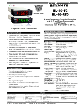
Functional Diagram
Pinout Diagram
The Rear View of the Meter diagram shows the meter with the
relay configuration: dual 9 Amp Form C and dual 4 Amp Form
A relays� An analog output module is also shown as installed�
The CL-B101D40-TCRTD uses plug-in type screw terminal con-
nectors for all input and output connections� The power supply
connections (pins 14 and 15) have a unique plug and socket out-
line to prevent cross connection� The main board and input signal
conditioner use right-angled connectors as standard� The output
module uses straight-thru connectors as standard�
WARNING: AC and DC input signals and power supply
voltages can be hazardous. Do Not connect live wires to
screw terminal plugs, and do not insert, remove or handle
screw terminal plugs with live wires connected.
Standard plug-in screw terminal connectors provided by Texmate:
Connector Pinouts
Connector Pinouts
Input Signal – Pins 1 to 6
Pins 1 to 6 are reserved for the input signal conditioner�
See the data sheet for the selected input signal conditioner�
Pins 8 to 11 – Rear Panel Function Pins
Pins 8 to 11 provide functions that can be implemented
with an external switch. Their pin definitions are:
Pin 11 DIM. By connecting the display dim (DIM) pin to
the COMMON pin, the display brightness setting
is halved�
Pin 10 COMMON. To activate the LOCK or DIM
functions from the rear of the meter, the
respective pins have to be connected to the
COMMON pin� This pin is connected to the
internal power supply ground�
Pin 9 No function
Pin 8 LOCK. By connecting the LOCK pin to the
COMMON pin, the meter's programmed
parameters can be viewed but not changed�
17 16
14 158 9 10 11
See Leopard Family Input
Signal Conditioning Modules
1 2 3 4 5 6
21 20 19
Relay Outputs Reserved for RS-485
LOCK
COMMON
No Function
DIM
ANALOG
OUTPUT –
AC
Neutral
– DC
AC
Line
+ DC
ANALOG
OUTPUT +
29 28 27 26 25 24 23 22
Auto-sensing AC/DC power supply� For voltages between
85-265 V AC / 95-300 V DC (PS1) or 18-48 V AC / 10-72 V DC (PS2).

CL-B101D40-TCRTD Manual (d0099) Page 11
29 28 27 2526 24 23 22
DL Series
Options
4A
4A
Order Code
OR11
OR12
OR23
OR14
-
-
-
-
-
-
-
4A
4A
4A
4A
10A -
-
OR15
OR16
SP2 SP4 SP1 SP3
9A
9A
9A
9A
9A
9A
9A
9A
SP3SP1SP4SP2
Relay Modules with 2 Non-Isolated 4A Form A Relays,
and 2 Non-Isolated 9A Form C Relays
29 28 27 2526 24 23 22
DL Series
OptionsOrder Code
OR51
OR52
OR53
OR54
-
-
-
- -
-
210mA
210mA210mA
210mA210mA210mA
210mA210mA210mA210mA
SP4 SP3 SP2 SP1
SP4 SP3 SP2 SP1
Relay Modules with 4 Independent 300V
(210mA DC only)
29 28 27 2526 24 23 22
DL Series
OptionsOrder Code
OR31
OR32
OR33
OR34
-
-
-
- -
-
5A5A 5A 5A
5A 5A
5A
5A
5A
5A
SP4 SP3 SP2 SP1
SP1SP2SP3SP4
Relay Modules with 4 Isolated 5A Form A Relays
Output
Carrier
Board
Output
Carrier
Board
Relay
Module
Relay
Module
Input Signal
Conditioner
Analog Output
Module
Main
Board
Display
Board
Component Layout
Component Layout
Connector Pinouts continued
AC/DC Power Input- Pins 14 and 15
Auto-sensing AC/DC power supply� For voltages between
85-265 V AC/95-300 V DC (PS1) or 18-48 V AC/10-72 V DC (PS2).
Pin 14 AC/DC Neutral. Neutral power supply line�
Pin 15 AC/DC line. Live power supply line�
Optional Carrier Board Output Pins
Analog Output- Pins 16 and 17
Pins 16 and 17 are the analog output pins on the optional
output module� Their pin definitions are:
Pin 16 Positive (+) analog output�
Pin 17 Negative (–) analog output�
Pins 22 to 29 – Output Module Pins

Page 12 CL-B101D40-TCRTD Manual (d0099)
101.60
4.000
42.85
1.687
42.85
1.687
42.85
1.687
42.85
1.687
6.50
0.256
113.79
4.480
113.79
4.480
56.90
2.240
56.90
2.240
17.50
0.689
97.77
3.849
119.70
4.713
13.70
0.539
1/4"-28UNF
Panel Cutout
5.0
0.197
R4
0.157
16.30
0.642
13.70
0.539
4.80
0.189
screw-10-32 UNF
8
0.315
7
0.276
16.30
0.642
13.70
0.539
2.60
0.102
6.32
0.249
screw-1/4”-28 UNF
Case Dimensions
IT11
:
RTD, 100Ω Pt. Select 3/4-wire,°C/°F, 1°/0.1°
IT15: RTD, 1000Ω Pt. Select 3/4-wire,
°C/°F, 1°/0.1°
Lead Resistance Compensation
RTD
Pt-100Ω
RTD
3 wire
4 wire
Excitation is 1mA. Up to 50Ω resistance
in each lead can be compensated
Typical accuracy is
±(0.05% + 2 digits)
LINEARISATION IS DIGITAL
LEOPARD
167G
BL-40H
DL-40H
FL-B101D40H
IT10 Thermocouple Input Signal Conditioner installed.
1� The cold junction select header must be installed in the
correct position for the thermocouple type to be used�
Thermocouple types J, K, R and T are supported� If you
wish to use a different thermocouple from the default setting
of K/T it is necessary to remove the module and move the
cold junction select header to the appropriate position�
2� Unplug the connector plugs from the meter� Remove the
case back panel and slide the module out of the case�
3. After selecting the appropriate header position, insert the
module back into the case� Snap the back panel back into
the case� Apply power to the meter�
4� Enter the program mode and select the type of thermocouple
(J, K, R, T), the resolution (0�1° or 1°) and the display units
·°C or °F)� See Page 4 of the data sheet for details�
5� Connect a thermocouple simulator to the meter inputs�
Apply an input corresponding to 0° and adjust the ZERO
Potentiometer to make the display read 0�
6. Apply an input corresponding to the maximum reading of
the thermocouple and adjust the SPAN Potentiometer to
make the display read correctly�
7� The meter is now calibrated and ready for use� Calibration
will have to be performed again if the thermocouple type is
changed�
IT11 or IT15 RTD Input Signal Conditioner installed.
1. Enter the program mode and select the type of RTD (385
or 392 curve and 3-wire/ 4-wire), the resolution (0.1° or
1°) and the display units ·°C or °F)� See Page 4 of the data
sheet for details�
2� Connect an RTD simulator to the meter inputs� Apply an input
corresponding to 0° and adjust the ZERO Potentiometer to
make the display read 0�
3. Introduce a lead resistance of 10Ω in each lead. Adjust the
Lead Resistance Compensation potentiometer to make the
display again read 0�
4� The meter is now calibrated and ready for use� Calibration
will have to be performed again if the RTD type is changed�
Input Module Calibration Procedure
IT10: Thermocouple, J/K/R/T, Selectable ˚C/˚F,
1˚/0.1˚
R
K/T
J
T/C +
J/K/R/T THERMOCOUPLE
T/C −
LINEARISATION IS DIGITAL
BL-40H
DL-40H
FL-B101D40H
LEOPARD
153A
Cold Junction Thermocouple
Type Select Header

CL-B101D40-TCRTD Manual (d0099) Page 13
BASIC MODEL #
DISPLAY
POWER SUPPLY INPUT MODULES ANALOG OUTPUT RELAY OUTPUT OPTIONS / ACCESSORIES
OA____
CL-B101D40-TCRTD
Add to the basic model number the order code suffix for each standard option required. The last suffix is to
indicate how many different special options and or accessories that you may require to be included with this product.
Ordering Example: CL-B101D40-TCRTD-VRR-PS1-IA01-OIC-R11-OA2 plus ZR
Ordering Information
WARRANTY
Texmate warrants that its products are free from defects in material and workmanship under
normal use and service for a period of one year from date of shipment. Texmate’s obligations
under this warranty are limited to replacement or repair, at its option, at its factory, of any of
the products which shall, within the applicable period after shipment, be returned to Texmate’s
facility, transportation charges pre-paid, and which are, after examination, disclosed to the
satisfaction of Texmate to be thus defective. The warranty shall not apply to any equipment
which shall have been repaired or altered, except by Texmate, or which shall have been
subjected to misuse, negligence, or accident. In no case shall Texmate’s liability exceed the
original purchase price. The aforementioned provisions do not extend the original warranty
period of any product which has been either repaired or replaced by Texmate.
USER’S RESPONSIBILITY
We are pleased to offer suggestions on the use of our various products either by way of
printed matter or through direct contact with our sales/application engineering staff. However,
since we have no control over the use of our products once they are shipped, NO WARRANTY
WHETHER OF MERCHANTABILITY, FITNESS FOR PURPOSE, OR OTHERWISE is made
beyond the repair, replacement, or refund of purchase price at the sole discretion of Texmate.
Users shall determine the suitability of the product for the intended application before using,
and the users assume all risk and liability whatsoever in connection therewith, regardless
of any of our suggestions or statements as to application or construction. In no event shall
Texmate’s liability, in law or otherwise, be in excess of the purchase price of the product.
Texmate cannot assume responsibility for any circuitry described. No circuit patent or soft-
ware licenses are implied. Texmate reserves the right to change circuitry, operating software,
specifications, and prices without notice at any time.
1934 Kellogg Ave., Carlsbad, CA 92008
Tel: 1-760-598-9899 • 1-800-TEXMATE
Fax: 1-760-598-9828 • Email: [email protected]
CL-B101D40-TCRTD Technical Manual Copyright © 2020 Texmate Inc. All rights
reserved. Published by: Texmate Inc. USA. Information in this Technical Manual
is subject to change without notice due to correction or enhancement. The
information described in this manual is proprietary to Texmate, Inc. and may
not be copied, reproduced or transmitted, in whole or in part, in connection with
the design, manufacture, or sale of apparatus, device or private label product
without the express written consent of Texmate, Inc.
BASIC MODEL NUMBER
CL-B101D40-TCRTD
114x114mm, 101 Segment 235º Circular Bargraph
with 4 Digit Display
Standard Options for this Model Number
Order Code Suffix Description List
DISPLAY
RR......Red Circular 101 Segment LED Bar with 4 Digit Red LED Display ........N/C
GR ...
Green Circular 101 Segment LED Bar with 4 Digit Red LED Display .....
TR ......Tri-Color
Circular 101 Segment LED Bar with 4 Digit Red LED Display
....
POWER SUPPLY
PS1 .....85-265VAC/95-300VDC ...........................................N/C
PS2 .....18-48VAC/10-72VDC . . . . . . . . . . . . . . . . . . . . . . . . . . . . . . . . . . . . . . . . . . . . . .
INPUT MODULES
(Partial List. See www.texmate.com)
IT10.....Thermocouple, J/K/R/T, Selectable °C/°F, 1°/0.1° .......................
IT11.....RTD, 100Ω Pt. Selectable 3/4-wire,°C/°F, 1°/0.1°, 385/392 ................
IT15.....RTD, 1000Ω Pt. Selectable 3/4-wire,°C/°F, 1°/0.1°, 385/392 ...............
ANALOG OUTPUT
Note: If a meter is ordered with a Analog Output and/or Relay Output
Module, an Output Module Carrier Board will be automatically added to the
order.
OIC .....Isolated 16 Bit Current Output, 4-20mA ...............................
OIV .....Isolated 16 Bit Voltage Output, 0-10VDC ..............................
SA-CLCB Output Module Carrier Board .......................................
RELAY OUTPUT MODULES
Note: If a meter is ordered with a Analog Output and/or Relay Output
Module, an Output Module Carrier Board will be automatically added to the
order.
SA-CLCB �������������������������������������������������
Output Module Carrier Board ����������������������������������
OR11 � One 10 Amp Form C Relay, Isolated ���������������������
OR15 � One 10 Amp Form C and Two 5 Amps Form A Relays �������
OR16 � One 10 Amp Form C and One 5 Amp Form A Relays ��������
OR12 � Two 10 Amp Form C Relays, Isolated ��������������������
OR14 � Two 10 Amp Form C and Two 5 Amps Form A Relays �������
OR23 � Two 10 Amp Form C and One 5 Amp Form A Relay, Isolated ��
OR25 � One 9A Form C & two 4A Form A relays� Isolated� ����������
OR31 � One 5 Amp Form A Relay, Isolated ����������������������
OR32 � Two 5 Amp Form A Relays, Isolated ���������������������
OR33 � Three 5 Amp Form A Relays, Isolated ��������������������
OR34 � Four 5 Amp Form A Relays, Isolated ���������������������
Solid State Relay (SSR) Output Modules DC Only
OR51 � One 400V DC Solid State Relay (SSR) 210mA �������������
OR52 � Two 400V DC Solid State Relays (SSR) 210mA ������������
OR53 � Three 400V DC Solid State Relays (SSR) 210mA�����������
OR54 � Four 400V DC Solid State Relays (SSR) 210mA ������������
Special Options and Accessories
Part Number Description List
SPECIAL OPTIONS
(Specify Inputs or Outputs & Req. Reading
)
ZR ............... Range change from Standard Range shown in BOLD Type .......$20
ZS ............... Custom Digital Display Scaling within Stadard Ranges ...........$24
CS-BAR .......... Custom Bargraph Display Scaling within Standard Range .........$17
ZS-AO............ Custom Scaling of Analog Output ...........................$35
ART-FS1 .......... Produce and install custom faceplate per meter - 1 color .........$55
ART-FS2 .......... Produce and install custom faceplate per meter - 2 color .........$60
ART-FS3 .......... Produce and install custom faceplate per meter - 3 color .........$65
ART-FS4 .......... Produce and install custom faceplate per meter - 4 color ........$69
ART-NRC-DEC ..... NRC for Artwork & set-up Custom Faceplate and/or Descriptor ....$100
ACCESSORIES
(Specify Serial # for Custom Artwork Installation)
93-PLUG2P-DP...... Extra Screw Terminal Conn., 2 Pin Power Plug ............... $3
93-PLUG2P-DR ..... Extra Screw Terminal Conn., 2 Pin Plug..................... $3
93-PLUG3P-DR ..... Extra Screw Terminal Conn., 3 Pin Plug..................... $5
93-PLUG4P-DR ..... Extra Screw Terminal Conn., 4 Pin Plug..................... $6
93-PLUG5P-DR ..... Extra Screw Terminal Conn., 5 Pin Plug..................... $7
Installation Guidelines
1� Install and wire meter per local applicable codes/regulations, the
particular application, and good installation practices�
2. Install meter in a location that does not exceed the maximum operat-
ing temperature and that provides good air circulation�
3. Separate input/output leads from power lines to protect the meter
from external noise. Input/output leads should be routed as far away as
possible from contactors, control relays, transformers and other noisy
components� Shielding cables for input/output leads is recommended
with shield connection to earth ground near the meter preferred�
4� A circuit breaker or disconnect switch is required to disconnect power
to the meter. The breaker/switch should be in close proximity to the
meter and marked as the disconnecting device for the meter or meter
circuit� The circuit breaker or wall switch must be rated for the applied
voltage (e�g�, 120VAC or 240VAC) and current appropriate for the elec-
trical application (e�g�, 15A or 20A)�
5� See Case Dimensions section for panel cutout information�
6� See Connector Pinouts section for wiring�
7. Use 28-12 AWG wiring, minimum 90˚C (HH) temperature rating. Strip
wire approximately 0.3 in. (7-8 mm).
8� Recommended torque on all terminal plug screws is 4�5 lb-in (0�51
N-m)�
/