Page is loading ...

Page 1
DIRECT VENT ZERO
CLEARANCE GAS FIREPLACE
HEATER MODEL SERIES:
MULTIFUNCTION
REMOTE (MF)
DVLL48SP90K(N,P)-1
UL FILE NO. MH30033
This appliance may be installed in an aftermarket,
permanently located, manufactured home (USA
only) or mobile home, where not prohibited by
local codes.
This appliance is only for use with the type of
gas indicated on the rating plate.
This appliance is not convertible for use with
other gases, unless a certied kit is used.
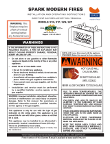
WARNING
If not installed, operated and maintained in
accordance with the manufacturer’s instructions,
this product could expose you to substances in
fuel or from fuel combustion which can cause
death or serious illness.
WARNING
FIRE OR EXPLOSION HAZARD
Failure to follow safety warnings exactly
could result in serious injury, death or
property damage.
— Do not store or use gasoline or other
ammable vapors and liquids in the
vicinity of this or any other appliance.
— WHAT TO DO IF YOU SMELL GAS
• Do not try to light any appliance.
• Do not touch any electrical switch;
do not use any phone in your building.
• Leave the building immediately.
• Immediately call your gas supplier
from a neighbor’s phone. Follow
the gas supplier’s instructions.
• If you cannot reach your gas
supplier, call the re department.
— Installation and service must be
performed by a qualied installer,
service agency or the gas supplier.
HOT GLASS
DO NOT TOUCH
NEVER
WILL
CAUSE BURNS.
GLASS
UNTIL COOLED.
ALLOW CHILDREN
TO TOUCH GLASS.
WARNING
A barrier designed to reduce the risk of burns from the
hot viewing glass is provided with this appliance and shall
be installed for the protection of children and other at-risk
individuals.
NOTICE: Barrier required, may be sold separately.
INSTALLER:
Leave this manual with the appliance.
CONSUMER:
Retain this manual for future reference.
GAS-FIRED
INSTALLATION INSTRUCTIONS
AND OWNER'S MANUAL

41370-0-0120Page 2
TABLE OF CONTENTS
Attention Installer ...........................................................................................................................3
Introduction ....................................................................................................................................4
Before You Start....................................................................................................................... 5 - 6
Carton Contents & Hardware Pack................................................................................................7
Specications.................................................................................................................................8
Accessories ...................................................................................................................................9
Orientation Of Fireplace...............................................................................................................10
Fireplace Dimensions (Indoor Application) ..................................................................................11
Clearances (Indoor Application)...................................................................................................12
Fireplace Dimensions (W/DFED489SS) ......................................................................................13
Clearances (W/DFED489SS) ......................................................................................................14
Locating Fireplace .......................................................................................................................15
Vent Termination Clearances ............................................................................................... 16 - 17
Gas Supply .......................................................................................................................... 18 - 19
Safety Information For Users of Propane Gas.............................................................................20
Electrical Connections ......................................................................................................... 21 - 22
Component Wiring Diagram ........................................................................................................23
Installation............................................................................................................................ 24 - 29
Vent System Identication ...........................................................................................................30
Venting Fireplace ................................................................................................................. 31 - 32
Venting (Horizontal) .....................................................................................................................33
Venting - Horizontal Termination ..................................................................................................34
Top Vent - Vertical Termination ....................................................................................................35
Vertical Termination ............................................................................................................. 36 - 37
Dvvk-5F Flex Vent Instructions ............................................................................................ 38 - 39
Framing And Finishing ......................................................................................................... 40 - 41
Liner Installation...........................................................................................................................42
Glass Placement..........................................................................................................................43
Multifunction Remote Operating Instructions ....................................................................... 44 - 51
Control System Troubleshooting.......................................................................................... 52 - 53
Lighting Instructions .....................................................................................................................54
Parts List ......................................................................................................................................56
Parts View ....................................................................................................................................57
Maintenance And Service .................................................................................................... 58 - 60
Important Safety Information .......................................................................................................61
Fireplace Service History .............................................................................................................62
Requirements For Massuchusetts ...............................................................................................63
Master Parts Distributor List ........................................................................................................64
How To Order Repair Parts ..........................................................................................................64
Warranty ......................................................................................................................................65
SECTION PAGE

41370-0-0120 Page 3
ATTENTION INSTALLER:
Fireplace Installation Checklist
Use this checklist in conjunction with the instructions in this manual.
Customer: _____________________________________
Lot/Address: ___________________________________
_______________________________________________
Model: ________________________________________
Serial # ________________________________________
Date Installed: __________________________________
Fireplace Location: ______________________________
Installer: _______________________________________
Dealer Phone #: _________________________________
_______________________________________________
Empire recommends the following:
• Keep this checklist visible on the replace until the installation is complete.
• Photograph the installation and copy this completed checklist for your le.
Comments: Further description of the issues, who is responsible (Installer/Builder/Other) and corrective action needed:
___________________________________________________________________________________________________________
Comments communicated to party responsible _____________________by _____________________ on ______________________
FIREPLACE INSTALLATION COMMENTS
Veried clearances to combustibles (page 14) ..................................................................... o ____________________
Fireplace is leveled and secured .......................................................................................... o ____________________
VENTING
Venting conguration complies to vent diagrams (page 29) ................................................. o ____________________
Venting installed, locked, secured in place with correct clearance ....................................... o ____________________
Firestops installed................................................................................................................. o ____________________
Exterior wall/roof ashing installed and sealed..................................................................... o ____________________
Terminations installed and sealed (pages 34-36) ................................................................. o ____________________
Light unit and test venting before enclosing the replace .................................................... o ____________________
ELECTRICAL (Pages 19-21)
Unswitched power (110-120 VAC) provided to the replace ................................................ o ____________________
GAS (Pages 17-18)
Proper appliance for fuel type............................................................................................... o ____________________
Was a conversion performed? .............................................................................................. oYes oNo
Leak check performed and inlet pressure veried ................................................................ o ____________________
FINISHING (Pages 23-24)
Non-combustible board installed .......................................................................................... o ____________________
Veried all clearances meet installation manual requirements ............................................. o ____________________
Mantels and wall projections meet requirements ................................................................. o ____________________
Finishing complies with clearance requirements .................................................................. o ____________________
Barrier for glass front properly installed ................................................................................ o ____________________
FIREPLACE SETUP
All packaging and protective materials removed (inside & outside of replace) .................. o ____________________
Media installed correctly ....................................................................................................... o ____________________
Firebox glass doors cleaned, installed, and secured............................................................ o ____________________
Accessories installed properly .............................................................................................. o ____________________
Started Fireplace and veried no gas leaks exist ................................................................. o ____________________
Manual envelope and all of its contents removed from inside/outside the
replace and given to party responsible for use and operation ............................................
o ____________________

41370-0-0120Page 4
Instructions to Installer
1. Leave instruction manual with owner.
2. Have owner complete the Product Registration Card
supplied with the replace or register online.
3. Show owner how to start and operate the replace.
This direct-vent gas replace heater is designed to operate with
all combustion air being siphoned from the outside of the building
and all exhaust gases expelled to the outside of the building. The
information contained in this manual pertains to all models and
gas control systems unless otherwise noted.
Appliance Certication
WARNING
This replace is not for use with solid fuels. Burning solid
fuels could cause personal injury or property damage.
This replace is design certied in accordance with American
National Standard/CSA Standard ANSI Z21.88/CSA 2.33 and by
Underwriters Laboratories as a Direct-Vent Gas Fireplace Heater
and shall be installed according to these instructions.
Consult your local building code agency, prior to installation,
to ensure compliance with local codes-including permits and
inspections.
The replace, when installed, must be electrically grounded in
accordance with local codes or, in absence of local codes, with
the National Electric Code ANSI/NFPA 70 or Canadian Electric
code, CSA C22.1, if an external electrical source is utilized.
These models may be installed in a bedroom or bed-sitting room
in the U.S.A. and Canada.
Qualied Installing Agency
Installation and replacement of gas piping, gas utilization
equipment or accessories and repair and servicing of equipment
shall be performed only by a qualied agency. The term “qualied
agency” means any individual, rm, corporation or company
which either in person or through a representative is engaged
in and is responsible for (a) the installation or replacement of
gas piping or (b) the connection, installation, repair or servicing
of equipment, who is experienced in such work, familiar with all
precautions required and has complied with all the requirements
of the authority having jurisdiction.
Commonwealth of Massachusetts: The installation must be
made by a licensed plumber or gas tter in the Commonwealth
of Massachusetts.
WARNING
ANY CHANGE TO THIS FIREPLACE OR ITS CONTROLS
CAN BE DANGEROUS.
Improper installation or use of the replace can cause serious
injury or death from re, burns, explosions, or carbon monoxide
poisoning.
The installation must conform with local codes or, in the absence
of local codes, with the National Fuel Gas Code ANSI Z223.1/
NFPA 54* Natural Gas and Propane Installation Code, or CSA
B149.1 in Canada. *Available from the American National
Standards Institute, Inc. 11 West 42nd St., New York, N.Y. 10036.
Any alteration of the original design, installation other than
as shown in these instructions or use with a type of gas not
shown on the rating plate is the responsibility of the person
and company making the change.
NOTICE: All correspondence should refer to complete Model
Number, Serial Number and type of gas.
High Altitude
When installing this replace at an elevation above 2000 feet
(in the United States) it may be necessary to decrease the input
rating by replacing the existing burner orice with a smaller size.
Generally, you should be reduce input by 4 percent for each 1000
feet above sea level. However, if the heating value of the gas has
been reduced, this may not apply. Check with Empire Comfort
Systems for proper orice size identication.
Canadian High Altitude
Altitude: 0-4500 feet (0-1370 m)
When installing this replace at an elevation above 4500 feet (in
Canada), check with Empire Comfort Systems for assistance in
determining the proper orice for location.
INTRODUCTION

41370-0-0120 Page 5
BEFORE YOU START
UNPACKING THE FIREPLACE
1. Cut binding straps and shrink wrap.
2. Remove top board and corner posts.
3. Lift replace from the pallet and place it near installation site.
4. Remove non-combustible boards from pallet and set aside.
5. Verify that the replace and components have not been
damaged during shipping.
6. Using list on page 56 verify that you have all components
that shipped with replace.
TELEVISION CONSIDERATIONS
Installing a television above a replace has become increasingly
popular; however, the area above any replace gets hot and most
TV manufacturers recommend against placing their products
near a heat source.
If you install a television above this replace, Empire Comfort
Systems accepts no responsibility for damage or injuries. Follow
the television manufacturer’s installation instructions, including
any recommendations regarding proximity to heat sources.
If you have a TV above your replace, turn off the replace and
let it cool completely before servicing or touching any buttons
on the TV.
SAMPLE WARNINGS AND DEFINITIONS:
DANGER
Indicates a hazardous situation which, if not avoided, will
result in death or serious injury.
WARNING
Indicates a hazardous situation which, if not avoided, could
result in death or serious injury.
CAUTION
Indicates a hazardous situation which, if not avoided, could
result in minor or moderate injury.
NOTICE: Addresses practices not related to personal injury.
____________________________________________________
This direct-vent gas replace and its components are tested
and safe when installed in accordance with this installation
manual. Report to your dealer any parts damaged in shipment,
specically check glass for chips or cracks. Do not install
replace with damaged, incomplete, or substitute parts.
Read all instructions before starting installation and follow
them carefully to ensure safe operation. Failure to follow the
instructions will void the warranty and may cause a re hazard.
The warranty will be voided by, and the warrantor disclaims
any responsibility for the following actions:
• Installation by anyone other than the dealer or his agent.
• Installation of any damaged replace or component.
• Modication of the replace or Direct-Vent system.
• Installation other than as instructed by Empire Comfort
Systems.
• Improper positioning of logs, glass door, or accessories.
• Installation and/or use of any component part not
manufactured or approved by Empire Comfort Systems.
All correspondence should refer to complete Model Number, Serial
Number and type of gas. Fill out the Homeowner Reference Section.
See page 3.

41370-0-0120Page 6
BEFORE YOU START (CONT’D)
PREPARATION
This replace and its components are safe when installed in
accordance with this manual.
INSTALLATION CONSIDERATIONS
• Gas supply piping – right side entrance - See page 10.
• Electrical supply and connections 120V, 60Hz, 1 Amp,
right side entrance - See page 10.
• Allowable replace mounting surfaces:
1. A hard, at, combustible or non-combustible surface
2. A raised platform of combustible or non-combustible
material.
3. The four corners of the replace on non-combustible
material – such as cinder blocks (where allowed by local
codes) – so that contact is made on all four perimeter
edges on the bottom of the replace.
• If the replace is installed directly on carpeting, tile or other
combustible material other than wood ooring, install a metal
or wood panel underneath extending the full width and depth
of the replace.
• This replace is designed to be installed in a zero-clearance
enclosure. Combustible material can come in contact with
the side standoff spacers, and the replace can be secured
to combustible framing with the framing brackets provided.
PLANNING THE INSTALLATION
Determine where the replace will be located and what
accessories will be installed.
Your location must allow for:
• Venting – either vertical or horizontal.
• Choose a vent conguration. See pages 34-36 and make
sure the required access through attics and walls is not
blocked by other utilities such as water lines, sewer vents,
gas lines, etc. If access is blocked, move the utilities or
relocate the replace.
• Gas supply piping (right side entrance) - See pipe size and
specs on page 17.
• Electrical supply requirements (120V, 60Hz, 1 Amp) - right
side entrance - See page 10.
• Proper framing required for replace installation.
See page 22.
• Finishing the replace – drywall thickness, tile or stone
thickness, and desired decorative accessories can affect
how you frame the openings and how you attach the nailing
anges to set the proper depth. See pages 23 - 24 for
nishing details, before you begin.
ACCESSORIES
Accessories for this appliance must be installed after tting the
replace into the framed opening (excluding the DFED489SS
wall kit, which must be installed prior).

41370-0-0120 Page 7
CARTON CONTENTS & HARDWARE PACK
Items not shown to scale.
INDEX
NUMBER
DESCRIPTION
QUANTITY
SUPPLIED
1
Door Removal Tool (attached to
replace)
1
2 Product Registration Card 1
3 AA Battery 4
4 AAA Battery 3
5 Cover Plate, Battery Box 1
6 Remote 1
7 Junction Box Cover 1
8 Duplex Receptacle 1
9 Flue Restrictor 1
10 Battery Box 1
*11 Wire Harness 1
A #10 x 1/2 Screw 39
** B #8 x 1 Self-Drilling Screw 36
C Nailing Flange 8
** For use in mounting non-combustible board to standoffs.
* Not shown
See Parts Lists on page 50 for ordering replacement parts. Do
not order batteries, bolts, screws, washers or nuts. They can be
purchased at your local hardware store.
1
2
3
5
6
4
7
9
8
OR
10
1
2
3
5
6
4
7
9
8
OR
10
#8 X 1” PHILLIPS SELF-DRILLING SCREW
A
B
C

41370-0-0120Page 8
SPECIFICATIONS
MODEL DVLL48NAT DVLL48LP
Input BTU/Hr Maximum 37,000 34,000
Input BTU/Hr Minimum 25,000 27,000
KWH (Maximum) 11.13 9.95
KWH (Minimum) 7.32 7.90
Orice #31 #50
Air Shutter Opening Front (inches) 1/16 Full Open
Height without standoff (inches) 34-1/2 34-1/2
Width (inches) 61-1/4 61-1/4
Depth (inches 20-1/2 20-1/2
Gas Inlet Shutoff Valve (pipe) 1/2 NPT 1/2 NPT
NOTICE: Air shutter settings are factory minimum settings. Some venting congurations may require minor air shutter adjustments for
optimum performance.
GAS SUPPLY PRESSURES (Inches water column)
Gas Type Maximum Minimum Manifold
Natural 14 4.5 3.5
Propane 14 11 10

41370-0-0120 Page 9
ACCESSORIES
ACCESSORIES
Description Model Color Used On
Trim Kit (Beveled) DF48BL Black DVLL48SP
Trim Kit (Beveled) DF48HP Pewter DVLL48SP
Window Frame (Beveled 2 inch) DF482NB Nickel DVLL48SP
Decorative Front DFF48FPD Pewter DVLL48SP
Liner Ledge Stone DVP48SLG Stone DVLL48SP
Liner Black Porcelain DVP48SLKR Black DVLL48SP
Log and Rock Set LS60THF NA DVLL48SP
SS Front (Exterior Install) DFED489SS NA DVLL48SP
Crushed Glass Media (Black) * DG1BKP Black DVLL48SP
Crushed Glass Media (Blue) * DG1BUC Blue DVLL48SP
Crushed Glass Media (Clear) * DG1CLF Clear DVLL48SP
CONVERSION KITS
Description Model Color Used On
Conversion Kit - Propane to Natural Gas 36435 NA DVLL48SP
Conversion Kit - Natural to Propane Gas 36434 NA DVLL48SP
* Six square feet required. These model numbers contain approximately one square foot each.

41370-0-0120Page 10
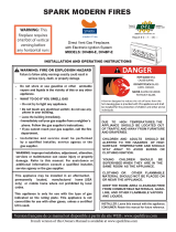
ORIENTATION OF FIREPLACE
NOTICE: When you are looking at the front side of the replace,
the pilot will be to your right on the opposite side of the burner.
The gas line access and junction box will also be on your right.
The DFED489SS Outdoor Kit may be installed only on the
back side of the replace.
The front glass frame may be removed for service. The rear glass
frame is xed in place.
Figure 1
PILOT (TOWARDS RIGHT,
BEHIND THE BURNER)
FRONT BACK (OUTDOOR KIT
INSTALLATION SIDE)
RIGHT-SIDE VIEW
VENT BIASED
TOWARDS BACK
JUNCTION BOX &
GAS-LINE BIASED
TOWARDS FRONT
BACK (OUTDOOR KIT
INSTALLATION SIDE)
FRONT
BACK (OUTDOOR KIT
INSTALLATION SIDE)
VENT BIASED
TOWARDS BACK
JUNCTION BOX &
GAS-LINE BIASED
TOWARDS FRONT
FRONT
PILOT (TOWARDS RIGHT,
BEHIND THE BURNER)
RIGHT-SIDE VIEW

41370-0-0120 Page 11
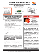
FIREPLACE DIMENSIONS (INDOOR APPLICATION)
INDEX
LETTER
DIMENSION DESCRIPTION
DIMENSIONS
IN INCHES
A The maximum height of rebox face (excluding standoffs) 34-1/2
B The maximum width of the rebox face (excluding nailing anges) 61-1/4
C The maximum depth of the rebox 20-1/2
D The height of the rebox opening 18
E The width of the rebox opening 52-1/4
F The interior depth of the rebox (not shown) 16-1/4
G The rear exterior width of the rebox NA
H The height to the rebox standoffs 52-3/8
I Width from the left side of the box to the centerline of vent 30-5/8
J Depth from back of box to centerline of top vent 8-3/4
K Height from the bottom of the box to the gas line opening 14-5/8
L Depth from the front of the box to gas line opening 14
M Depth from rear of box to gas line opening 8-1/4
N Glass height 13
O Glass width 48
P Depth from front of box to centerline of vent 11-3/4
Q Distance from oor to replace opening 7-1/2
R Height from oor to vent collar 35-7/8
S Overall height to header 51-3/4
T Distance between framing bracket ends 69
U Interior rear width of rebox (not shown) NA
V Distance from the oor to the glass opening 10-1/8
N
S
H
V
C
J
P
E
O
B
T
Q
D
A
I
K
LM
R

41370-0-0120Page 12
MANTEL CHART
INDEX
LETTER
MANTEL DEPTH
(Dimensions in inches)
A 12 27
B 10 27
C 8-3/8 24-7/8
D 6-5/8 23-5/8
E 5 20-1/2
F 3-3/8 18-3/8
G 1-5/8 16-1/8
H 0 14
Figure 5
CLEARANCES
Minimum clearance from top of replace opening to ceiling is
38 inches. Minimum clearance from side of replace opening to
adjacent sidewall is 6 inches.
6” MIN.
(20cm)
CEILING
MEASURE TO TOP OF
FIREPLACE OPENING
38” MIN
(89cm)
Figure 6
CLEARANCES (INDOOR APPLICATION)
19” MIN.
2” X 4” HEADER
STAND-OFF
FINISHED WALL
(COMBUSTIBLE)
NON-COMBUSTIBLE
BOARD
TOP FRAMING LEDGE
BARRIER
SCREEN/GLASS
FRONT
NAILING FLANGE
NON-COMBUSTIBLE
BOARD
Figure 2
NOTICE:
Use only non-combustible materials to nish the face
of the replace.
NOTICE: COMBUSTIBLE MATERIALS
ALLOWED IN SHADED AREA
Figure 3
Vent Pipe Clearance
NOTICE: Maintain 1-inch clearance around vertical vent pipe.
See Figure 4.
For horizontal vent, maintain a minimum 1-inch clearance
to the bottom and sides of the vent, and 3-inch clearance to
combustibles above the vent pipe.
1” MINIMUM CLEARANCE
AROUND VERTICAL VENT
PIPE (EXCLUDING HEADER
SHIELDS)
VENT PIPE
Figure 4

41370-0-0120 Page 13
FIREPLACE DIMENSIONS (W/DFED489SS)
NOTICE: Fireplace shown with DFED489SS outdoor kit installed.
INDEX
LETTER
DIMENSION DESCRIPTION
DIMENSIONS
IN INCHES
A The maximum height of rebox face (excluding standoffs) 34-1/2
B The maximum width of the rebox face (excluding nailing anges) 67-3/4
C The maximum depth of the rebox 22-1/4
D The height of the rebox opening 17-3/4
E The width of the rebox opening 51-3/4
F The interior depth of the rebox (not shown) 16-1/4
H The height to the rebox standoffs 52-3/8
I Width from the left side of the box to the centerline of vent 30-5/8
J Depth from back of box to centerline of top vent 10-1/2
K Height from the bottom of the box to the gas line opening 14-5/8
L Depth from rear of box to gas line opening 14
M Depth from the front of the box to gas line opening 8-1/4
N Glass height 12-1/2
O Glass width 47-1/2
P Depth from front of box to centerline of vent 11-3/4
Q Distance from oor to replace opening 7-3/4
R Height from oor to vent collar 35-7/8
S Overall height to header 51-3/4
T Distance between framing bracket ends 71
V Distance from the oor to the glass opening 10-1/2
O
OUTDOOR KIT

41370-0-0120Page 14
MANTEL CHART
TOP EDGE OF
FIREPLACE OPENING
14”
27”
12”
A
H
A
H
OUTDOOR KIT
ON “BACK SIDE”
OF UNIT
INDEX
LETTER
MANTEL DEPTH
(Dimensions in inches)
A 12 27
B 10 27
C 8-3/8 24-7/8
D 6-5/8 23-5/8
E 5 20-1/2
F 3-3/8 18-3/8
G 1-5/8 16-1/8
H 0 14
Figure 10
CLEARANCES
Minimum clearance from top of replace opening to ceiling is
38 inches. Minimum clearance from side of replace opening to
adjacent sidewall is 6 inches.
6” MIN.
(20cm)
CEILING
MEASURE TO TOP OF
FIREPLACE OPENING
38” MIN
(89cm)
Figure 11
CLEARANCES (W/DFED489SS)
19” MIN.
2” X 4” HEADER
STAND-OFF
FINISHED WALL
(COMBUSTIBLE)
NON-COMBUSTIBLE
BOARD
TOP FRAMING LEDGE
BARRIER
SCREEN/GLASS
FRONT
NAILING FLANGE
OUTDOOR KIT
ON “BACK SIDE”
OF UNIT
NON-COMBUSTIBLE
BOARD
Figure 7
NOTICE:
Use only non-combustible materials to nish the face
of the replace.
NOTICE: COMBUSTIBLE MATERIALS
ALLOWED IN SHADED AREA
Figure 8
Vent Pipe Clearance
NOTICE: Maintain 1-inch clearance around vertical vent pipe.
See Figure 9.
For horizontal vent, maintain a minimum 1-inch clearance
to the bottom and sides of the vent, and 3-inch clearance to
combustibles above the vent pipe.
1” MINIMUM CLEARANCE
AROUND VERTICAL VENT
PIPE (EXCLUDING HEADER
SHIELDS)
VENT PIPE
Figure 9

41370-0-0120 Page 15
Figure 12
NOTICE: For Room Divider installation the horizontal portion of the
vent system must not exceed 20 feet with a minimum vertical run
of 8 feet. See details in Venting Section.
NOTICE: When installing this replace against an exterior wall,
insulate to applicable insulation codes.
A peninsula room divider installation requires a minimum of 6 inches
of clearance from the perpendicular wall to the front opening of
the replace.
LOCATING FIREPLACE
PENINSULA
ROOM DIVIDER
INSTALLATION
ROOM DIVIDER
INSTALLATION
FLUSH EXTERIOR
WALL INSTALLATION
“BUMP-OUT” EXTERIOR
WALL INSTALLATION

41370-0-0120Page 16
Termination clearance for buildings with combustible and noncombustible exteriors.
Figure 13
VENT TERMINATION CLEARANCES
Vertical Sidewall Installations
Important! Minimum clearance between vent pipes and
combustible materials is 3 inches (76 mm) on top, and 1 inch
(25 mm) on bottom and sides.
Important! When vent termination exits through foundation less
than 20 inches (508 mm) below siding outcrop, the vent pipe
must extend outward so that the horizontal vent termination is
located ush to, or beyond the outcrop siding.
Information on Various Venting Routes and Components
Important: It is always best to locate the replace in such a way
that minimizes the number of offsets and horizontal vent length.
Since it is very important that the venting system maintain its
balance between the combustion air intake and the ue gas
exhaust, certain limitations as to vent congurations apply and
must be strictly adhered to.
The venting graph on page 28 shall be used to determine the
allowable vertical and horizontal vent lengths.
The horizontal vent run refers to the total length of vent pipe from
the ue collar of the replace to the face of the outer wall.
Venting termination shall not be recessed into wall or siding.
ATTENTION: Vinyl Soft, Vinyl Ceiling, Vinyl Overhang
Disclaimer
Clearances are to heat resistant material (i.e. wood, metal).
This does not include vinyl. Empire Comfort Systems Inc.
will not be held responsible for heat damage caused from
terminating under vinyl overhangs, vinyl ceilings or vinyl
ventilated/unventilated softs.
RECESSED LOCATION
OUTSIDE CORNER
INSIDE CORNER
“A”= COMBUSTIBLE 9” (229mm)
= NONCOMBUSTIBLE 2” (51mm)
“F”= COMBUSTIBLE 6” (152mm)
= NONCOMBUSTIBLE 6” (152mm)
BALCONY
WITH PERPENDICULAR SIDE WALL
BALCONY
WITH NO SIDE WALL
“C”= CLEARANCE FROM CORNER
IN RECESSED LOCATION
COMBUSTIBLE 9” (229mm)
NONCOMBUSTIBLE 2” (51mm)
“D”= MINIMUM WIDTH FOR BACK WALL
OF A RECESSED LOCATION
COMBUSTIBLE 38” (965mm)
NONCOMBUSTIBLE 24” (610mm)
“E”= MAXIMUM DEPTH OF 48” (1219mm)
FOR RECESSED LOCATION
“G”= COMBUSTIBLE 9” (229mm)
= NONCOMBUSTIBLE 2” (51mm)
“H”= COMBUSTIBLE 18” (457mm)
= NONCOMBUSTIBLE 12” (305mm)
“I” = COMBUSTIBLE 12” (457mm)
= NONCOMBUSTIBLE 12” (305mm)

41370-0-0120 Page 17
VENT TERMINATION CLEARANCES (CONT’D)
Canadian Installations1 US Installations2 Canadian Installations1 US Installations2
A= Clearance above grade,
veranda, porch, deck, or
balcony
12 in (30 cm) 12 in (30cm)
I= Clearance to service
regulator vent outlet 3 ft (91 cm) 6 ft
B= Clearance to window or
door that may be open
6 in (15 cm) for appli-
ances ≤ 10,000 Btu/H
(3 kW), 12 in (30 cm)
for appliances > 10,000
Btu/H (3 kW) and ≤
100,000 Btu/H (30 kW),
36 in (91 cm) for appli-
ances > 100,000 Btu/H
(30 kW)
6 in (15 cm) for appli-
ances ≤ 10,000 Btu/H (3
kW), 9 in (23 cm) for ap-
pliances > 10,000 Btu/H
(3 kW) and ≤ 50,000
Btu/H (15 kW), 12 in
(30 cm) for appliances >
50,000 Btu/H (15 kW)
J= Clearance to nonme-
chanical air supply
inlet to building or the
combustion air inlet to
any other appliance
6 in (15 cm) for appli-
ances ≤ 10,000 Btu/H
(3 kW), 12 in (30 cm)
for appliances > 10,000
Btu/H (3 kW) and ≤
100,000 Btu/H (30 kW),
36 in (91 cm) for appli-
ances > 100,000 Btu/H
(30 kW)
6 in (15 cm) for appli-
ances ≤ 10,000 Btu/H (3
kW), 9 in (23 cm) for ap-
pliances > 10,000 Btu/H
(3 kW) and ≤ 50,000
Btu/H (15 kW), 12 in (30
cm) for appliances >
50,000 Btu/H (15 kW)
C= Clearance to
permanently
closed window
12 in (30 cm) 12 in (30 cm)
K= Clearance to a mechani-
cal air supply inlet 6 ft (1.83 m)
3 ft (91 cm) above if
within 10 ft (3 m) hori-
zontally
D= Vertical clearance
ventilated soft located
above the terminal within
a horizontal distance of 2
feet (61 cm) from the
center line of the terminal
24 in (61 cm) 24 in (61 cm)
L= Clearance above paved
sidewalk or paved drive-
way located on public
property
7 ft (2.13 m) † 7 ft (2.13 m) †
E= Clearance to
unventilated soft 12 in (30 cm) 12 in (30 cm)
M= Clearance under
veranda, porch deck,
or balcony
12 in (30 cm) ‡ 12 in (30 cm) ‡
F= Clearance to outside
corner
6 in (15 cm) 6 in (15 cm)
1 In accordance with the current CSA B149.1, Natural Gas and Propane Instal-
lation Code
G= Clearance inside corner
9 in (23 cm) 9 in (23 cm)
2 In Accordance with the current ANSI Z223.1/NFPA 54, National Fuel Gas
Code
H= Clearance to each side
of center line extended
above meter/regulator
assembly
3 ft (91 cm) within a
height 15 ft (4.5 m)
above the meter/regula-
tor assembly
3 ft (91 cm)
† A vent shall not terminate directly above a sidewalk or paved driveway that is
located between two single family dwellings and serves both dwellings
ATTENTION: Vinyl Soft, Vinyl Ceiling, Vinyl Overhang
Disclaimer
Clearances are to heat resistant material (i.e. wood, metal). This
does not include vinyl. Empire Comfort Systems Inc. will not be held
responsible for heat damage caused from terminating under vinyl
overhangs, vinyl ceilings or vinyl ventilated/unventilated softs.
‡ Permitted only if veranda,, porch, deck, or balcony is fully open on a minimum
of two sides beneath the oor.
* For clearances not specied in ANSI Z223.1/NFPA 54 or CSA B149.1, one of
the following shall be indicated:
Clearance in accordance with local installation codes and the requirements of the
gas supplier.

41370-0-0120Page 18
GAS SUPPLY
The gas pipeline can be brought in through the right side of the
replace. Consult the current National Fuel Gas Code, ANSI
Z223.1 CAN/CGA-B149 (.1 or .2) installation code.
NOTICE: Never use plastic pipe. Check to conrm whether your
local codes allow copper tubing or galvanized.
NOTICE: Because some municipalities have additional local
codes, consult your local authority and installation code.
The following gas connectors are recommended:
— ANSI Z21.24 Appliance Connectors of Corrugated Metal
Tubing and Fittings.
— ANSI Z21.45 Assembled Flexible Appliance Connectors of
Other Than All-Metal Construction
The above connectors may be used if acceptable by the authority
having jurisdiction. The Commonwealth of Massachusetts
requires that a exible appliance connector cannot exceed three
feet in length.
Figure 14
Gas Supply Pressure (inches w.c.)
Minimum Normal Maximum
Natural Gas 4.5 7.0 14.0
Propane Gas 10.8 11.0 14.0
Manifold Pressure (inches w.c.)
Normal (HI)
Natural Gas 3.5
Propane Gas 10.0
A gas valve and ground joint union should be installed in the gas
line upstream of the gas control to aid in servicing. It is required
by the National Fuel Gas Code that a drip leg be installed near the
gas inlet. See Figure 15. This should consist of a vertical length
of pipe tee connected into the gas line that is capped on the
bottom in which condensation and foreign particles may collect.
Figure 15
Installing a New Main Gas Shut-Off Valve (Check Local Code)
Each replace should have its own manual gas shut-off valve
located in the vicinity of the replace. Where none exists, or
where its size or location is not adequate, contact your local
authorized installer for installation or relocation.
Compounds used on threaded joints of gas piping shall be
resistant to the action of liqueed petroleum gases. The gas lines
must be checked for leaks by the installer. Use a soap solution
while watching for bubbles on all exposed connections. For
unexposed pipe connections conduct a pressure test. Fireplace
must be disconnected from piping at inlet of control valve and
pipe capped or plugged for pressure test.
WARNING
Never use an exposed ame to check for leaks.
WARNING
Never pressure test with replace connected; control valve
will sustain damage! To prevent damage or injury, the replace
and its individual shut-off valve must be disconnected from
supply piping system during any pressure testing of that
system at test pressures in excess of 1/2 psig (3.5 kPa).
NOTICE: The gas control is equipped with a captured screw type
pressure test point; therefore it is not necessary to provide a 1/8
inch test point up stream of the control. See Figure 16.
When using copper or ex connector use only approved ttings.

41370-0-0120 Page 19
GAS SUPPLY (CONT’D)
Checking Manifold Pressures
Both Propane and Natural Gas valves have a built-in pressure
regulator in the gas valve. Natural Gas models will have a
manifold pressure of approximately 3.5-in w.c. (.871 kPa) at the
valve outlet with the inlet pressure to the valve from a minimum
of 4.5-in w.c. (1.120 kPa) for the purpose of input adjustment to
a maximum of 14.0-in w.c. (3.484 kPa). Propane Gas models will
have a manifold pressure approximately 10.0-in w.c. (2.49 kPa)
at the valve outlet with the inlet pressure to the valve from a
minimum of 10.8-in w.c. (2.68 kPa) for the purpose of input
adjustment to a maximum of 14.0-in w.c. (3.484 kPa).
CAUTION
If the test pressure exceeds 1/2 psig (14-in w.c.) (3.5 kPa) on
the replace gas valve, it will damage the valve and result in
a hazardous condition.
GAS VALV E
OUTLET
PRESSURE
TAP
INLET
PRESSURE
TAP
Figure 16
Gas Line Connection
Remove the access panel from the right side of the replace
Figure 17 to access the gas valve, gas ex line, junction box,
and system wiring.
Attach the gas ex line to the pre-installed gas line. Refer to the
Gas Supply section in this manual for details on the installation
requirements for the gas supply line.
14 5/8
”
8 1/4”
GAS LINE
ACCESS
JUNCTION BOX
ACCESS P
ANEL
Figure 17

41370-0-0120Page 20
SAFETY INFORMATION FOR USERS OF PROPANE GAS
Propane is ammable and can cause res and explosions. In
its natural state, propane is odorless and colorless. You may
not know all the following safety precautions which can protect
both you and your family from an accident. Read them care-
fully now, then review them point by point with the members
of your household. Someday when there may not be a minute
to lose, everyone’s safety will depend on knowing exactly what
to do. If, after reading the following information, you feel you
still need more information, please contact your gas supplier.
PROPANE GAS WARNING ODOR
If a gas leak happens, you should be able to smell the gas
because of the odorant put in the Propane Gas. That’s your
signal to go into immediate action!
• Do not operate electric switches, light matches, or your phone.
Do not do anything that could ignite the gas.
• Get everyone out of the building, vehicle, trailer, or area. Do
that IMMEDIATELY.
• Close all gas tank or cylinder supply valves.
• Propane Gas is heavier than air and may settle in low areas
such as basements. When you have reason to suspect a gas
leak, keep out of basements and other low areas. Stay out until
reghters declare them to be safe.
• Use your neighbor’s phone and call a trained Propane Gas
service person and the re department. Even though you may
not continue to smell gas, do not turn on the gas again. Do not
re-enter the building, vehicle, trailer, or area.
•
Finally, let the service technician and re department check for
escaped gas. Have them air out the area before you return.
Properly trained Propane Gas service people should repair the
leak, then check and relight the gas appliance for you.
NO ODOR DETECTED - ODOR FADE
Some people cannot smell the odor of the chemical put into the
gas. You must nd out if you can smell the odorant in propane.
Smoking can decrease your ability to smell. Being around an odor
for a time can affect your sensitivity or ability to detect that odor.
Sometimes other odors in the area mask the gas odor. People may
not smell the gas odor or their minds are on something else. Thinking
about smelling a gas odor can make it easier to smell.
The odorant in Propane Gas is colorless, and it can fade under
some circumstances. For example, if there is an underground
leak, the movement of the gas through soil can lter the odorant.
Odorants in Propane Gas also are subject to oxidation. This fading
can occur if there is rust inside the storage tank or in iron gas pipes.
The odorant in escaped gas can adsorb or absorb onto or into
walls, masonry and other materials and fabrics in a room. That will
take some of the odorant out of the gas, reducing its odor intensity.
Propane Gas may stratify in a closed area, and the odor intensity
could vary at different levels. Because it is heavier than air, there may
be more odor at lower levels. Always be sensitive to the slightest gas
odor. If you detect any odor, treat it as a serious leak. Immediately
go into action as instructed earlier.
SOME POINTS TO REMEMBER
• Learn to recognize the odor of Propane Gas. Your local
Propane Gas Dealer can give you a “Scratch and Sniff” pam-
phlet. Use it to nd out what the propane odor smells like. If
you suspect that your Propane Gas has a weak or abnormal
odor, call your Propane Gas Dealer.
• If you are not qualied, do not light pilot lights, perform service,
or make adjustments to appliances on the Propane Gas system.
If you are qualied, consciously think about the odor of Propane
Gas prior to and while lighting pilot lights or performing service
or making adjustments.
• Sometimes a basement or a closed-up house has a musty
smell that can cover up the Propane Gas odor. Do not try to
light pilot lights, perform service, or make adjustments in an
area where the conditions are such that you may not detect
the odor if there has been a leak of Propane Gas.
• Odors fade, due to oxidation by rust or adsorption on walls of
new cylinders and tanks. Therefore, people should be particu-
larly alert and careful when new tanks or cylinders are placed
in service. Odor fade can occur in new tanks, or reinstalled
old tanks, if they are lled and allowed to set too long before
relling. Cylinders and tanks which have been out of service
for a time may develop internal rust which will cause odor fade.
If such conditions are suspected to exist, a periodic sniff test
of the gas is advisable. If you have any question about the
gas odor, call your Propane Gas Dealer. A periodic sniff
test of the Propane Gas is a good safety measure under
any condition.
• If, at any time, you do not smell the Propane Gas odorant and
you think you should, assume you have a leak. Then take the
same immediate action recommended above for the occasion
when you do detect the odorized Propane Gas.
• If you experience a complete “gas out,” (the container is under
no vapor pressure), turn the tank valve off immediately. If the
container valve is left on, the container may draw in some air
through openings such as pilot light orices. If this occurs, some
new internal rusting could occur. If the valve is left open, then
treat the container as a new tank. Always be sure your con-
tainer is under vapor pressure by turning it off at the container
before it goes completely empty or having it relled before it is
completely empty.
/