Page is loading ...

Installation Instructions and
Homeowner’s Manual
CERT I F I E D
D
E
S
I
G
N
C
E
R
T
I
F
I
E
D
10010618 5/08 Rev. 2
DO NOT STORE
OR USE GASOLINE OR OTHER
FLAMMABLE VAPORS AND
LIQUIDS IN THE VICINITY OF THIS
OR ANY OTHER APPLIANCE.
WHAT TO DO IF YOU SMELL GAS:
• Do not try to light any appliance.
• Do not touch any electric switch; do
not use any phone in your building.
• Immediately call your gas supplier
from your neighbor’s phone. Follow
the gas suppliers instructions.
• If you cannot reach your gas
supplier call the fire department.
WARNING!
IF THE INFORMATION IN THIS
MANUAL IS NOT FOLLOWED
EXACTLY, A FIRE OR EXPLOSION
MAY RESULT CAUSING
PROPERTY DAMAGE, PERSONAL
INJURY OR LOSS OF LIFE.
PLEASE READ THIS MANUAL
BEFORE INSTALLING AND USING
APPLIANCE
INSTALLER/CONSUMER
SAFETY INFORMATION
FOR YOUR SAFETY
Installation and service must be
performed by a qualified installer,
service agency or the gas supplier.
Builder Top Vent Direct Vent
Models: RDV4136
INSTALLER: Leave this manual with the appliance.
CONSUMER: Retain this manual for future reference.

2
RDV4136 Series Direct Vent Gas Fireplace
10010618
Installation & Operating Instructions
Important Information, Warnings, Cautions ......................................................................... 3
Requirements for the Commonwealth of Massachusetts ....................................................4
Fireplace Dimensions ..........................................................................................................5
Locating Your Fireplace .......................................................................................................6
Clearance to Combustibles ................................................................................................. 6
Mantels ...............................................................................................................................6
Hearth ...............................................................................................................................7
Framing & Finishing ............................................................................................................7
Final Finishing ..................................................................................................................... 7
Gas Specifications ...............................................................................................................7
Gas Inlet and Manifold Pressures ....................................................................................... 7
High Elevations ...................................................................................................................7
Gas Line Installation ............................................................................................................ 7
Remote ON/OFF Switch ......................................................................................................8
EB-1 Electrical Box ..............................................................................................................9
General Venting Information
General Venting Information-Termination Location .......................................................... 11
General Information on Assembling Vent Pipes ................................................................12
How to Use the Vent Graph...................................... .........................................................13
Vertical Sidewall Applications & Installation ......................................................................14
Below Grade Installations.. ................................................................................................17
Vertical Through-the-Roof Applications & Installations ...................................................... 18
Venting Components ......................................................................................................... 20
Operating Instructions
Glass Information .............................................................................................................. 21
Window Frame Assembly Removal ................................................................................... 21
Glass Cleaning .................................................................................................................. 21
Installation of Logs, Lava Rock & Ember Material ............................................................22
Flame Characteristics ........................................................................................................24
Lighting & Operating Instructions ...................................................................................... 25
Troubleshooting .................................................................................................................27
Fuel Conversion Instructions ............................................................................................. 31
Maintenance
Cleaning the Standing Pilot Control System .....................................................................33
Replacement Parts ......................................................................................................................34
Optional Accessories
Fan Kits .............................................................................................................................37
Wiring Instructions .............................................................................................................37
Ceramic Refractory Panels ...............................................................................................38
Porcelain Steel Back ......................................................................................................... 38
Remote Controls ...............................................................................................................38
Trim Kits ............................................................................................................................ 38
Warranty .......................................................................................................................................39
Energuide .....................................................................................................................................40
PLEASE READ THE INSTALLATION & OPERATING INSTRUCTIONS BEFORE USING THIS APPLIANCE.
Thank you and congratulations on your purchase of a CFM Corporation fireplace.
IMPORTANT: Read all instructions and warnings carefully before starting installation.
Failure to follow these instructions may result in a possible fire hazard and will void the warranty.
Table of Contents

3
RDV4136 Series Direct Vent Gas Fireplace
10010618
This gas fireplace should be installed by a qualified installer,
preferably NFI or WETT (Canada) certified, in accordance with
local building codes and with current CSA-B149.1 Installation
codes for Gas Burning Appliances and Equipment. For USA
Installations follow local codes and/or the current National Fuel
Gas Code. ANSI Z223.1/NFPA 54.
FOR SAFE INSTALLATION AND OPERATION PLEASE NOTE
THE FOLLOWING:
1. This fireplace gives off high temperatures and should be
located out of high traffic areas and away from furniture and
draperies.
2. Children and adults should be alerted to the hazards of the
high surface temperatures of this fireplace and should stay
away to avoid burns or ignition of clothing.
3. CAUTION: Due to high glass surface temperature chil-
dren should be carefully supervised when in the same
room as fireplace.
4. Under no circumstances should this fireplace be modified.
Parts removed for servicing should be replaced prior to
operating this fireplace again.
5. Installation and any repairs to this fireplace must be per
-
formed by a qualified installer, service agency or gas sup-
plier. A professional service person should be contacted to
Installation & Operating Instructions
Proposition 65 Warning: Fuels used in gas, wood-
burning or oil fired appliances, and the products of
combustion of such fuels, contain chemicals known to
the State of California to cause cancer, birth defects
and other reproductive harm.
California Health & Safety Code Sec. 25249.6
IMPORTANT:
PLEASE REVIEW THE FOLLOWING CAREFULLY
Remove any plastic from from parts before turning the
fireplace ON.
It is normal for fireplaces fabricated of steel to give off
some expansion and/or contraction noises during the
start up or cool down cycle. Similar noises are found
with your furnace heat exchanger or car engine.
It is not unusual for your gas fireplace to give off some
odor the first time it is burned. This is due to the curing
of the paint and any undetected oil from the manufac-
turing process.
Please ensure that your room is well ventilated-open
all windows.
It is recommended that you burn your fireplace for at least
ten (10) hours the first time you use it. If the optional fan
kit has been installed, place the fan switch in the “OFF”
position during this time.
WARNING: Check with your electronics manufacturer
before installing a television or other electronic de-
vice above this fireplace.
RDV4136
Certified To
ANSI Z21.88-2005 / CSA 2.33-2005
Vented Gas Fireplace Heaters
12. This fireplace requires adequate ventilation and combustion
air to operate properly.
13. This fireplace must not be connected to a chimney flue
serving a separate solid fuel burning fireplace.
14. When the fireplace is not in use it is recommended that the
gas control valve be left in the OFF position.
15. These units have been approved for bedroom use.
This appliance may be installed in an aftermarket
permanently located, manufactured home or mobile home,
where not prohibited by local codes.
This appliance is only for use with the type of gas indicated
on the rating plate. This appliance is not convertible for
use with other gases, unless a certified kit is used.
The RDV4136 has been approved for mobile home
installations.
�
inspect the fireplace annually. More frequent cleaning may
be required due to excess lint and dust from carpeting, bed-
ding material, etc.
6. Control compartments, burners and air passages in this fire
-
place should be kept clean and free of dust and lint. Make
sure that the gas valve and pilot light are turned off before
you attempt to clean this fireplace.
7. The venting system (chimney) of this fireplace should be
checked at least once a year and if needed your venting
system should be cleaned.
8. Keep the area around your fireplace clear of combustible
materials, gasoline and other flammable vapour and liquids.
This fireplace should not be used as a dry-ing rack for cloth
-
ing, nor should Christmas stockings or decorations be hung
on or around the fireplace.
9. Under no circumstances should any solid fuels (wood, coal,
paper or cardboard etc.) be used in this fireplace.
10. The flow of combustion and ventilation air must not be ob
-
structed in any way.
11. When the fireplace is installed directly on carpeting, vinyl tile
or any combustible material other than wood, this fireplace
must be installed on a metal or wood panel extending the
full width and depth of the fireplace.

4
RDV4136 Series Direct Vent Gas Fireplace
10010618
Installation & Operating Instructions
Requirements for the Commonwealth of
Massachusetts
All gas fitting and installation of this heater shall only be
done by a licensed gas fitter or licensed plumber.
For all side wall horizontally vented gas fueled
equipment installed in every dwelling, building or
structure used in whole or in part for residential
purposes, including those owned or operated by the
Commonwealth and where the side wall exhaust vent
termination is less than seven (7) feet above finished
grade in the area of the venting, including but not limited
to decks and porches, the following requirements shall
be satisfied:
Installation of Carbon Monoxide Detectors
At the time of installation of the side wall horizontal
vented gas fueled equipment, the installing plumber
or gas fitter shall observe that a hard wired carbon
monoxide detector with an alarm is installed on each
additional level of the dwelling, building or structure
served by the side wall horizontally vented gas fueled
equipment. It shall be the responsibility of the property
owner to secure the services of qualified licensed
professionals for the installation of hard wired carbon
monoxide detectors.
In the event that the side wall horizontally vented gas
fueled equipment is installed in a crawl space or an
attic, the hard wired carbon monoxide detector with
alarm and battery back-up may be installed on the next
adjacent floor level.
In the event that the requirements of this subdivision
can not be met at the time of completion of installation,
the owner shall have a period of thirty (30) days
to comply with the above requirements; provided,
however, that during said thirty (30) day period, a
battery operated carbon monoxide detector with an
alarm shall be installed.
Approved Carbon Monoxide Detectors
Each carbon monoxide detector as required in
accordance with the above provisions shall comply with
NFPA 720 and ANSI/UL 2034 listed and IAS certified.
Signage
A metal or plastic identification plate shall be
permanently mounted to the exterior of the building at
a minimum height of eight (8) feet above grade directly
in line with the exhaust vent terminal for the horizontally
vented gas fueled heating appliance or equipment. The
sign shall read, in print size no less than one-half (1/2)
inch in size, “GAS VENT DIRECTLY BELOW, KEEP
CLEAR OF ALL OBSTRUCTIONS”.
Inspection
The state or local gas inspector of the side wall
horizontally vented gas fueled equipment shall not
approve the installation unless, upon inspection, the
inspector observes carbon monoxide detectors and
signage installed in accordance with the provisions of
248 CMR 5.08(2)(a)1 through 4.
Exemptions
The following equipment is exempt from 248 CMR
5.08(2)(a)1 through 4:
• The equipment listed in Chapter 10 entitled
“Equipment Not Required To Be Vented” in the most
current edition of NFPA 54 as adopted by the Board;
and
• Product Approved side wall horizontally vented gas
fueled equipment installed in a room or structure
separate from the dwelling, building or structure
used in whole or in part for residential purposes.
MANUFACTURER REQUIREMENTS
Gas Equipment Venting System Provided
When the manufacturer of Product Approved side
wall horizontally vented gas equipment provides a
venting system design or venting system components
with the equipment, the instructions provided by the
manufacturer for installation of the equipment and the
venting system shall include:
• Detailed instructions for the installation of the venting
system design or the venting system components;
and
• A complete parts list for the venting system design or
venting system.
Gas Equipment Venting System NOT Provided
When the manufacturer of a Product Approved side
wall horizontally vented gas fueled equipment does
not provide the parts for venting the flue gases, but
identifies “special venting systems”, the following
requirements shall be satisfied by the manufacturer:
• The referenced “special venting system” instructions
shall be included with the appliance or equipment
installation instructions; and
• The “special venting systems” shall be Product
Approved by the Board, and the instructions for
that system shall include a parts list and detailed
installation instructions.
A copy of all installation instructions for all Product
Approved side wall horizontally vented gas fueled
equipment, all venting instructions, all parts lists
for venting instructions, and/or all venting design
instructions shall remain with the appliance or
equipment at the completion of the installation.

5
RDV4136 Series Direct Vent Gas Fireplace
10010618
Fireplace Dimensions
10618
RDV4136 specs
2/08 djt
40” (1019 mm)
-
Rough Opening Width
Rough
Opening
Height
Rough
Opening
Depth
Gas Line
Access
41” (1041 mm)
29” (740 mm)
5/8” (16 mm)
58” (1480 mm)
15”
(387 mm)
15
”
(387 mm)
5”
(133 mm)
26”
(680 mm)
7” (178 mm)
Dia.
4” (102 mm)
Dia.
5/8” (16 mm)
2”
(51 mm)
6” (168 mm)
4”
(102 mm)
32
”
(822 mm)
3” (76 mm)
1”
(25 mm)
40” (1016 mm)
36” (914 mm)
40” (1026 mm)
Recessed
Nailing Flange
10”
(276 mm)
3”
(79 mm)
Electrical
Access
40”
(1019 mm)
41” (1041 mm)
”
(168 mm)
8” (210 mm)
2"
(51 mm)
8” (210 mm)
39” (1000 mm)
36”
(918 mm)
35” (889 mm)
1”
(25 mm)
Fig. 1 Fireplace specifications and framing dimensions.

6
RDV4136 Series Direct Vent Gas Fireplace
10010618
Y
E
A
B
C
D
F
Y
B
X
LU584-1
Locating unit
2/4/99 djt
A - Flat on wall B - Cross corner C - **Island
D - *Room divider E - *Flat on wall corner F - Chase installation
Y - 6” minimum
Note (Fig. 2):
** Island (C) and Room Divider (D) installation is possible as
long as the horizontal portion of the vent system (X) does not
exceed 20’ (6m). See details in manual Venting Section.
* When you install your fireplace in(D) Room divider or (E)
Flat on wall corner positions (Y), a minimum of 6” (152mm)
clearance must be maintained from the perpendicular wall and
the front side edge of the fireplace. See (Y) in Fig. 2.
Locating Your Fireplace
Fig. 2 Locate gas fireplace.
Top of Unit to Ceiling ............................... 36” (914 mm)
Appliance
Top ..........................................................
0” (0 mm)
Bottom .....................................................
0” (0 mm)
Side .........................................................
0” (0 mm)
Back ........................................................
0” (0 mm)
Venting
Concentric sections of DV Vent
Top, bottom & sides ..............................
1” (25 mm)
Offset sections of DV Vent
Top .......................................................
2” (51 mm)
Bottom & sides ......................................
1” (25 mm)
Clearance to Combustibles
Fig. 3b Combustible mantel leg minimum installation.
CFM170
J
F
G
H
I
Mantel
Leg
CFM164a
Mantel Leg Chart
06/22/01 sta
Black
Surround
Face
CFM170
DV Builder Front
View
O
N
M
L
K
Side of
Combustion Chamber
Mantel Mantel Leg FromSide
Ref. Leg Depth Ref. of Comb. Opening
F 10” (254 mm) K 11
¹⁄₂” (292 mm)
G 8” (203 mm) L 9
¹⁄₂” (241 mm)
H 6” (152 mm) M 7¹⁄₂” (191 mm)
I 4” (101 mm) N 5¹⁄₂” (140 mm)
J 2” (51 mm) O 3
¹⁄₂” (89 mm)
A B C
D
E
V
W
X
Y
Z
Fireplace
CFM146
DV Mantel Chart
7/5/01 sta
CFM146
Mantel Chart
Mantel Shelf Mantel from Top
Ref. or Breast Plate Ref. of Comb. Chamber
Depth
V 10” (254 mm) A 19” (483 mm)
W 8” (203 mm) B 17” (432 mm)
X 6” (152 mm) C 15” (381 mm)
Y 4” (101 mm) D 13” (330 mm)
Z 2” (51 mm) E 11” (279 mm)
Fig. 3a Combustible mantel minimum installation.
Top of Combustion
Chamber
Standoff
Noncombstible Material
Framing Members
Mantels
The height that a combustible mantel is fitted above the
fireplace is dependent on the depth of the mantel. This
also applies to the distance between the mantel leg (if
fitted) and the fireplace.
For the correct mounting height and widths refer to
Figures 3a and 3b.
The fitting of a bay window trim kit does not effect
the distances and reference points referred to in the
diagram and chart.
Noncombustible mantels and legs may be installed at
any height and width around the appliance.
When using paint or lacquer to finish the mantel, such
paint or lacquer must be heat resistant to prevent
discoloration.

7
RDV4136 Series Direct Vent Gas Fireplace
10010618
A hearth is not mandatory but is recommended for
aesthetic purposes. We recommend a noncombustible
hearth which projects out 12” (305mm) or more from the
front of the fireplace.
Cold climate installation recommendation:
When installing this unit against a non-
insulated exterior wall or chase, it is
mandatory that the outer walls be insulated
to conform to applicable insulation codes.
Hearth
Noncombustible materials such as brick or tile may be
extended over the edges of the face of the appliance.
DO NOT cover any vent or grille panels.
If a Trim Kit is going to be installed on the fireplace, the
brick or tile will have to be installed flush with the edges
of the appliance.
Final Finishing
Framing and Finishing
Natural LP (Propane)
Inlet Minimum 5.5” w.c. 11.0” w.c.
Inlet Maximum 14.0” w.c. 14.0” w.c.
Manifold Pressure 3.5” w.c. 10.0” w.c.
Gas Inlet and Manifold Pressures
Check fireplace to make sure it is levelled
and properly positioned.
To mount the appliance:
1. Choose the location.
2. This unit comes with four (4) flanges pre-mounted
on both sides of the fireplace to allow two different
drywall thicknesses to be used. Flange “A” is for 1/2”
drywall while flange “B” is for 5/8” drywall.
3. Bend the desired flanges out 90° on both sides of
the fireplace. Slide the fireplace into the framed
opening until the flanges contact the front surfaces
of the framing. Level the unit and secure it firmly in
place.
Gas Specifications
Max. Min.
Gas Input Input
Model Fuel Control BTU/h BTU/h
RDV4136RN Natural Gas Millivolt Hi/Lo 24,000 15,300
RDV4136RP Propane Millivolt Hi/Lo 24,000 19,500
RDV4136IN Natural Gas 6 Volt Hi/Lo 24,000 15,300
RDV4136IP* Propane 6 Volt Hi/Lo 24,000 19,500
Gas Line Installation
High Elevations
Input ratings are shown in BTU per hour and are
certified without deration for elevations up to
4,500 feet (1,370m) above sea level.
For elevations above 4,500 feet (1,370m) in USA,
installations must be in accordance with the cur-
rent ANSI Z223.1/NFPA 54 and/or local codes hav-
ing jurisdiction.
In Canada, please consult provincial and/or local
authorities having jurisdiction for installations at
elevations above 4,500 feet (1,370m).
When purging gas line, the front window
frame must be removed.
The gas pipeline can be brought in through the rear
of the fireplace as well as the bottom. Knockouts are
provided on the bottom behind the valve to allow for the
gas pipe installation and testing of any gas connection.
It is most convenient to bring the gas line in from the
rear right side of the valve as this allows fan installation
or removal without disconnecting the gas line.
The gas line connection can be made with properly
tinned 3/8” copper tubing, 3/8” rigid pipe or an approved
flex connector. Since some municipalities have ad-
ditional local codes, it is always best to con- sult your
local authority and the National Fuel Gas Code, ANSI
Z223.1/NFPA 54 in the USA or the CSA-B149.1 installa-
tion codes.
*with conversion kit
Flange Drywall
Position Depth
A 1/2” / 13 mm
B 5/8” / 16 mm
Flange Location for
Desired Drywall Depth
FP1849
Fig. 4 Drywall flange location.
A
B

8
RDV4136 Series Direct Vent Gas Fireplace
10010618
Installation: IN/IP Models
1. Thread the wiring through holes on the end panels
of appliance. Take care not to cut wire or insulation
on metal edges. Route the wire to a conveniently
located receptacle box.
2. Attach the wire to the ON/OFF switch and install the
switch into the receptacle box.
3. Connect the two (2) wires from wall switch to the
two (2) brown wires from the control module marked
SW1. Be sure to move the Remote/Off switch on the
control module to the OFF position. (Fig. 7)
NOTE: The remote does not work in this configu-
ration.
Always check for gas leaks with a mild
soap and water solution. Do not use an
open flame for leak testing.
The gas control is equipped with a captured screw type
pressure test point, therefore it is not necessary to pro-
vide a 1/8” test point up stream of the control.
When using copper or flex connector use only approved
fittings. Always provide a union when using black iron
pipe so that the gas line can be easily disconnected for
burner or fan servicing . See gas specifications for pres-
sure details and ratings.
The fireplace valve must not be subjected to any test
pressures exceeding 1/2 psi. Isolate or disconnect this
or any other gas appliance control from the gas line
when pressure testing.
Remote ON/OFF Switch
FP297A
INSTA VENT FREE
UVHB26 GAS SUPPLY
7/1/98
FP297A
1/2” Gas Supply
1/2” NPT X 1/2” Flare Shut-off Valve
3/8” Flex line
(from valve)
Fig. 5 Typical gas supply installation.
FP1832
Fig. 7 Remote switch wiring for IN/IP models.
FP1832
Remote switch
3/08
Remote
Switch
SW1
SW1
Remote ON/OFF Switch
Installation: RN/RP Models
1. Thread the wiring through holes on the end panels
of appliance. Take care not to cut wire or insulation
on metal edges. Route the wire to a conveniently
located receptacle box.
2. Attach the wire to the ON/OFF switch and install the
switch into the receptacle box.
3. Connect the other ends of the wire to the gas control
valve. (Fig. 6)
TP
TH
TP
TH
FP1224
Remote switch
11/02
Remote ON/OFF
Switch or Thermostat
or Remote Control
Gas Control
Valve
FP1224
Fig. 6 Remote switch wiring diagram for RN/RP models.

9
RDV4136 Series Direct Vent Gas Fireplace
10010618
EB-1 Electrical Box
The fireplace, when installed, must be elec-
trically connected and grounded in accord-
ance with local codes or, in the absence
of local codes, with the current CSA C22.1
Canadian Electrical Code.
For USA installations follow local codes
and the national electrical code ANSI/
NFPA No. 70.
It is strongly suggested that the wiring of
the EB-1 Electrical Junction Box be carried
out by a licensed electrician.
Ensure that the power to the supply line
has been disconnected before commenc-
ing this procedure.
The EB-1 Electrical junction box has been fitted stand
-
ard on this model to allow for the easy connection of an
optional fan kit.
FP580
INSTA VENT FREE
EB1 JUNCTION BOX
11/18/97
OUTSIDE
Electrical Box
FRONT OF UNIT
INSIDE
FRONT OF UNIT
Electrical Box
Retaining Screw
FP580
Fig. 8 EB-1 receptacle.
To connect the EB-1 box to the house electrical supply
follow the steps below.
1. Unscrew retaining screw from EB-1 base plate (Fig.
8) and remove the EB-1 assembly from the appli-
ance.
2. Remove the front cover of the EB box.
3. Remove the plug socket assembly from the EB-1
box.
4. Feed the supply line in through the EB-1 opening in
the side of the appliance and then through the back
of the EB-1 assembly. (Fig. 8)
5. Connect the black wire of the power supply line to
the brass screw (polarized) of the socket assembly.
6. Connect the white wire of the power line to the
chrome screw of the socket assembly.
7. Connect the ground wire of the supply line to the
green screw of the socket assembly.
8. Refit the socket assembly back into the electrical
box and replace the cover plate. Secure the cable
with the clamp on the outside of the EB-1 base
plate and refit the EB-1 assembly to the unit with the
screw removed in step 1.

10
RDV4136 Series Direct Vent Gas Fireplace
10010618
Your fireplace is approved to be vented either through
the side wall, or vertically through the roof.
• Only CFM Corporation venting components spe-
cifically approved and labelled for this fireplace
may be used.
• Vent terminations shall not be recessed into a wall
or siding.
• Horizontal venting which incorporates the twist lock
pipe must be installed on a level plane without an
inclining or declining slope.
• Horizontal venting which incorporates the use of flex
venting shall have an inclining slope from the unit of
1” (25 mm) per 24” (610 mm).
General Venting
There must not be any obstruction such as bushes,
garden sheds, fences, decks or utility buildings within
24” (610 mm) from the front of the termination hood.
Do not locate termination hood where excessive snow
or ice build up may occur. Be sure to check vent termi-
nation area after snow falls, and clear to prevent ac-
cidental blockage of venting system. When using snow
blowers, make sure snow is not directed towards vent
termination area.
Location of Vent Termination
It is imperative the vent termination be located observ-
ing the minimum clearances as shown on the next
page.
*Check with local codes or in absence of same with
CSA-B149.1 Installation Codes (1991) for Canada
or follow the current National Fuel Gas Code, ANSI
Z223.1/NFPA 54 for installations in the USA.

11
RDV4136 Series Direct Vent Gas Fireplace
10010618
V
V
V
V
V
V
V
X
X
X
D
E
B
B
B
C
B
M
B
A
J
K
F
L
VENT TERMINATION AIR SUPPLY INLET
AREA WHERE TERMINAL IS NOT PERMITTED
H
I
Operable
Operable
Fixed
Closed
V
B
CFM145a
DV Termin Location
5/01/01 Rev. 12/05/01
sta
INSIDE
CORNER DETAIL
V
A
G
N
N
CFM145a
General Venting Information - Termination Location
A = Clearance above grade, veranda, porch, 12” (30cm) 12” (30cm)
deck, or balcony
B = Clearance to window or door that may be 6” (15cm) for appliances 6” (15cm) for appliances
opened < 10,000Btuh (3kW), 12” (30cm) < 10,000 Btuh (3kW), 9”
for appliances > 10,000 Btuh (3kW) and (23cm) for appliances > 10,000
< 100,000 Btuh (30kW), 36” (91cm) Btuh (3kW) and < 50,000 Btuh
for appliances > 100,000 Btuh (30kW) (15kW), 12” (30cm) for
appliances > 50,000 Btuh (15kW)
C = Clearance to permanently closed window 12” (305mm) recommended to 12” (305mm) recommended to
prevent window condensation prevent window condensation
D = Vertical clearance to ventilated soffit located
above the terminal within a horizontal 18” (458mm) 18” (458mm)
distance of 2’ (610mm) from the center
line of the terminal
E = Clearance to unventilated soffit 12” (305mm) 12” (305mm)
F = Clearance to outside corner see next page see next page
G = Clearance to inside corner (see next page) see next page see next page
H = Clearance to each inside of center line 3’ (91cm) within a height of 15’ (5m) 3’ (91cm) within a height of 15’
extended above meter/regulator assembly above the meter/regulator assembly (5m) above the meter/regulator
assy
I = Clearance to service regulator vent outlet 3’ (91cm) 3’ (91cm)
J = Clearance to nonmechanical air supply inlet 6” (15cm) for appliances < 10,000 6” (15cm) for appliances
to building or the combustion air inlet to any Btuh (3kW), 12” (30cm) for < 10,000 Btuh (3kW), 9”
other appliances appliances > 10,000 Btuh (3kW) and (23cm) for appliances > 10,000
< 100,000 Btuh (30kW), 36” (91cm) Btuh (3kW) and < 50,000 Btuh
for appliances > 100,000 Btuh (30kW) (15kW), 12” (30cm) for
appliances > 50,000 Btuh (15kW)
K = Clearance to a mechanical air supply inlet 6’ (1.83m) 3’ (91cm) above if within 10
feet (3m) horizontally
L = Clearance above paved sidewalk or paved 7’ (2.13m)† 7’ (2.13m)†
driveway located on public property
M = Clearance under veranda, porch, deck or 12” (30cm)‡ 12” (30cm)‡
balcony
N = Clearance above a roof shall extend a minimum of 24” (610mm) above the highest point when it passes through the roof
surface, and any other obstruction within a horizontal distance of 18” (450mm).
1 In accordance with the current CSA-B149 Installation Codes
2 In accordance with the current ANSI Z223.1/NFPA 54 National Fuel Gas Codes
† A vent shall not terminate directly above a sidewalk or paved driveway which is located between two single family dwellings and
serves both dwellings
‡ only permitted if veranda, porch, deck or balcony is fully open on a minimum 2 sides beneath the floor:
NOTE: 1. Local codes or regulations may require different clearances.
2. The special venting system used on Direct Vent Fireplaces are certified as part of the appliance, with clearances tested and
approved by the listing agency.
3. CFM Corporation assumes no responsibility for the improper performance of the appliance when the venting system does not
meet these requirements.
Canadian Installations
1
US Installations
2
Fig. 9 Vent termination locations.

12
RDV4136 Series Direct Vent Gas Fireplace
10010618
Fig. 10 Termination clearances.
General Information on Assembling Vent Pipes
Canadian Installations:
The venting system must be installed in accordance
with the current CSA-B149 .1 installation code.
USA Installations:
The venting system must conform with local codes and/
or the current National Fuel Gas code ANSI Z223.1/
NFPA 54.
Only venting components manufactured by CFM Cor-
poration can be used in Direct Vent systems.
Flex Vent Pipes
Before joining the flex vent pipe to the unit, apply a
bead of high temperature sealant* (provided) to the 4”
pipe exiting the fireplace. Secure flex vent pipe in place
with a hose clamp (provided).
*Be sure the flex pipe overlaps at least 1” (25 mm) onto
the collars of the fireplace and termination. If the ter
-
mination has an internal bead, be sure to overlap and
secure 1” (25 mm) past the bead.
* Be sure the vent is actually crushed before proceed-
ing. Apply a tug to be sure the vent will not slip off the
collars.
Repeat process with 7” flex vent pipe. The same proce-
dure must be performed on the vent side.
FP1471
flex vent
Apply High Temperature
Sealant
Hose Clamp
FP1471
Fig. 11 Apply high temperature sealant to 4” and 7” pipes.
Outside Corner
Inside Corner
Termination Clearances
Termination clearances for buildings with combustible and noncombustible exteriors.
G =
Combustible
6" (152 mm)
Noncombustible
2" (51 mm)
F =
Combustible
6" (152 mm)
Noncombustible
2" (51 mm)
G
Balcony -
with no side wall
M =
Combustible &
Noncombustible
12" (305 mm)
M
Balcony -
with perpendicular side wall
M = 24" (610 mm)
P = 20” (508 mm)
M
F
Alcove Applications*
C
D
C
E
V
V
Combustible &
Noncombustible
V
V
V
E = Min. 6” (152 mm) for
non-vinyl sidewalls
Min. 12” (305 mm) for
vinyl sidewalls
O = 8’ (2.4 m) Min.
O
P
584-15
No.
of Caps D
Min.
C
Max.
1 3’ (914 mm) 2 x D
Actual
2 6’ (1.8 m) 1 x D
Actual
3 9’ (2.7 m) 2/3 x D
Actual
4 12’ (3.7 m) 1/2 x D
Actual
D
Min.
= # of Termination caps x 3
C
Max.
= (2 / # termination caps) x D
Actual
*NOTE: Termination in an alcove space (spaces open only on one side and with an overhang) is permitted with the dimensions
specified for vinyl or non-vinyl siding and soffits. 1. There must be a 3’ (914 mm) minimum between termination caps. 2. All
mechanical air intakes within 10’ (1 m) of a termination cap must be a minimum of 3’ (914 mm) below the termination cap. 3. All
gravity air intakes within 3’ (914 mm) of a termination cap must be a minimum of 1’ (305 mm) below the termination cap.

13
RDV4136 Series Direct Vent Gas Fireplace
10010618
How to Use the Vent Graph
The vent chart should be read in conjunction with the
following vent installation instructions to determine the
relationship of the vertical and horizontal dimensions of
the vent system.
1. Determine the height of the center of the horizontal
vent pipe exiting through the outer wall. Using this
dimension on the Sidewall Vent Graph. (Fig. 13)
locate the point intersecting with the slanted graph
line.
2. From the point of this intersection, draw a vertical
line to the bottom of the graph.
3. Select the indicated dimension, and position the
fireplace in accordance with same.
Example A:
If the vertical dimension from the floor of the fireplace
is 11’ (3.4 m) the horizontal run to the face of the outer
wall must not exceed 14’ (4.3 m).
Example B:
If the vertical dimension from the floor of the unit is 7’
(2.14 m), the horizontal run to the face of the outer wall
must not exceed 8¹⁄₂’ (2.6 m).
NOTE: The RDV4136 fireplace is shipped with a deflec-
tor behind the rear log support. If the fireplace is set up
with an extended vent configuration, it may be neces-
sary to loosen the two (2) screws securing the rear log
3
4
5
6
7
8
9
10
11
12
13
14
15
16
17
18
19
20
21
22
23
24
25
26
27
28
29
30
3 4 5 6 7 8 9 10 11 12 13 14 15 16 17 18 19 20
eg: A
eg: B
CFM102
DV Graphic
9/28/00 sta
Horizontal dimension from the outside face of the wall to
the center of the fireplace vent flange
Sidewall vent graph showing the relationship between vertical
and horizontal dimensions for a Direct Vent flue system.
Vertical dimension from the floor of the fireplace to
the center of the horizontal vent pipe
Fig. 13 Sidewall venting graph. (Dimensions in feet)
Twist Lock Pipes
When using CFM Corporation twist-lock pipe it is not
necessary to use sealant on the joints. The only areas
of the venting system that need to be sealed with high
temperature silicone sealant are the sliding joints of any
telescopic vent section used in the system.
To join the twist lock pipes together, simply align the
beads of the male end with the grooves of the female
end, then while bringing the ends together, twist the
pipe until the flange on the female end contacts the
external flange on the male end. It is recommended that
you secure the joints with three (3) sheet metal screws,
however this is not mandatory with twist lock pipe.
To make it easier to assemble the joints we suggest
putting a lubricant (Vaseline or similar) on the male end
of the twist lock pipe prior to assembly.
TWL100
Twist Lock Pipe
3/12/99 djt
Male End
Female End
Screw Holes
TWL100
Fig. 12 Twist-lock pipe joints.
support to the back of the fireplace and drop the deflec-
tor down over the air inlet ports. There are five (5) holes
on each side of the deflector. For extended vent runs,
hole ‘C’ works the best. (Fig. 14) This is a guide. It may
be necessary to adjust the deflector in a different hole
location depending on your installation. Be sure there is
no lifting or ghosting of the flame.
A
B
C
D
E
FP1833
deflector holes
3/08
FP1833
Fig. 14 Deflector holes.
In conjunction with the deflector over the air inlet, there
is a flue baffle. The baffle is shipped under the fireplace.
Remove the two (2) screws from the flue deflector and
secure the baffle to the deflector. (Fig. 15)

14
RDV4136 Series Direct Vent Gas Fireplace
10010618
FP1012
Top vent max run
1/25/00 djt
20' (6m)
7.5' (2.3m)
Pipe Straps
Every 3’ (914mm)
Firestop/Zero
Clearance Sleeve
Pipe
Straps Every
3’ (914mm)
FP1012
Fig. 17 Support straps for horizontal runs.
Since it is very important that the vent-
ing system maintain its balance between
the combustion air intake and the flue
gas exhaust, certain limitations as to vent
configurations apply and must be strictly
adhered to.
The vent graph showing the relationship between verti-
cal and horizontal side wall venting will help to deter-
mine the various dimensions allowable.
Minimum clearance between vent pipes
and combustible materials is one 1”
(25mm) on top, bottom and sides unless
otherwise noted.
When the vent termination exits through foundations
less than 20” (508 mm) below siding outcrop, the vent
pipe must flush up with the siding.
It is always best to locate the fireplace in such a way
that minimizes the number of offsets and horizontal vent
length of vent pipe from the flue collar of the fireplace to
the face of the outer wall.
2'
(610 mm)
FP1821
horizontal plane
10/07
5' (1.5 m)
2'
(610 mm)
FP1821
Fig. 18 Horizontal vent run.
Minimum Horizontal
Vent Run
Maximum Horizontal
Vent Run
Vertical Sidewall Applications
Horizontal plane means no vertical rise exists on this
portion of the vent assembly.
• The maximum number of 90° elbows per side wall
installations is three (3).
• If a 90° elbow is used in the horizontal vent run (level
height maintained) the maximum horizontal vent
length is reduced by 36” (914 mm). This does
not apply if the 90° elbows are used to increase or
redirect a vertical rise.
Example: According to the chart the maximum
vertical vent length in a system with a 7.5’ (2.3 m)
horizontal rise is 20’ (6 m) and if a 90° is required in
the horizontal vent it must be reduced to 17’ (5.2 m).
In Figure 19, Dimension A plus B must not be greater
than 17’ (5.2 m).
• The maximum number of 45° elbows permitted per
side wall installation is two (2). These elbows can be
installed in either the vertical or horizontal run.
Be sure to install the baffle as shown in Figure 16.
Close half the opening when used on extended vent
runs. Be sure there is no lifting or ghosting of the flame.
Flue Pipe
Flue Box
Screws
Baffle
FP1863
Fig. 15 Install baffle to the deflector.
Baffle
Be sure this
portion is
towards the
front of the
fireplace
FP1864
Fig. 16 Baffle in position, top view.
Slot

15
RDV4136 Series Direct Vent Gas Fireplace
10010618
7.5'
(2.3m)
A
B
A + B = 17' (5.2m) Max.
1 x 90° elbow in horizontal plane = 3’ (914mm)
FP1238
Fig. 19 Maximum vent run with elbows.
• For each 45° elbow installed in the horizontal run,
the length of the horizontal run MUST be reduced by
18” (457 mm). This does not apply if the 45° elbows
are installed on the vertical part of the vent system.
• The maximum number of elbow degrees in a system
is 270°. (Fig. 20)
Vertical Sidewall Installation
Twist Lock Pipe
STEP 1
Locate vent opening on the wall. It may be necessary
to first position the fireplace and measure to obtain hole
location. Depending on whether the wall is combustible
or noncombustible, cut opening to size. (Fig. 21)
For combustible walls first frame in opening.
Example:
Elbow 1 = 90°
Elbow 2 = 45°
Elbow 3 = 45°
Elbow 4 = 90°
Total angular variation = 270°
1 + 2 + 3 + 4 = 270°
FP1239
Fig. 20 Maximum number of elbow degrees.
1
2
3
4
NOTE: When using flex vent, the opening will have to
be measured according to the 1/2” (13 mm) rise in 12”
(305 mm) vent run.
Combustible Walls:
(Fig. 21) Cut a 9³⁄₈”H x 9³⁄₈”W (240
x 240 mm) hole through the exterior wall and frame as
shown.
Noncombustible Walls:
(Fig. 21) Hole opening must
be 7¹⁄₂” (190 mm) in diameter.
VO584-100
Vent Opening
2/99 djt
Vent Opening for Combustible Wall
9³⁄₈”
(240mm)
9³⁄₈”
(240mm)
Fireplace Hearth
Framing
Detail
Opening for Noncombustible Wall
7¹⁄₂”
(190mm)
VO584-100
Fig. 21 Locate vent opening on wall.
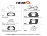
STEP 2
Measure wall thickness and cut zero clearance sleeve
parts to proper length (MAXIMUM 12”/305 mm). Assem-
ble sleeve and attach to firestop with #8 sheet metal
screws (supplied). Install firestop assembly. (Fig. 22)
Zero clearance sleeve is only required for
combustible walls.
ZCS101
Zero Clearance Sleeve
3/11/99 djt
Max. Length
12” (305mm)
#8 Screws (2)
#8 Screws
(2)
Adjustable
Zero Clearance
Sleeve
#8 Screws
(2)
Adjustable Zero Clearance Sleeve
ZCS101
Fig. 22 Adjustable zero clearance sleeve.
Firestop
STEP 3
Place fireplace into position. (Fig. 23) Measure the verti
-
cal height (X) required from the base of the flue collars
to the center of the wall opening.

16
RDV4136 Series Direct Vent Gas Fireplace
10010618
X
FP1240
Fig. 23 Vertical height requirement.
STEP 4
Attach the appropriate venting component(s) to the
inner and outer flue collars of the fireplace using three
(3) screws. (Fig. 24) Follow with the installation of the
inner and outer elbow. Again secure joints with three (3)
sheet metal screws.
STEP 5
Measure the horizontal length requirement including
a 2” (51 mm) overlap, ie from the elbow to the outside
wall face plus 2” (51 mm) (or the distance required if
installing a second 90° elbow). (Fig. 24)
Always install horizontal venting on a level
plane.
FP1243
Fig. 26 Apply high temperature sealant to collars or termina-
tions.
STEP 6
Use appropriate length of
pipe sections - telescopic
or fixed - and install the
horizontal vent sections.
The sections which go
through the wall are pack-
aged with the starter kit,
and can be cut to suit if
necessary. (Fig. 25)
Sealing vent
pipe and
firestop gaps
with high tem-
perature seal-
ant will restrict
cold air being
drawn in around
fireplace.
STEP 7
Guide the vent terminations 4” and 7” collars into their
respective vent pipes. Double check that the vent pipes
overlap the collars by 2” (51 mm). Secure the termina-
tion to the wall with screws provided and caulk around
the wall plate to weatherproof. (Fig. 26) As an alterna-
tive to screwing the termination directly to the wall you
may also use expanding plugs or an approved exterior
construction adhesive. You may also attach the termi-
nation with screws through the inner body into the 4”
(102 mm) vent pipe however for this method you must
extend the 4” (102 mm) pipe approximately 6” (152
mm) beyond the outer face of the wall.
X
FP1241
Fig. 24 Horizontal length requirement.
FP1242
Fig. 25 Through the wall.
Support horizontal pipes every 3’ (914 mm) with metal
pipe straps. Make sure the horizontal vent pipe is in-
stalled on a level horizontal plane.

17
RDV4136 Series Direct Vent Gas Fireplace
10010618
Vertical Sidewall Installation
Flex Vent Pipe
NOTE: The 40” (1016 mm) flex vent is used for 90° off
the top of the unit then out the back wall.
Follow Step 1 and 2 on Page 15.
Step 3
Install the four (4) spacer springs on the 4” flex vent
pipe. When installing the spacer springs around the 4”
pipe, stretch the spring to approximately 15” (381 mm),
wrap the spring around the pipe and interlock the ends
of the spacer spring approximately 2” (51 mm). Meas-
ure 6³⁄₄” (172 mm) from the end of the pipe. Place the
next spring 5” (127 mm) from the previously installed
spring. Place the next spring 6” (152 mm) from the last
spring. Finally place the last spring 12” (305 mm) from
the last spring installed. (Fig. 27)
12"
(305mm)
6"
(152mm)
5"
(127mm)
6"
(172mm)
FP1474
spacer springs
4/04 djt
4” Flex Vent
Pipe
Spacer Spring
FP1474
Fig. 27 Install spacer springs.
Step 4
Install the 4” (102 mm) flex vent pipe to the appliance
collar as described on Page 12. Secure the end with
the first spring 6³⁄₄” (172 mm) from the flex pipe end to
the unit.
Step 5
Slide the 7” (178 mm) flex vent pipe over the 4” flex
vent pipe and secure the 7” collar as described on Page
12.
Step 6
Bend the flex pipe horizontal so the bottom of the
horizontal pipe measure 18¹⁄₂” (470 mm) from the top
of the unit immediately after the 90° formation. (Fig. 28)
Be sure to follow the 1” (25 mm) rise in a 24” (610 mm)
horizontal run rule.
Step 7
Install the 4” flex then 7” flex to the termination.
FP1846
flex 90 bend
3/08 djt
6”
(165 mm)
FP1846
Fig. 28 Bend flex vent at 90° so horizontal portion is 6¹⁄₂”
(165 mm) off top of unit.
Below Grade Installations
When it is not possible to meet the required vent ter-
minal clearances of 12” (305 mm) above grade level a
snorkel vent kit is recommended. It allows installation
depth of down to 7” (178 mm) below grade level. The
7” is measured from the center of the horizontal vent
pipe as it penetrates through the wall.
If venting system is installed below
ground, we recommend a window well with
adequate and proper drainage.
Ensure sidewall venting clearances are observed.
If installing a snorkel a minimum 24” (610 mm) vertical
rise is necessary. The maximum horizontal run with
the 24” (610 mm) vertical pipe is 36” (914 mm). This
measurement is taken from the collar of the fireplace
(or transition elbow) to the face of the exterior wall.
Refer to the Sidewall Vent Graph for extended
horizontal run if the vertical rise exceeds 24” (610 mm).
1. Establish vent hole through the wall. (Fig. 21)
2. Remove soil to a depth of approximately 16” (406
mm) below base of snorkel. Install drain pipe. Install
window well (not supplied). Refill hole with 12” (305
mm) of coarse gravel leaving a clearance of approxi-
mately 4” (102 mm) below snorkel. (Fig. 29)
3. Install vent system.
4. Ensure a watertight seal is made around the vent
pipe coming through the wall.
5. Apply high temperature sealant caulking (supplied)
around the 4” and 7 “ snorkel collars.
6. Slide the snorkel into the vent pipes and secure to
the wall.
7. Level the soil to maintain a 4” (102 mm) clearance
below snorkel. (Fig. 29)
Do not back fill around snorkel. A clear-
ance of at least 4” (102 mm) must be main-
tained between snorkel and the soil.

18
RDV4136 Series Direct Vent Gas Fireplace
10010618
If the foundation is recessed, use recess brackets (not
supplied) for securing lower portion of the snorkel.
Fasten brackets to wall first, then secure to snorkel
with self drilling #8 x 1/2 sheet metal screws. It will be
necessary to extend vent pipes out as far as protruding
wall face. (Fig. 30)
BG402a
Top Vent
Below grade installation
1/26/00 djt
Firestop
7” Pipe
7TDVSNORK
(Snorkel)
4” (102mm)
Clearance
Min.
Window
Well
Gravel
Drain
BG402
Fig. 29 Below grade installation.
Zero Clearance
Sleeve
(if required)
*A minimum of 24” (610mm) ver
-
tical pipe must be installed when
using the 7TDVSNORK Kit.
*The 22” (559mm) vertical rise
(center to center) of the snorkel
may be included for calculationof
max. horizontal run.
24” (610mm)
Minimum*
Screws
Foundation Wall
Vertical Through-the-Roof Applications
This Gas Fireplace has been approved for:
• Vertical installations up to 40’ (12 m) in height. Up
to a 10’ (3 m) horizontal vent run can be installed
within the vent system using a maximum of two 90°
elbows. (Fig. 31)
BG401
Snorkel
2/10/99 djt
Snorkel
Wall Screws
Foundation Recess
Recess Brackets
Watertight Seal
Around Pipe
Sheet Metal
Screws
BG401
Fig. 30 Snorkel installation, recessed foundation.
Max. 10' (3m)
Max. Height
40' (12m)
Min. Height
7' (2.3m)
FP1244
through the roof
max/min dims
12/02
Pipe Straps Every
3’ (914mm)
FP1244
Fig. 31 Support straps for horizontal runs.
• Up to two 45° elbows may be used within the
horizontal run. For each 45° elbow used on the
horizontal level the maximum horizontal length must
be reduced by 18” (457 mm).
Example: Maximum horizontal length
0 x 45° elbows = 10’ (3 m)
1 x 45° elbows = 8¹⁄₂’ (2.6 m)
2 x 45° elbows = 7’ (2.1 m)
• A minimum of an 8’ (2.4 m) vertical rise.
• Two sets of 45° elbows offsets within these vertical
installations. From 0 to a maximum of 8’ (2.4 m) of
vent pipe can be used between elbows. (Fig. 32)
• 7DVCS must be used to support offsets. (Fig. 34)
This application will require that you first determine
the roof pitch and use the appropriate starter kit.
(Refer to Venting Components List)
• The minimum height of the vent above the highest
point of penetration through the roof is 2’ (610 mm).
(Fig. 36)
Vertical Through-the-Roof Installation
1. Locate your fireplace.
2. Plumb to center of the (4” (102 mm) flue collar from
ceiling above and mark position.
3. Cut opening equal to 9
³⁄₈” x 9³⁄₈” (240 x 240 mm).
4.
Proceed to plumb for additional openings through
the roof. In all cases, the opening must provide a
minimum of 1” (25 mm) clearance to the vent pipe,
i.e., the hole must be at least 9³⁄₈” x 9³⁄₈” (240 x 240
mm).

19
RDV4136 Series Direct Vent Gas Fireplace
10010618
1
2
3
4
Max. 8' (2.4m)
FP1245
through the roof
90 & 45 degree
12/02
1 + 2 + 3 + 4 = 270°
FP1245
Fig. 32 Typical offset application.
CFM100a
Firestop-Vertical
11"
(279mm)
11"
(279mm)
Attic Insulation
Shield
Joist
Ceiling In-
stallation
Joist
Upper Floor
Firestop Spacer
Nails (4)
CFM100a
Fig. 33 Place firestop spacer(s) and secure.
CFM110
Typical ceiling/roof support
10/90
Typical Roof Support
Application
Typical Ceiling Sup
-
port Application
CFM110
Fig. 34 Roof and ceiling supports.
TWL101a
Twist Lock Pipe
2/8/99 djt
#8 Sheet Metal Screws
(3 per joint)
Sealant
Storm Collar
TWL101a
Fig. 35 Roof flashing.
9. Install storm collar and seal around the pipe.
10. Add additional vent lengths for proper height. (Fig.
36)
Min.
2' (610 mm)
CFM190
TTR Ternim. 2'
1/25/02 sta
CFM190
Fig. 36 Minimum termination to roof clearance.
5. Place fireplace into position.
6. Place firestop(s) #7DVFS or Attic Insulation Shield
#7DVAIS into position and secure. (Fig. 33)
7. Install roof support (Fig. 34) and roof flashing making
sure upper flange of flashing is below the shingles.
(Fig. 35)
8. Install appropriate pipe sections until the venting is
above the flashing. (Fig. 35)
If there is a room above ceiling level,
firestop spacer must be installed on both
the bottom and the top side of the ceiling
joists. If an attic is above ceiling level a
7DVAIS (Attic Insulation Shield) must be
installed.
The enlarged ends of the vent section
always face downward. (Fig. 35)

20
RDV4136 Series Direct Vent Gas Fireplace
10010618
584E
Venting Components
Telescope vent
2/25/99 djt
10/20/99 twist lock
Venting Components
584G
Venting Components
Firestop spacer
2/25/99 djt
584H
Venting components
attic insulation shield
2/25/99 djt
584I
vent components
offset support
2/25/99 djt
584D
Vent Components
90 degree elbow
2/25/99 djt
10/20/99 twist lock
584C
Vent components
45 degree elbow
2/25/99 djt
10/20/99 twistlock
584F
Venting Components
Pipe sections
2/25/99 djt
10/20/99 twist lock
Starter Kit -
Model 7TDVSK - Sidewall Venting (Twist Lock Pipe)
Model 7FDVSK - Sidewall Venting (Flex Vent Pipe)
Models 7TDVTK/TV - Hot Touch Termination Kits
Model 7TDVTVTK/TV - Cool Touch Termination Kit
Starter Kit - Model 7TDVSKV - Vertical Venting
for 7TDVSKV-A order 1/12 to 6/12 roof pitch
for 7TDVSKV-B order 7/12 to 12/12 roof pitch
for 7TDVSKV-F order flat roof
Starter Kit for Below Grade Installation
Model 7TDVSKS -Snorkel Kit (Twist Lock Pipe)
Model 7FDVSKS -Snorkel Kit (Flex Vent Pipe)
Starter Pipe
Model 7TDVP 20/8 - 24” Starter Pipe Bulk
Model 7FDVP 30/8 - 30” Flex Pipe Bulk
45
o
Elbow
7TDV45 for Rear Vent to Vertical Vent
or Vertical/Horizontal Offsets
90
o
Transition Elbow
7TDVRT90 for Rear Vent to Vertical Vent
90° Elbow
7TDV90 Vertical/Horizontal Offset
Telescopic vent sections
7TDVP1117 -11” to 17” adjustable length
7TDVP3567 -35” to 67” adjustable length
Pipe sections for vertical or horizontal venting
Model 7TDVP8” - 4 per box
Model 7TDVP12” - 4 per box
Model 7TDVP24” - 4 per box
Model 7TDVP36”
Model 7TDVP48”
Firestop Spacer
Model 7DVFS
Attic Insulation Shield
Model 7DVAIS
Vertical/Horizontal Combination Offset Support
Model 7DVCS
584B
Vent components
Starter Kit
2/25/99 djt
/