WIA Weldmatic Fabricator Owner's manual
- Category
- Welding System
- Type
- Owner's manual
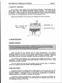
WIA Weldmatic Fabricator is a heavy-duty welding power source with constant voltage type. Suitable for welding applications ranging from sheet metal to heavy plate, and metals ranging from carbon steel to aluminum alloys, using shielding gases or self-shielded wires. The unit features a welding current range of 40 - 380 Amps, rated output of 270 Amps at 30 Volts, and a duty cycle of 100% at 270 Amps, 60% at 320 Amps. It comes with a wirefeeder, gun cable, regulator, and flowmeter, and can be connected to a 415V 3-phase 50Hz power supply.
WIA Weldmatic Fabricator is a heavy-duty welding power source with constant voltage type. Suitable for welding applications ranging from sheet metal to heavy plate, and metals ranging from carbon steel to aluminum alloys, using shielding gases or self-shielded wires. The unit features a welding current range of 40 - 380 Amps, rated output of 270 Amps at 30 Volts, and a duty cycle of 100% at 270 Amps, 60% at 320 Amps. It comes with a wirefeeder, gun cable, regulator, and flowmeter, and can be connected to a 415V 3-phase 50Hz power supply.


-
 1
1
-
 2
2
-
 3
3
-
 4
4
-
 5
5
-
 6
6
-
 7
7
-
 8
8
-
 9
9
-
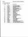 10
10
-
 11
11
-
 12
12
-
 13
13
-
 14
14


WIA Weldmatic Fabricator Owner's manual
- Category
- Welding System
- Type
- Owner's manual
WIA Weldmatic Fabricator is a heavy-duty welding power source with constant voltage type. Suitable for welding applications ranging from sheet metal to heavy plate, and metals ranging from carbon steel to aluminum alloys, using shielding gases or self-shielded wires. The unit features a welding current range of 40 - 380 Amps, rated output of 270 Amps at 30 Volts, and a duty cycle of 100% at 270 Amps, 60% at 320 Amps. It comes with a wirefeeder, gun cable, regulator, and flowmeter, and can be connected to a 415V 3-phase 50Hz power supply.
Ask a question and I''ll find the answer in the document
Finding information in a document is now easier with AI
Related papers
-
WIA Weldmatic 200 Owner's manual
-
-
-
-
-
-
-
-
-

