Page is loading ...

MFJ-9402 Instruction Manual 2 Meter SSB Transceiver
1
INTRODUCTION
Congratulations on your choice of the MFJ-9402. We think you'll enjoy countless hours
rag-chewing, chasing grids, contesting, and roving as you explore the fascinating world of
VHF weak-signal communication. Please read this manual thoroughly before attempting
to operate your unit. Here are some of the radio's features we think you'll like:
Easy to Operate: Just turn on and tune in! No microprocessor mumbo-jumbo to learn,
and no complex commands to memorize.
Potent Signal: Constant Current
syllabic speech processing gives your signal 4-6 dB
added punch to break pileups or climb above the noise.
Energy Efficient: All-analog circuitry uses minimal energy. Mountain top and rove on
portable power, or operate from home with a small 2-Amp regulated supply.
Sensitive Receiver: A low-noise front-end and doubly-balanced mixer fight intermod,
yet dig into band noise for weak signals. If the signal's there, you'll hear it!
Excellent Selectivity: Sharper selectivity does make a difference on VHF. Fight contest
QRM and enjoy reduced passband noise with HF-style 2.3 kHz ladder filter.
Real S-Meter: Full-sized electromechanical meter displays subtle changes. Aim your
beam with pin-point accuracy and give out signal reports that mean something!
Agile Tuning: Reduction-drive analog VFO lets you scan for signals quickly, then zero
in smoothly without sudden rate shifts or stair-stepping. Ideal for fast-paced hunt-and-
pounce operation during contests and band openings!
Amplifier Friendly: Built-in FET switch keys solid-state or tube amps. Output signal is
tailored for most popular multi-mode "brick" amplifiers (call 800-647-1800 for the latest
information on Mirage VHF-amplifier products).
Built to Last: Conservative design, premium FR-4 plate-through PC board, state-of-the-
art SMD layout, handsome brushed-aluminum panel, and tough vinyl-clad case make for
good looks and years of dependable service.
Optional MFJ-416 CW Module: Communicate with CW stations instantly--no need to
switch modes, sidebands, or to fiddle with the RIT. Just grab the key and start sending.
A must for snagging elusive grids, extra contest points, or auroral contacts!
At home or on the road, you'll enjoy superb two-meter performance with your MFJ-9402.
Best of all, it's fully backed by MFJ's exclusive NO MATTER WHAT
one-year
guarantee. If it breaks, we'll take care of it.

MFJ-9402 Instruction Manual 2 Meter SSB Transceiver
2
GENERAL DESCRIPTION
The MFJ-9402 is a compact and economical SSB transceiver designed especially for
fixed or portable communication in the weak-signal segment of the two-meter band.
Although normally configured for USB voice communication, the MFJ-9402 will also
operate on CW with the addition of the MFJ-416 semi-QSK CW-adapter module.
Energy-efficient analog circuitry conserves energy, while syllabic RF speech processing
ensures on-air performance equal to larger and more powerful radios. Other features
include a sharp HF-style crystal filter, built-in heavy-duty 3" speaker, analog mechanical
S-meter, "ergonomic" operating controls, and a built-in phone jack for walkman
style
stereo phones.
Typical Specifications
Receiver Section:
Frequency Coverage:..................................144.000-144.300 MHz
Receiver Type: ...........................................Single-conversion superhet
Frequency Control:..................................... Crystal-heterodyne VFO, low-side injection
IF Frequency:..............................................10 MHz
IF Selectivity:.............................................-6 dB @ 2.3 KHz
AGC: ..........................................................Audio-derived, 70-dB range
Sensitivity:..................................................MDS <.1 uV, S9 = 10 uV
AF Output:..................................................500 mW speaker, 100 mW phones
Average Rx Current: ..................................60-mA, (S-meter lamp disabled)
Transmitter Section:
RF Power Output:.......................................7 watts PEP into 50 ohms*
VSWR Tolerance: ...................................... 3:1 or greater
Peak Tx Current: ........................................1.5 Amps (13.8 vdc)
Speech Enhancement: ................................RF compression, syllabic rate
Spurious Attenuation:.................................-60 dBc or better
CW Generation:..........................................A1 carrier, adjustable offset**
Mic Input:................................................... 600-Ohm dynamic, PTT
* Note that most "10-watt input" multi-mode solid-state amplifiers are spec'd for FM service and require
significantly less than 10-watts for linear SSB operaton.
** The MFJ-416 CW adapter is required for CW operation ($39.95). Easy-to-install plug-in board
provides semi-QSK operation and built-in sidetone.

MFJ-9402 Instruction Manual 2 Meter SSB Transceiver
3
QUICK-START OPERATING INSTRUCTIONS
•
Power Supply: Use any well-regulated 13.8-V DC supply (1.5-amp or greater) or a
suitably-rated 14-V battery pack. The MFJ-9402 will also run on 12-volts at slightly
reduced RF output. Use a 5.5mm x 2.1 mm coaxial power plug with the + lead
attached to the center pin of the connector (use Radio Shack 274-1569).
•
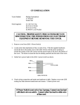
Microphone: The MFJ-290 handheld microphone was especially selected for MFJ-
9400-series radios, but virtually any 600-ohm dynamic mic will work if it has a 5-pin
DIN connector wired as shown below (use RadioShack 274-003).
1
4
2
5
3
Pin 3 = PTT Line
Pin 4 = Mic Line
Pin 1,2,5 = Ground
Mic
PTT
Gnd
Important Note
:
The PTT switch must cut both mic line and PTT line during receive.
Never use an amplified microphone--it will overdrive the speech processor.
•
Antenna: Use any horizontally polarized 2-meter antenna exhibiting a VSWR of 2:1
or less at 144.2 MHz. Avoid antennas with unknown or high VSWR. A simple dipole
or omni-directional halo may be adequate for local contacts, but a 5-10 element
directional yagi will yield vastly superior long-range performance and is strongly
recommended (see antenna tips on page 5).
•
Speech Processor: The MFJ-9402 features a built-in syllabic speech processor. For
best results, hold the mic about 1-inch from your lips and speak normally. Avoid
close-talking or yelling. The S-meter should deflect about 1/2-scale with normal
speech. A Mic Gain trimpot is located on the rear panel. The factory-default gain
setting is mid-range, or 12-o'clock.
•
External Power Amplifiers: The MFJ-9402 is especially designed to compliment
most popular 10-watt input 2-meter FM/SSB amplifiers. The Ext Amp jack provides
ground-closure on transmit to key the amplifier. Be sure to follow all amplifier
manufacturer's instructions closely and make any needed adjustments to avoid
exceeding your amplifier's safe drive level on SSB. In many cases, SSB drive
requirements will be significantly lower than those required for FM operation. See
amplifier primer and drive-level adjustment instructions on page 4.
•
Receiver Preamplifiers: If your external PA features a built-in GaAsFET preamp, try
using it. If you observe an audible improvement in signal-to-noise ratio on weak
signals and a desierable increase in overall sensitivity, you may wish to leave it in line.
However, if it makes the background noise dis-proportionately louder than weak

MFJ-9402 Instruction Manual 2 Meter SSB Transceiver
4
signals, leave it off. Also, note that extra preamplification may degrade the radio's
overload performance and IMD immunity when strong signals are near-by.
CONNECTING A MULTI-MODE AMP TO THE MFJ-9402
Mic Amp
Ext
Pwr
Antenna
Ext Keying
Radio
Antenna
Pwr
MFJ-9402
Two-wire Patch Cable
Coax
Drive Requirements: The "10-watt input" rating assigned VHF amps typically refers to
FM operation. As illustrated below, SSB drive requirements may be substantially less
because of the need to maintain amplifier linearity. Overdriving on SSB results in two
types of interference-generating non-linearity. First, gain compression causes amplifier
IMD performance to deteriorate rapidly, adding distortion to the audio and making your
signal needlessly broad. Second, saturation causes flat-topping, a condition that clips the
SSB waveform and produces sever splatter. On SSB, your amplifier should always be
driven at levels below the point where significant gain compression begins.
0
50
100
150
36
912
15
0
Operating
Region
Gain
RF
OUTPUT
(watts)
RF INPUT (watts)
SSB
FM/CW
Input/Output Power Curve for a "Typical" 150-W VHF Amplifier
Operating
Region
Saturation
Compression
Excessive
Drive
Gain
Setting Drive Level: As a rule-of-thumb, plan to run your VHF amp at .66 x full-rated
FM output power. For example, if your brick is rated for 150 watts on FM, run it at 100
watts PEP on SSB (.66 x 150 = 99). In most cases, this will keep your amp linear. The
MFJ-9402 is normally adjusted for 7-watts PEP output. While this is right for some
amps, it may overdrive others. If so, you may reduce drive by re-setting ALC trimpot
R73 for the desired level (R73 is located near the antenna connection on the left-rear
corner of the PC board--see Page-9 for trimpot locations). To monitor amplifier output,
connect a true peak-reading wattmeter between the amp and a low-VSWR 50-ohm load
(a good antenna will do). To generate a ALC-limited SSB signal, speak loudly into the
microphone so the processing meter deflects vigorously. Adjust R73 until your amplifier
delivers 66% of its full-rated FM output on the wattmeter. If you use an average-reading
wattmeter (Bird 43, etc), note that the meter movement will read a lot lower--only about
40-50% of the PEP value with syllabic processing (or 40-50 Watts for a 150-W amp).
Also, note that the transceiver's processor meter will read higher as you increase ALC

MFJ-9402 Instruction Manual 2 Meter SSB Transceiver
5
voltage and reduce power output. This is normal. Remember, if you overdrive your VHF
amp on SSB, the signal won't get any louder--but it's guaranteed to get a lot broader!
MFJ-9402 CONTROL LOCATION AND FUNCTION
MFJ TWO-METER SSB TRANSCEIVER
MODEL MFJ-9402
144.0
144.1
144.2
144.3
1
2
3
4
5
6
FINE
TUNE
8
VOLUME
ON
OFF
MIC
XMIT
KEY
7
FRONT PANEL
1. S-METER: Measures signal strength on receive, ALC on transmit
2. POWER: Applies power to the radio.
3. MIC: 5-pin DIN connector for PTT microphone.
4. XMIT LED: Illuminates when transmitter is keyed.
5. KEY: 3.5mm mono key jack--used with MFJ-416 CW adapter.
6. VFO TUNING: Tunes in stations, indicates operating frequency.
7. FINE TUNE: Fine tune control to assist with precise SSB tuning.
8. VOLUME: Adjusts listening level.
MFJ Enterprises, Inc
Starkville, MS USA
Mic Gain
Amp Phones Pwr
Antenna
1
3
4
2
5
REAR PANEL
1. MIC GAIN: Adjusts transmitter audio level (normal setting 12:00).
2. EXT AMP: Keys linear amplifiers--closure to ground on transmit.
3. PHONES: 3.5mm mini-jack wired for stereo headphones
4. POWER JACK: 5.5mm OD, 2.1mm ID, [+] to center pin.
5. ANTENNA: SO-239 for standard 50-Ohm coaxial plug.

MFJ-9402 Instruction Manual 2 Meter SSB Transceiver
6
TWO-METER ANTENNA SYSTEMS
While serious VHF DXers sometimes construct huge antenna systems, it's quite easy to
achieve outstanding results with only a modest installation. Here are some tips for
selecting antennas and getting top performance from your new VHF-SSB station:
•
Antenna Selection: Before purchasing your antenna, first survey the site where you
plan to install it. For a densely wooded area or location with nearby obstructions,
consider mounting a smaller light-weight antenna as high as possible to get above RF-
absorbing foliage and ground clutter. For open locations, a larger antenna (with more
gain) mounted at a lower height may yield better results. Also, assess your "hardware"
options. If you have a tower with a strong rotor available, a single long-boom antenna
is probably the best choice. However, if you are restricted to a roof-top installation
using TV hardware, a mid-size yagi--or a stacked array using two or more short-boom
yagis--may make more sense. When starting out, even a single 5 to 10-element yagi on
a good TV mast can yield very good results. Remember, VHF antenna systems are
easy to expand and upgrade over time, so there's no need to do everything at once!
•
Feedline Routing: For best performance, 2-meter yagis should be mounted as high
and in the clear as possible. However, at 144 MHz, it's also important to factor in
feedline loss. If you must add 50 additional feet of coax to gain only 10 feet in height,
it may not be worth the trouble! Take time to plan out and measure feedline runs
before making a final decision. Also, calculate your anticipated line loss using the data
from coax-loss charts. Feedline attenuation greater than 1-2 dB will begin to make a
discernible difference in your station's weak signal performance.
•
Coax Cable: RG8X foam coax may be sufficient for short direct cable runs (no more
than 50 feet). However, for longer runs, it really pays to install high-quality low-loss
cable such as 9913--or a more-flexible equivalent. Be sure to seal exterior connectors
against moisture with silicon compound or rubber tape--water incursion damages low-
loss cables very rapidly. To reduce loss, avoid installing unessential in-line devices
such as coax switches, barrel splices, and power meters. Also, use premium
connectors, install them carefully, and avoid sharp bends or kinks in the feedline.
•
Rotor: A light-duty TV rotor handles most small or mid-sized yagis, but long-boom
arrays require the extra torque and breaking action of a "ham" rotor.
•
Safety: Never install antennas where they can accidentally fall and contact power
lines or residential entrance cables. For electrical-hazard protection, permanently
ground the mast outside the building using a ground system with multiple rods. Also,
always disconnect the feedline from the radio at the first sign of threatening weather
(even nearby strikes may damage sensitive receiver circuitry). Finally, never install
antennas alone. Make sure someone knows where you are and what you are doing so
they can render assistance in the event of an unexpected problem or accident.

MFJ-9402 Instruction Manual 2 Meter SSB Transceiver
7
OPERATING ON TWO METER SSB
Unlike the HF amateur bands, there is relatively little atmospheric background noise on
2-meter SSB to cover up extremely weak signals. Because of this benefit, even modestly-
equipped stations can expect to communicate routinely over distances ranging from 75 to
150 miles without using repeaters or relying on band openings. Of course, when band
openings do occur, the communication range may increase significantly. Here are some
of the more common forms of 2-meter "skip":
Tropospheric Enhancement: Tropospheric bending, or "tropo", is the most common
form of "lift" at 144 MHz. Tropo occurs when warm air overrides entrenched cold air,
forming a thermal barrier aloft. Instead of passing into space, VHF radio waves duct
along this barrier, extending communication well beyond 100 miles--to as much as 1000
miles or more. Watch for signs of tropo on VHF-TV, FM Broadcast, or two-meter FM.
Auroral Enhancement: "Aurora" most often appears in the early evening hours around
the spring and fall equinox on days when the NBS K-index is over 4. Be sure to use CW
on 2-meters. Unlike at 6-meters, SSB becomes too "buzzy" and distorted copy on the
higher bands. Point your beam North and listen for DX up to 800 miles away.
Meteor Scatter: Random meteor bursts normally enhance distant signals for only a few
seconds. However, during a shower or storm, meteors may hit frequently enough to
support complete two-way exchanges of QSO information. This can yield fantastic DX.
Watch your favorite magazine's VHF column for predicted meteor shower dates.
Sporadic E: Look for "E-skip" during June-July, and again in November-December--
around the summer and winter solstice. E openings are much shorter and less frequent on
2-meters than on 6 and 10, but they are dramatic--yielding contacts of 1200 miles or
more.
EME: Earth-Moon-Earth propagation involves bouncing SSB or CW signals off the
moon to work world-wide DX. While you won't achieve 2-way "moon-bounce" with a 5-
element yagi and 10 watts, many have done it on CW using only a 160-Watt brick and a
single medium or long-boom yagi. Monitor the low edge of the band for EME activity
when the moon is full and low on the horizon. You might be pleasantly suprised by what
you'll hear--and work!
GRID SQUARES
On VHF SSB, the maidenhead world-wide grid locator system is used to identify
approximate station location (see the U.S. map provided at the back of this manual). A
typical QSO report might go, "You're 5-by-6 in Echo Mike 52". This means, "your Q5
signal is S-6 here in grid square EM52" (central Mississippi). VHF operators collect new
"grids" the same way HF hams collect states and countries. Most VHF contest scores and

MFJ-9402 Instruction Manual 2 Meter SSB Transceiver
8
awards are based upon the grid locator system. Know your grid--you'll be asked for it
often!
THEORY OF OPERATION
General: The MFJ-9402 is a 7-Watt USB voice transceiver covering 144.0-144.3 MHz.
CW operation may be added with the addition of the MFJ-416 plug-in CW adapter.
Receiver: Bandpass filter L1/L2 pre-selects incoming 144 MHz signals prior to pre-
amplification by Q1. U1 down-converts received signals to 10 MHz, where ladder filter
Y1-Y6 sets a 2.3 kHz USB message-channel bandwidth. IF amplifier U2 boosts and
levels the filtered SSB signal using audio-derived AGC. Product detector U3 self-injects
10-MHz LO and demodulates the USB signal, routing recovered audio to op-amp U4a for
amplification. U4a drives AGC amp Q3/Q4 and AF-power amp U5. Switch Q2 selects
between a slow AGC rate in receive mode and a fast (syllabic) ALC rate in transmit.
Transmitter: Mic-amp U4b and BFO U3 drive balanced modulator U7. DSB output is
routed to IF filter Y1-Y6, which strips the unwanted sideband and shapes audio response.
U2 then amplifies and levels the 10-MHz USB IF signal using RF-derived ALC.
Transmit mixer U8 combines IF and VFO signals, and the 144 MHz product is selected
by filter L9/10. RF amplifier Q10 boosts this signal prior to additional filtering at
L11/12. Driver MMIC Q11 boosts RF level to +5 dBm PEP for final amplification. PA
stage U11, a 2-stage linear RF-power module, delivers approximately 7-watts PEP on
SSB and 5-8 watts CW. Output is fed through a half-wave harmonic filter at L13/14 and
routed to T/R relay K1. During transmit, PTT switch Q9 drives T/R relay K1.
Mixing VFO: Mixer U6 combines an internally-generated 6-MHz VFO signal with 128-
MHz LO generated by crystal-oscillator/tripler Q6. The mixer's 134-MHz product is
selected at L6/L7 and fed to buffer Q7. The output of Q7 is filtered at L8 and level-
corrected for driving U1 and U8.
Regulation and Protection: Adjustable monolithic regulator U9 sets Vcc at 10.25 volts
for most of the radio's low-level stages. Regulator U10 supplies 5 Volts to the mixing
VFO, and U12 biases the PA module on during transmit. A crowbar at D10 protects
circuitry from accidental reverse-polarity damage.
Amplifier Keying: FET switch Q13 provides ground-path closure for keying an external
linear amplifier when the transceiver is in transmit mode.
MFJ-416 CW Adapter (optional): On initial key contact, RC-timed switching
establishes semi-QSK operation by activating the PTT line and re-biasing the radio's fine-
tune varactor for CW offset (offset is adjustable). To generate CW characters, additional
switching unbalances SSB modulator U7--forcing it to generate A1 carrier. Switching
also powers a built-in 2.8-kHz sounder to provide sidetone (internal sidetone may be
defeated when using a keyer with sidetone).

MFJ-9402 Instruction Manual 2 Meter SSB Transceiver
9
BLOCK DIAGRAM, MFJ-9402 TWO-METER SSB TRANSCEIVER
U1
REC
MXR
XTAL
FIL
U2
IF AMP
AGC
Y1-6
U3
PROD
DET
Q5
GATE
U4A
AF
PREAMP
VOL
U5
AUDIO
AMP
AGC/ALC
AMP
Q2,3,4
M
Q1
LNA
BPF
Q9
T/R
LPF
U7
BAL
MOD
Q8
GATE
U4B
MIC
AMP
Q7
BUF
U6
VFO
MXR
Q6
OSC
BPF
U11
PA
Q11
DRIVE
U8
TRANS
MXR
ANT
TUNE
VFT
U9
REG
10.5V
U10
REG
5V
Q13
EXT
SW
U12
BIAS
REG
X3
Q10
POST
AMP
BPF
BPF
MFJ-9402 Internal Adjustments: (see pictorial on page 9)
[1] Voltage Regulator: Adjust V-REG trimpot for 10.25V on tab of U9 [15].
[2] RSSI Threshold: Adjust AGC trimpot for 4.3 V at RSSI test point [13].
[3] Meter Zero: Adjust M-ZERO trimpot for zero meter reading w/o signal.
[4] IF Transformers: Peak IF cans T1,T2 for best receiver sensitivity.
[5] RF Transformers: Peak RF coils L1,L2 for best receiver sensitivity.
[6] BFO: Set BFO trimcap so skirt peak corresponds with 600-Hz beat note.*
[7] VFO Cal: Tune signal generator and VFO to 144.200 MHz, set L3 for zero beat.
[8] Mixing VFO: Peak L5,L6,L7,L8 for best receiver sensitivity.
[9] Carrier Balance: Set BAL trimpot for minimum carrier.
[10] Mic Gain: Set trimpot to preference--12-o'clock position is factory default.
[11] Transmitter Bandpass Filters: Install a shorting plug at [12] to insert carrier, and
turn ALC trimpot [14] clockwise to disable ALC line. The meter should not move on
TX. Key mic and peak L9,L10,L11,L12 for maximum output on a RF Wattmeter. After
aligning, remove shorting plug and restore ALC trimpot to previous setting.
[12] Carrier Insert: Shorting plug location to insert carrier for tuning driver trimpots.
[13] RSSI Test Point: Used when setting RSSI trimpot [2].
[14] ALC Level: Key mic and speak, adjust ALC trimpot for 1/2-scale meter deflection.
[15] V-REG Test Point: Set V-REG trimpot [1] for 10.25-V on regulator tab.
* Resetting BFO will change audio characteristics, also may unbalance carrier.
** If CAR BAL alone doesn't produce -40dBc null, interactively adjust BAL and T3.

MFJ-9402 Instruction Manual 2 Meter SSB Transceiver
10
PICTORIAL DIAGRAM -- INTERNAL ADJUSTMENT LOCATIONS
CARRIER
CARRIER
INSERT
L1
L2
T1
T2
T3
MIC GAIN
RSSI
V-REG
ZERO
PA OUTPUT
ALC
VFO CAL
VFT
VOL
VFO TUNE
KEY
TX
MIC
PWR
PWR
EXT AMP
1
2
3
4
5
6
7
9
10
11
12
14
13
BFO
TP
METER
VFO FIL
BAL MOD
RX IF
RX/TX IF
RX RF
LEVEL
BALANCE
15
PHONES
VFO LO
BANDPASS
VFO BUFF
BANDPASS
TP
8
IMPORTANT WARNING: The tune-up information provided in this
manual does not constitute a step-by-step guide for aligning
the MFJ-9402. If you lack the test equipment, experience, and
skills to align VHF SSB transceivers, do not attempt to make
these adjustments on your own! Far better to contact the MFJ
factory for assistance. Mis-alignment may cause permanent
damage to your unit or may result in interference to other
radio services in violation of FCC rules. MFJ cannot be held
responsible for the performance of radios that have been
improperly tampered with or mis-adjusted.
TECHNICAL ASSISTANCE
If you have any problem with this unit first check the appropriate section of this manual.
If the manual does not reference your problem or your problem is not solved by reading
the manual, you may call MFJ Technical Service at 601-323-0549 or the MFJ Factory at
601-323-5869. You will be best helped if you have your unit, manual and all information
on your station handy so you can answer any questions the technicians may ask.
You can also send questions by mail to MFJ Enterprises, Inc., 300 Industrial Park Road,
Starkville, MS 39759; by Facsimile (FAX) to 601-323-6551; or by email to
[email protected]. Send a complete description of your problem, an

MFJ-9402 Instruction Manual 2 Meter SSB Transceiver
11
explanation of exactly how you are using your unit, and a complete description of your
station.
TROUBLESHOOTING GUIDE
Radio does not power up: Check power plug, power lead, and power supply. Also,
check reverse-polarity protection fuse (etched on the pc board next to power jack J3).
If open, install a 3-A pig-tail fuse above the pc fuse using the holes at each end.
No signals received: Check antenna and feedline for breaks or shorts.
Spurious signals received: Look for interference from nearby computers, modems,
TVs, cordless phones, or other devices that may emit spurious 144-MHz signals.
Erratic transmit: Check antenna VSWR. Also, check battery or power supply
voltage. If supply drops below 12V under load, the radio's regulator will "drop out"
and operation will become erratic. If you operate from a 12-V battery, reduce the V-
REG trimpot for 10.0 Volts to ensure regulation (measure on U9 regulator tab).
High meter deflection on transmit, low RF output: ALC voltage may be set
incorrectly--or--the antenna impedance may be much higher than the specified 50
ohms. Check for a open feedline or for excessive VSWR. If okay, adjust R73 for
mid-scale deflection into a 50-ohm dummy load with normal speech.
Splatter, low meter deflection: ALC voltage (trimpot R73) may be incorrectly set--
or--antenna load impedance may be much lower than the specified 50 ohms. Look
for a shorted feedline or excessive VSWR. If okay, adjust R73 for mid-scale
deflection into a 50-ohm load with normal speech.
S-meter does not return to zero: Confirm V-REG (R78) is set for 10.25V on tab of
U9 and AGC threshold (R11) is set for 4.3V at RSSI test point (w/o signal). When
both voltage are set, adjust the Meter Zero trimpot (R17) for zero meter deflection.
Poor carrier suppression: Connect radio to a dummy load and turn the Mic Gain
trimpot (R52) fully off. Monitor your operating frequency with a two-meter receiver-
-a FM-HT or scanner will work for checking unmodulated carrier. Key the MFJ-9402
PTT switch carefully adjust Carrier Balance trimpot (R57) for minimum signal in the
monitor. If you cannot obtain a minimum of -40dBc suppression, detune T3 slightly
and re-try.
Low or distorted transmit audio: Check to see if the mic gain is set too low. Also,
make sure you are using a 600-Ohm low-Z dynamic microphone.
Excessive background noise or hum on signal: Mic gain may be set too high for
ambient noise conditions. Also, the dynamic mic element may be too close to a large

MFJ-9402 Instruction Manual 2 Meter SSB Transceiver
12
power supply transformer or electric motor. Move mic away and see if hum
disappears.
SCHEMATIC

MFJ-9402 Instruction Manual 2 Meter SSB Transceiver
13
U.S. GRID-LOCATOR MAP
/