Marley Engineered Products GV 16 User manual
- Type
- User manual
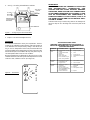
Marley Engineered Products GV 16 is a fully automatic gable mounted attic ventilator designed for general ventilating use only in the attic spaces of houses, apartments and other small buildings. Unit can be installed behind existing attic louvers to exhaust hot air or pull in cool air. An accessory dehumidistat can be used with this unit to automatically activate in the winter to help eliminate excessive moisture.
Marley Engineered Products GV 16 is a fully automatic gable mounted attic ventilator designed for general ventilating use only in the attic spaces of houses, apartments and other small buildings. Unit can be installed behind existing attic louvers to exhaust hot air or pull in cool air. An accessory dehumidistat can be used with this unit to automatically activate in the winter to help eliminate excessive moisture.


-
 1
1
-
 2
2
-
 3
3
-
 4
4


Marley Engineered Products GV 16 User manual
- Type
- User manual
Marley Engineered Products GV 16 is a fully automatic gable mounted attic ventilator designed for general ventilating use only in the attic spaces of houses, apartments and other small buildings. Unit can be installed behind existing attic louvers to exhaust hot air or pull in cool air. An accessory dehumidistat can be used with this unit to automatically activate in the winter to help eliminate excessive moisture.
Ask a question and I''ll find the answer in the document
Finding information in a document is now easier with AI
Related papers
Other documents
-
Construction Metals VER2 Installation guide
-
Marley Ceiling Fan Accessories User manual
-
iLIVING ILG8G14-12T User manual
-
Air Vent 84115 Operating instructions
-
Broan 35316 Installation guide
-
Broan 353 User manual
-
QuietCool GA ES-1500 Installation guide
-
-
 Air Vent WCGB Dimensions Guide
-
