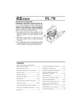
FLAT-TWIN FOUR STROKE ENGINE
Gemini
SERIES
OWNER'S
INSTRUCTION MANUAL
OSAKA-JAPAN

IMPORTANT: Before attempting to operate your engine, please read through these instructions
and separate sheet enclosed so as to familiarize yourself with the controls and other features of
the engine. Also, pay careful attention to the recommendations contained in the "Safety Instruc-
tions and Warnings" leaflet enclosed.
Your "Gemini Series" engine is a scale-type horizontally-opposed twin-cylinder overhead-valve
four-stroke-cycle engine. It is a more powerful development of the FT-120 Gemini introduced
in 1979 and further demonstrates O.S. pre-eminence in four-stroke engine manufacture, as first
established in 1976 with the introduction of the single-cylinder FS-60 and continued in the latest
O.S. single, twin and multi-cylinder models.
Like all O.S. motors, the "Gemini Series" engines are built to standards of skilled craftsmanship
that have been developed through sixty years of O.S. production history, a history that is not
only the longest in the model engine manufacturing world, but includes such milestones as
the world's first and only production model 'Wankel' rotary engine, the world's first quantity-
produced model four-stroke-cycle engine and the world's first model aircraft engine to be equip-
ped with a genuine supercharger.
Quality is a watchword at the O.S. factory, which is equipped to a standard unequalled by any
other manufacturer in the industry world-wide. Fully computerized modem machinery and the
use of carefully selected top quality materials ensure the production of engines of consistent
performance and long life.
-1-

Gemini SERIES
Right (No.2) cylinder
Rocker cover
Left (No.1) cylinder
Exhaust pipe
Safety propeller locknut assembly
Crankcase
Cylinder head
Carburettor
Push rod cover
(Photo shows FT-160) There are
small
differences in the appearance of the other Gemini
engines.
Photo.
1
-2-

NAMES OF ENGINE PARTS
Intake pipe (right)
Breather nipple
Intake manifold
Fuel inlet
Choke valve
Intake pipe
(left)
Rear housing
(Photo shows FT-160) There are small differences in the appearance of the other Gemini engines.
-3-
Photo. 2

INSTALLATION if the tank is located high, fuel will flow into the carburettor
"Gemini
Series"
engines
should
be
mounted
with
the
when the tank
is
full.
Therefore, pinch the fuel line
with
a
carburettor
below the crankcase, otherwise
scale
ap-
clip,
when the engine
is
not
running,
to
prevent
flooding
pearance may be spoiled, and loss of fuel.
The needle-valve and throttle lever locations are inter- FUEL
changeable and the choke valve rod can be located right or
left. Decide their most convenient locations before mount- The "Gemini Series" engine runs on standard commercially
ing the engine in the fuselage, available model glowplug engine fuel. Fuels containing
castor-oil and/or synthetic lubricants are acceptable but, for
FUEL
TANK
the best performance and
reliability,
a
fuel containing
5—15% nitromethane is recommended.
The ideal fuel tank location is with the top of the tank For consistent performance and long life of the engine, it is
5-10
mm
(1/4-3/8")
above
the
needle
valve.
However, advisable
to
use
good
quality
fuel
containing AT LEAST
model design will usually require the tank to be located 10% lubricant.
higher than this and there should be no trouble with such a
tank location provided that you do not pursue spectacular
acrobatic flight.
-4-

GLOWPLUG
With a
four-stroke engine, ignition of the fuel charge takes
place at every fourth stroke of the piston instead of every
two strokes. Because of this, conventional two-stroke glow-
plugs may not suit this engine in some cases. For general
use, the special O.S. Type F glowplug is recommended.
CHOKE VALVE
"Gemini Series" engines are equipped with a spring-loaded
choke valve. The choke valve operating lever can be located
right or left by reversing the hexagon nut and cap screw.
After mounting the engine in the model, secure the L-
shaped choke rod by tightening the set-screw. If the rod
supplied is too long, reduce it to the required length. If
the rod length is more than 40 mm (1-1/2 in.) its outer end
should be supported to avoid vibration.
Fig.1
Take care that the rubber pad does not become detached.
-5-

CARBURETTOR
The needle-valve and throttle lever locations are inter-
changeable by reversing the carburettor. This can be done
as follows:
Remove the carburettor carefully by unscrewing the two
screws which secure both carburettor and choke valve.
After reversing the carburettor, re-insert it into the intake
manifold, taking care not to damage the 0-ring in the
manifold.
Carburettor and choke-valve
fixing screws
Fig. 2
-6-

PROPELLER
The choice of propeller depends on the size and weight
of
the model and on the type of flying envisaged. Determine
the best size after practical experiment.
Suggested propellers are shown in the separate instructions
sheet. For safety, keep your face and other parts of the
body well away from the propeller when starting the engine
or when adjusting the needle-valve while the engine is run-
ning. Remember that the propeller turns through a much
wider arc with the larger sized propellers that this engine is
capable of driving.
Refer to the "Safety Instructions and Warnings" leaflet
enclosed.
IMPORTANT: Use well balanced propellers only. An
unbalanced propeller causes vibration and
loss of power.
The larger displacement O.S. engines were originally
designed so that the propeller could be fixed to the engine
with screws, as weil as the usual nut, in order to prevent
propeller slippage. However, if the propeller nut or screws
are inadequately tightened, this can (due to detonation or
"knocking" if the engine is run too lean or under too heavy
a load) cause the propeller to split and fly off. Obviously,
this can be very dangerous.
It is recommended, therefore, to use the Safety Propeller
Locknut Assembly supplied with the engine to prevent the
propeller from fracturing or flying off, even if it loosens.
(See Figs 3, 4 & 5)
Lockout spacer
Lockout
Propeller nut
Propeller washer
Propeller washer
Lock nut
Propeller nut
Drive hub
Propeller
Drive hub
Fig.
3
Back-plate of spinner
Fig. 4
Drive hub
Propeller washer pig. 5
Locknut
Propeller nut
-7-

Installation procedure is as follows:
1) Ream the propeller centre hole to the size indicated in
the separate instructions sheet. Make sure that the
propeller is properly balanced.
2) Fit the propeller sleeve-nut and washer to propeller,
screw onto shaft and tighten firmly with 17 mm wrench
supplied.
If the Safety Propeller Lockout Assembly of your engine
is supplied with the Locknut Spacer, add the Spacer if
the dimension "T" indicates you should do so, in the
separate instructions sheet.
3) Finally, insert the Safety Propeller Locknut. Tighten
Locknut firmly (but not with excessive force) using
14 mm wrench.
PROPELLER WASHER SET FOR SCALE MODEL
If you prefer to use the standard prop-nut and retaining
screws (see Fig. 6) to obtain more scale-like appearance
choose a propeller that has a boss at least as large as the
diameter of the drive hub so that it is not weakened when
drilied for the retaining screws. If the screws are not used,
the propeller may loosen (due to detonation when running
or preignition when starting) and, if the engine is running,
the propeller will fly off, complete with the retaining nut
and washer. This can be very dangerous.
Therefore, secure the prop nut and screws as follows:
1) Drill 3 mm diameter holes accurately through propeller
boss to exactly align with those in prop washer and drive
hub. Do not drill holes oversize.
2) Install prop, prop washer, screws and prop nut.
3) Tighten prop nut.
4) Tighten screws progressively and
evenly
in the
order
shown in the sketch.
5) Repeat steps 3) and 4) above to make sure that the prop
is really secure.
-8-

Regardless of the type of propeller fixing used, make a
habit of always checking the tightness of the propeller
before starting the engine. Remember that, especially with
wooden propellers, there is a tendency for the material to
shrink, or for it to be reduced by the serrated face of the
drive hub.
When removing the propeller from the engine between
flying sessions, it is recommended to withdraw it complete
with drive hub, instead of removing the six retaining
screws. Be careful not to lose the Woodruff key at this
time.
(One spare Woodruff key is supplied with the engine.)
NEEDLE-VALVE AND FUEL INLET
The needle-valve supplied with this engine is designed to
incorporate an extension so that, when the engine is en-
closed within the fuselage, the needle-valve may be adjusted
from the outside. An L-shaped rod, of 1.6-1.8 mm dia.
and appropriate length, should be inserted into the needle's
centre hole and secured by tightening the set-screw in the
needle-valve knob with the small Alien key provided. For
longer extension, it is recommended to use a piece of flexi-
ble control cable, together with the knob and support hook
supplied. Also, the fuel inlet nipple on the carburettor can
be adjusted to the most suitable position for connecting to
the fuel delivery tube from the tank. Slacken the needle-
valve
holder
with
the 8 mm wrench provided, reset
the
inlet
nipple at the required angle and re-tighten.
GLOWPLUG WIRING
A set of glowplug leads, with clips, is supplied with the
engine. The lug plate of the earth lead should be fastened
to the motor mount by means of one of the engine fixing
screws.
Observe the following precautions:
1) Make sure that no part of the wire or glowplug clip
touches the cylinder head or cooling fins.
2) Keep wiring away from the fuel tank, where it might
cause a fire in the event of a short-circuit.
Battery Capacity
It is advisable to use a glowplug battery of fairly large
capacity (e.g. 20 AH in the case of a rechargeable lead-
acid cell) as this is required to heat two glowplugs simul-
taneously.
-9-

Battery Leads
As the battery leads are required to conduct a large current
(approx. 6 amps), make sure that the wire used is heavy
enough to prevent excessive voltage-drop at the plugs.
Note: It is inadvisable to use a variable resistance or rheostat as, in
the event of one plug lead becoming accidentally detached
(or the plug element failing) excessive voltage will be applied
to the other plug. The alternative is to use a separate battery
and rheostat for each plug.
STARTING
It is preferable to use an electric starter, although hand-
starting is also possible, as will be explained in a moment.
When applying the starter, be sure to connect both glow-
plugs to the battery.
(It is possible to start the engine on
one cylinder only, then
to connect the other glowplug to the battery to run the
engine on both cylinders, but this is not advisable since it
causes needlessly unequal loading of the engine initially.)
1) Open the throttle fully and unscrew the needle-valve
3-1/2 turns from the fully closed position.
2) It is preferable to use the choke control for priming.
3) Close the choke valve and turn the propeller counter-
clockwise 2 turns by hand keeping the throttle valve
fully open.
4)
Release the choke control and immediately turn the
propeller counter-clockwise several times so that fuel is
drawn well into the cylinders.
5)
Set
the
throttle
valve
approximately
1/3
open
from
the
fully closed position. Connect the glowplugs to the
battery and apply the electric starter.
6) When the engine starts, open the throttle valve fully and
keep it running, initially (approx. 10 seconds), with the
original needle-valve setting. If the engine slows down
because the mixture is excessively rich, close the needle-
valve
slowly approx.
1/4
—
1/2
turn.
7) Now disconnect the battery from the glowplugs and
close the needle-valve slowly so that revolutions are
increased. Adjust the needle-valve gradually. Abrupt
adjustment of the needle-valve may cause the engine to
stop, especially when it is new and insufficiently run-in.
8) To re-start the engine when warm, simply re-energise the
plugs and reapply the starter with the throttle in the
idling position. If the engine does not restart, re-prime
by closing the choke valve while rotating the propeller
twice with the throttle open. Initially, the high tempera-
ture inside the combustion chambers may turn the liquid
fuel into gas and emit it through the exhaust pipes.
Therefore, repeat the priming procedure once or twice
until the cylinders become cool enough for restarting.
CAUTION:
Never
apply
an
electric
starter
with
the
choke closed.
Such action will cause an excessive quantity of fuel
to be drawn into the cylinder and result in an
hydraulic lock that may damage the engine. Do not
turn the propeller more than 2 turns, initially, with
choke closed, otherwise the engine
may suck in too
much fuel and become flooded.
CAUTION: Do not connect the glowplugs to the battery when
priming. The adjustment of the needle-valve should
be done only after disconnecting the battery from
the glowplugs.
-10-

Hand Starting
For safety be sure to use a heavily padded glove or 'chicken-
stick'. The procedure is as follows:
1) The propeller should be fixed in such a way that it is
positioned horizontally as compression is first felt when
turning the propeller counter-clockwise.
2) Open the throttle valve fully and unscrew the needle-
valve 3-V2 turns from fully closed position.
3) Close the choke valve and turn the propeller counter-
clockwise through two revolutions.
4)
Release
the choke
valve
and
immediately
turn
the pro-
peller counter-clockwise several times
so as
to draw fuel
well into the cylinders.
5) Set the throttle at approximately 1/3 open from the
fully-closed position and gradually turn the propeller
counter-clockwise until compression is felt.
6) Connect the glowplugs to the battery and swing the
propeller smartly counter-clockwise from the centre of
the right blade. The engine should start. If it stops
again, make sure that fuel is reaching the carburettor
from the fuel tank, then repeat procedures 3) to 6).
Correct priming is the secret of easy starting.
7) When the engine starts, open the throttle fully and keep
it running, initially (approx. 10 seconds), with the
original needle-valve setting. If it slows down because
the mixture is excessively rich, close the needle-valve
about
1
/4
—
1/2
turn .
8) Now disconnect the battery from the glowplugs and
close the needle-valve slowly so that revolutions increase.
Adjust the needle-valve gradually. Abrupt adjustment of
the needle-valve may cause the engine to stop, especially
when it is new and insufficiently run-in.
9) To re-start the engine when it is warm, after a run, first
try just flipping the prop with the throttle in the idling
position after re-energising the glowplugs. If the engine
does not restart, re-prime it by closing the choke valve
while rotating the propeller twice with the throttle open.
Initially, high temperature inside the combustion
chambers may
turn the liquid fuel into gas and emit it
through the exhaust pipes. Therefore, repeat the
priming procedure once or twice until the cylinders
become cool
enough for restarting.
CAUTION: Do not connect the-glowplugs to the battery when
priming.
Note:
Excess
fuel
in the
carburettor
may
drip
into
the engine
compartment when the choke valve is reopened. There-
fore, it is advisable to drill a drain hole in the bottom of
the engine bay or cowling and to apply fuelproof paint to
the surrounding surfaces to prevent fuel from penetrating
the airframe structure.
-11-

RUNNING-IN ("Breaking-in")
For long life and peak performance,
please observe the
following running-in procedure:
Install the engine and fit the propeller that you propose to
use for flying your model. For example, if you use the pro-
peller indicated in the separate instructions sheet, start the
engine and run it for about 10 seconds with the needle-
valve
set
for
6,000/6,500
r.p.m.,
then open the
needle-
valve to reduce speed to approximately 4,000 r.p.m. and
run for 20 seconds at this cooler setting. Keep the throttle
fully open, using only the needle-valve to reduce speed.
Repeat this procedure, alternately running the engine fast
and slow with the needle-valve, but gradually extending the
short period of high
speed
running
until
a
total
of approxi-
matelylO minutes running time has been accumulated. For
those who do not have a tachometer, the exhaust gas
colour can be a help: i.e., as the needle-valve is screwed in,
the
dense
grey
exhaust smoke
will
become
less
visible.
Following the initial break-in of 10 minutes on the ground,
run-in for a further period in the air. For the first flights,
have the needle-valve set as rich as possible, consistent with
adequate take-off power and, if necessary, readjust the
throttle trim on the transmitter so that the engine does not
stop when the throttle is fully closed.
With
each
successive
flight,
close
the
needle-valve
slightly,
until,
at the end of 10 flights, the
needle-valve
is
set
for
maximum power. The carburettor can now be adjusted for
optimum throttle performance following the advice given in
the separate instructions sheet.
VALVE CLEARANCE ADJUSTMENT
Refer to the INSTRUCTIONS FOR USE OF VALVE
ADJUSTING TOOL KIT sheet contained in the Valve
Adjusting Tool Kit supplied with the engine.
EXHAUST PIPE ADJUSTMENT
The direction of the exhaust pipe may be altered in ac-
cordance with individual installation requirements. The
angle is easily adjusted by loosening the nut that secures the
exhaust pipe to the cylinder head. Use the appropriate
spanner supplied. If longer exhaust pipes are required
for the "Super-Gemini" 240/300 models, use the flexible
exhaust pipes of 12 cm, 17 cm, 24 cm or 33 cm length
which are available as optional extra parts.
LUBRICATION
All the parts of your engine are automatically lubricated by
the oil content of the fuel mixture. The crankcase breather
hole
is
in the
bottom
of the
timing
case
and
is
fitted
with
a
brass nipple. Fit a length of silicone tubing of approx.
2.5 — 3 mm I.D. to this nipple to conduct away the small
amount of oil that escapes through the breather, (see photo
2).
CARE OF YOUR "GEMINI SERIES" ENGINE
Your engine should be treated with the utmost care at all
times.
-12-

At the conclusion of a flying session, do not leave the
engine "wet" with raw fuel by stopping it after rich-mix-
ture running or prolonged idling. Instead, let it run for a
few moments at
full
throttle
with
the correct
needle-valve
setting, to bring it up to normal running temperature, then
cut off the fuel supply — preferably by removing the fuel
line from the carburettor. Extra protection against internal
corrosion should be given by injecting some special mois-
ture-displacing oil or light machine oil through the crankcase
breather and rotating the crankshaft for several revolutions
to draw the oil into the crankcase, etc.
Keep the engine in a clean, dry atmosphere when it is not in
use.
When the propeller is removed, replace it with the spacer
supplied and tighten the prop nut lightly. This will protect
the engine from internal damage in the event of an ac-
cidenta! blow to the crankshaft.
Do not dismantle the engine needlessly.
-13-

MEMO
-14-

© Copyright 2000 by O.S.Engines Mfg. Co., Ltd. All rights reserved. Printed in Japan.
O.S.ENGINES
MFG.CO.LTD
6-15 3-Chome Imagawa Higashisumiyoshi-ku
Osaka 546-0003, Japan TEL. (06) 6702-0225
FAX. (06) 6704-2722
URL: http://www.os-engines.co.jp
040100

INSTRUCTIONS FOB O.S. FT-160 (GEMINI-160)
TWIN-CYLINDER FOUR STROKE ENGINE
IMPORTANT: Before attempting to operate your engine,
please read through this instruction sheet, as well as the
GEMINI SERIES Owner's Instruction Manual supplied, so
as to familiarize yourself with the controls and other fea-
tures of the engine. Also, pay careful attention to the
recommendations contained in the "Safety Instructions and
Warnings" leaflet also enclosed.
The O.S. FT-160 (Gemini-160) is a horizontally-opposed
twin-cylinder overhead-valve four-stroke-cycle engine of
26.5cc (1.62cu.in) displacement. It has the same external
dimensions and appearance as the FT-120-11 (Gemini-11)
but, whereas the Gemini-11 is restricted to 19.9cc (1.21
cu.in) to bring it within the 20cc displacement limit for
FAI Class F4C R/C Scale events, the Gemini-160 takes
advantage of slightly bigger cylinders, providing more
power for non-restricted events, or for sport flying.
Like the Gemini-ll, the Gemini-160 is a very refined engine.
The horizontally-opposed layout, typical of modern light
aircraft engine design, provides very smooth running
qualities and docile, trouble-free handling characteristics.
Production of the Gemini-160 and the Gemini-ll —as with
their big brothers, the 40cc Super-Gemini and the 49cc
Super-Gemini-300 — was preceded by an exhaustive pro-
gramme of research and prototype testing. These engines
are, needless to say, built to the outstandingly high engi-
neering standards for which O.S. engines are famous word-
wide.
SPECIFICATIONS
Displacement
Bore
Stroke
Practical R.P.M.
Weight
13.26c.c.X2(0.809cu.in.X2)
27.7mm (1.091 in.)
22.0mm (0.866in.)
2.000-10.000
1,100gr. (38.8oz.)
TOOLS AND ACCESSORIES
The following tools and accessories are supplied with your
Gemini 160.
.
1. Radial Motor Mount Set:
Radial Motor Mount
..................
1
Mount Fixing
Screws
(M5
x
25)
............
4
Lock
Washers
(05)
....................
4
Blind
Nuts (M5)
......................
4
Engine
Fixing
Screws (M4
x
22)
............
4
2. Set
of leads for wiring glowplugs
Leads
for glowplug with clip
..............
2
Lead for earth (ground)
.................
1
3. Valve Adjusting Tool Kit
0.04mm...............................
1
0.10 mm ......................... . . 1
Hexagonal
(Alien) key
(1.5
mm)
..........
1
Wrench (5
mm)
..................... . . 1
4.
Needle-valve
extension
cable
............... 1
5. Knob for needle-valve extension (with set-screw) .. 1
6.
Hook for
needle-valve
extension
............. 1
7.
Choke
valve
rod
......................1
8.
Woodruff
key
(spare)
...................1
9. Scale Propeller Washer Set
Propeller
washer
....................
1
Propeller nut ....................... 1
Screws to prevent propeller slippage (M3 x 32) ... 4
10.
Hexagonal (Alien) key
(2.0
mm)
............
1
11.
Hexagonal (Alien) key
(2.5mm)
............
1
12.
Hexagonal
(Allen)
key
(3.0mm)
............
1
13.
Wrench
(5-6
mm)
.....................
1
14.
Wrench
(7-8
mm)
.....................
1
15.
Wrench
(10-12
mm)
....................
1
16.
Wrench
(14-17
mm)
....................
1
FUEL TANK
The suggested fuel tank size is 400 cc or 14 oz. This will
give approximately 10 minutes running time at full power,
or about 13-15 minutes when some part-throttle operation
is included. Fuel consumption also depends, of course, on
the size of propeller used.
PROPELLER
The choice of propeller depends on the weight of the model
and on the type of flying envisaged. Determine the best size
and type after practical experiment. As starting points, sug-
gested propel lers are 15 X 8, 16 X 6-8, 18 X 6-8 and 20 X 6.
If the Safety Propeller Locknut Assembly is used, instal-
lation procedure is as follows.
1) Ream the propeller center hole to 12 mm (0.472").
Make sure that the propeller is properly balanced.
2) Fit the propeller sleeve-nut and washer to propeller,
screw onto shaft and tighten firmly with 17 mm wrench
supplied.
Please refer to 'PROPELLER' section of GEMINI
SERIES Owner's Instruction Manual. If the dimension
"T" is between 14.5 mm and 18 mm (or 0.571" and
0.709"), add locknut spacer supplied as shown in Fig. 4.
If the dimension "T" is between 18 mm and 22-5 mm
(or 0.709" and 0.886"), it is not necessary to add the
spacer.
3) Finally, insert the Safety Propeller Locknut. Tighten
Locknut firmly (but not with excessive force) using
14 mm wrench.
CARBURETTOR ADJUSTMENT
The carburettor of your Gemini 160 has been factory set
for the approximate best result, but the setting may. in
some cases, vary slightly in accordance with fuel and cli-
matic conditions.
Remember, also, that, while the engine is being run-in and
the needle-valve is set on the rich side, the carburettor can-
not be expected to show its best response. Therefore, it is
recommended that you first run the engine with the throttle
settings as received. If, however, the desired throttle res-
ponse is not obtained after the completion of the running-
in period, the carburettor should be re-adjusted as follows.
Note:
Idling speed adjustments should be carried out with the fuel
tank not more than half-full and with the battery disconnected
from the glowplugs.

1) Start the engine, with the throttle 1/3 open from the
fully closed position, then open the throttle fully and
gradually close the needle-valve until the engine is run-
ning at its maximum speed.
CAUTION:
Do
not
close
the needle-valve
to
too
"lean"
a
setting
as
this
will
cause
the engine
to
overheat and slow
down.
Set
the
needle-valve
very
slightly
to
the
"rich"
side
of
the
peak
r.p.m.
setting.
Make
sure
that
the
engine
is
fully "broken-in" (about 1 hour of total running time
in short runs) before operating it continuously at full
throttle.
2) Now, close the throttle gradually. The engine should idle
continuously and steadily. If it does not. adjust as
follows.
a) If the engine begins to idle unevenly, first re-open the
throttle. If the engine hesitates before picking up to
full speed, it is probable that the idling mixture is too
rich. Check this by closing the throttle again and let-
ting the engine idle for a little longer before again
opening up. If the engine now puffs out a good deal
of smoke and hesitates or even stops, it will be neces-
sary to screw out the air-bleed screw to weaken the
mixture. Do this by turning it counter-clockwise.
About 1/2-1 turn should be sufficient.
b) If, instead of being too rich, the air-bleed screw is set
too lean, the engine will stop when the throttle is
closed, or will lose speed while idling and then cut-
out abruptly (without smoking) when the throttle is
opened again. In this case, turn the air-bleed screw
about 1/2-1 turn clockwise.
3) When the mixture, has been corrected, the idling speed
will probably increase. Re-adjust the throttle opening by
means of the throttle trim on the transmitter or by
screwing-out the throttle-stop screw so that the lowest
possible idling speed, without stopping the engine, may
be obtained.
4) It is recommended to. repeat procedure 2) several times
until the best result is obtained.
Subsequent Operation and Care
Once the required carburettor settings have been establish-
ed, it should be unnecessary to alter them. Such slight
needle-valve alterations as may be needed to cope with dif-
ferences in atmospheric conditions or fuels, do not affect
the other two adjustments.
It is important that the carburettor operates under clean
conditions. Make sure that the fuel is properly filtered
before use. We advise fitting a filter in your fuel can and
another in the delivery tube between tank and engine, to
reduce the risk of the carburettor jet becoming partially
clogged and upsetting running adjustments.
Remember to clean the filters occasionally.
PARTS LIST
Code No.
46101000
46101800
46102000
46103100
45903200
46103300
45403400
46104020
46104110
46104200
46105000
45906000
46108000
45508200
46120000
46110100
46013002
46114000
26731002
22130004
46030008
46031005
22631019
46160000
Description
Crankcase
Rear Housing
Crankshaft
Cylinder Liner
Piston
Cylinder Jacket
Piston Ring
Cylinder Head (w/valve assy)
Cylinder Head
Rocker Cover
Connecting Rod Assembly
Piston Pin
Drive Washer
Woodruff Key
Thrust Washer
Propeller Locknut Set
Screw Set
Head Gasket Set
Crankshaft Bearing (front)
Crankshaft Bearing (intermediate)
Crankshaft Bearing (rear)
Camshaft Bearing (front)
Camshaft Bearing (rear)
Valve Assembly (1 pc.)
Code No.
45361000
45961400
46162000
45564000
46166000
45566100
46168000
46168500
46168100
46168200
46169000
45471000
46109400
46181000
46184000
71615009
72200060
72200040
46130000
72200080
71910000
*46110200
*72403050
Description
Rocker Arm Assembly (1 pc.)
Rocker Support Assembly
Camshaft
Cam Follower (2 pcs.)
Push Rod (2 pcs.)
Push Rod Cover Set (2 pcs.)
Intake Manifold
Manifold Seal (2 pcs.)
Intake Pipe (right)
Intake Pipe (left)
Exhaust Pipe (1 pc.)
Breather Nipple (w/gasket)
Propeller Spacer
Carburettor Complete
Choke Valve Assembly
Glow Plug Type F
Valve Adjusting Tool Kit
Booster Cable Set
Scale Propeller Washer Set
Needle-valve Extension Cable
Radial Motor Mount Set
5/16-M5(L) Propeller Lockout Set
Super Filter (large)
* Optional Parts The specifications are subject to alteration for improvement without notice.
O.S.ENGINES
MFG.CO.,LTD
6-15 3-chome Imagawa Higashisumiyoshi-ku
Osaka 546, Japan. TEL. (06) 702-0225
FAX.
(06)
704-2722
Copyright 1990 by O.S. Engines Mfg. Co., Ltd. All rights reserved. Printed in Japan
/