Page is loading ...

BRB 5885
M A G N E T I C
RECUMBENT
BIKE
OWNER’S MANUAL
* This item is for consumer use only and it is not meant for commercial use.

WARNING: SERIOUS INJURIES AND EVEN DEATH CAN OCCUR IF THE PROPER SAFETY PRECAUTIONS ARE NOT FOLLOWED.
The diagram below highlights and reviews many of the important Safety and Warning labels also found
on the unit. Please ensure any user of the unit familiarizes themselves with these Safety and Warning
guidelines before use.
PLEASE KEEP THESE INSTRUCTIONS FOR FUTURE USE & REFERENCE.
DO NOT DISCARD.
The use of this exercise equipment involves a RISK OF PHYSICAL INJURY as well as
property damage, which can be minimized by observing the following guidelines:
1. ALWAYS wear comfortable clothing
and shoes with good traction.
2. ALWAYS make sure all nuts and bolts
are secured before use. TIGHTEN
PEDAL HINGE BOLTS EVERY 30
DAYS.
3. STOP EXERCISING if you be
come
dizzy, nauseous, have irregular
heartbeats or breathing difficulties.
Contact your physician immediately.
4. ALWAYS keep a large mat under the
Equipment to protect the floor or carpet.
5. ALWAYS use your Equipment in a
warm, dry, level well-lit and ventilated
indoor area.
7. ALWAYS keep your Equipment clean
and free
of dust, moisture, debris and
loose objects.
8. NEVER use the Equipment if you are
injured or have a physical condition
that impairs your balance. DO NOT
exercise under the influence of
medication or alcohol.
9. NEVER allow small children or pets to
approach the Equipment. It is not a
toy.
10. NEVER use the Equipment if you
exceed its weight limit of 250 lbs.
11. NEVER use the Equipment if it does
not function properly.
6. ALWAYS keep body and clothing free
and clear of all moving parts.
Page 1
BRB 5885
W A R N I N G !
!
Model No.:BRB5885
Distributed by:
HUPA INTERNATIONAL INC.
21717 Ferrero Parkway
Walnut, CA 91789 USA
(888) 266-6789
Date of Manufacture: month.year
This product is intended for
consumer use (non-institutional)
ONLY.

General Information
Safety
Before you undertake any exercise program,
please be sure to consult with your doctor.
Frequent strenuous exercise should be
approved by your doctor and proper use
of your product is essential. Excessive or incorrect
training may result to health injuries. Please read
this manual carefully before commencing the
assembly of your product or starting to exercise.
• Please keep all children away from this item
when in use. Do not allow children to climb or
play on them when they are not in use.
• Supervise teenagers while they use this unit.
• For your own safety, always ensure that there
is at least 3 feet of free space in all directions
around your product while you are exercising.
• Regularly check to see that all nuts, bolts and
fittings are securely tightened. Periodically
check all moving parts for obvious signs of
wear or damage.
• Clean only with a damp cloth, do not use
solvent cleaners. If you are in any doubt, do
not use your product; contact CUSTOMER
SUPPORT.
• Before use, always ensure that your product
is positioned on a solid, flat surface. If
necessary, use a rubber mat underneath to
reduce the possibility of slipping.
•
Always wear appropriate clothing and
footwear such as training shoes when
exercising. Do not wear loose clothing that
could become caught in moving parts during
exercise.
• Do not use this unit if it is not functioning
properly or if it is not fully assembled.
• Do not use this unit for commercial purposes.
This unit is for home use only.
Storage and Use
Your product is intended for use in clean
dry conditions. You should avoid storage in
excessively cold or damp places as this may
lead to corrosion and other related problems.
Weight Limit
Your product is suitable for users weighing:
250 pounds or less.
• Before use, you must read and understand all
instructions & warnings stated in this Owner’s
Manual as well as posted on the equipment.
• It is the facility owner’s responsibility to properly
instruct users on the proper operation of the
equipment and to warn them of the potential
hazards.
• If at any time during exercise you feel faint, dizzy
or experience pain, stop and consult your
physician.
Assembling Tools
- Ruler with both metric and English measurements
- 2 x Adjustable Wrenches
- 1 x Philips (”Crosshead”) Screw Driver
•
Any adjustment devices that could interfere with
the user's movement on this unit should not be
left projecting.
Page 2
BRB 5885
Warranty
HUPA International Inc. warrants your product
for a period of 1 year for the frame and 90 days
on all parts if the item is used for the intended
purpose, properly maintained and not used
commercially. Any alterations or incorrect
assembly of the product will void this warranty.
Proof of purchase must be presented for any
warranty validation (no exceptions). This
warranty applies to the original purchaser only
and is not transferable.
This warranty does not cover abuse or defects
caused during use, storage or assembly.
During the warranty period, HUPA International
Inc. reserves the right to:
a). provide replacement parts to the
purchaser in an effort to repair the item.
b). repair the product returned to our
warehouse (at the purchaser’s cost).
c). replace the product if neither of the two
previously mentioned actions effect repair.
This warranty does not cover normal wear and
tear on upholstery.
Questions
If you have any questions concerning the
assembly of your item or if any parts are
missing, please DO NOT RETURN THE
ITEM TO THE STORE OR CONTACT THE
RETAILER. Our dedicated customer service
staff can help you with any questions you may
have regarding the assembly of this unit and
can also mail you replacement parts.
Customer Support
Customer Support is open 9:00 a.m. to 5:00
p.m. (Pacific Time) Monday through Friday.
Please contact us by any of the following
means.
HUPA International Inc.
21717 Ferrero Parkway, Walnut, CA 91789
Telephone: (888) 266 - 6789
Fax: (909) 598 - 6707
Email: [email protected]

Hardware & Tool List
The following hardware is used to assemble your unit. Please take a moment to familiarize yourself with these
items. Please note some of this hardware is already pre-assembled on the machine. Do not be alarmed if you
see parts on this page that are not included in your hardware packet.
Bolt
Others & Tools
Washer
#02. Screw (M4x10 mm)
[4 pieces]
Pre-assembled
#07. Bolt (M8x16 mm)
[22 pieces]
Pre-assembled
#50. Carriage Bolt (M8x47 mm)
[2 pieces]
#53. Screw (M4x8 mm)
[2 pieces]
Pre-assembled
#21. Cap Nut (M8)
[6 pieces] Pre-assembled [4 pieces]
Nut
#08. Spring Washer (M8)
[24 pieces]
Pre-assembled [22 pieces]
#09. Arc Washer (M8)
[12 pieces]
#23. Washer (M8)
[20 pieces]
Pre-assembled [18 pieces]
Page 3
BRB 5885
#54. Washer (M4)
[6 pieces]
Pre-assembled
Pre-assembled
#38. Spring Loaded Knob
(M16x30 mm)
[1 piece]
#59. Tool 1
[1 piece]
#60. Tool 2
[1 piece]
#18. Carriage Bolt (M8x75 mm)
[4 pieces]
Pre-assembled
#61. Bolt (M8x20 mm)
[4 pieces]
Pre-assembled

Parts Listing
The following parts list describes all of the parts illustrated on the
exploded diagram on the following page. Please note, most of
these parts are already pre-assembled on your unit.
Page 4
BRB 5885
01 Monitor 30 Wire Plug
02 Screw (M4x10 mm) 31 R
ear Stabilizer
03 Round End Cap (Φ25x16 mm) 32 End Cap for Rear Stabilizer
04L L
eft Handle Bar 34 R
ectangular End Cap (40x80 mm)
04R Right Handle Bar 35 H
orizontal Bar
05
Foam Grip (Φ23x3x140 mm)
36 Bolt (M8x50 mm)
06
Foam Grip (Φ23x3x180 mm)
37 Washer (M8)
07 Bolt (M8x16 mm) 3
8 Spring Loaded Knob (M16x30 mm)
08 Spring Washer (M8) 39 Sleeve (50x100 mm)
0
9 Arc Washer (M8) 40 Sliding Block
10 Front Post 41 Screw (ST3x6 mm)
11 Handle Pulse Wire 1 42 Cushion Frame
12 Monitor Wire 1 43 Rectangular End Cap (25x50 mm)
1
3 Monitor Wire 2 44 Rear Handle Bar
1
4 Handle Pulse Wire 2 45 Hand Pulse
15 End Cap for Front Stabilizer 46 Screw (ST4.0x19 mm)
1
6 Front Stabilizer 47 Foam Grip (Φ23x3x560 mm)
1
7 Screw (ST3x10 mm) 4
8 Hand Pulse Wire 4
18 Carriage Bolt (M8x75 mm) 4
9 Reinforcement Plate
19 Main Frame 50 Carriage Bolt (M8x47 mm)
2
0L Left Pedal 51 Seat Cushion
20R
Right Pedal 52 Backrest Cushion
21 Cap Nut (M8) 53 Screw (M4x8 mm)
22L 54 Washer (M4)
23 Washer (M8)
55 Water Bottle Holder
24 Knob
Bolt (Φ32x21 mm)
56 Adapter
25 Handle Pulse Wire 3
57 Bumper
26 Bottom Frame
58 Washer (M4)
27L Left Small Shroud
59 Tool 1
27R
Right Small Shroud
60 Tool 2
28 Screw (ST4.2x19 mm)
29 Screw (ST4.2x16
mm)
22R
Left Cra
nk
Right Crank
61 Bolt (M8x20 mm)

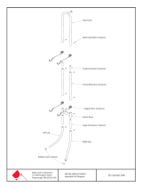
Exploded Diagram
The following diagram is provided to help you familiarize yourself with the parts and
hardware that will be used during the assembly process. Please note that not all of the
parts and hardware you see here will be used while you are assembling the machine
because some of these items are already pre-installed. Please continue to the next
page to begin the assembly process and use this page only as a reference guide for
parts and hardware.
Page 5
BRB 5885
01
51
52
07
23
43
45
45
03
03
47
47
44
41
41
40
39
39
41
34
35
34
20R
53
54
55
06
07
08
09
09
08
07
02
15
15
18
17
18
17
16
28
29
29
27R
26
25
27L
31
32
32
18
30
09
08
21
21
08
09
28
29
29
56
07
08
23
23
08
07
09
08
21
20L
07
08
23
13
14
11
12
09
08
07
07
10
05
06
05
04R
04L
43
61
08
23
24
03
03
03
21
08
23
46
46
49
50
48
30
36
08
37
08
37
36
38
42
09
08
07
19
41
07
23
57
58
28
57
58
28
03
59
60
22L
22R
33
54

A.) Front Stabilizer Assembly
Page 6
BRB 5885
NOTE: The Front Stabilizer has end
caps with built-in wheels
for easy storage and placement.
B
FRONT
Make sure these two wires are accessible and exposed (as shown)
before proceeding to the next step. If they have fallen
inside the tube, use a bent wire to “fish” them out.
20R
18
18
09
08
20L
21
16
19
22R
22L
Turn
COUNTER-clockwise.
Turn
clockwise
LEFT SIDE
RIGHT SIDE
A
A s s e m b l y S t e p 1
Attach the Front Stabilizer (#16) to the Main Frame (#19)
using two Carriage Bolts (#18), and secure with two Arc
Washers (#09), two Spring Washers (#08) and two Cap
Nuts (#21)
H a r d w a r e R e q u i r e d
B.) Pedal Assembly
Screw on the Right Pedal (#20R) to the Right Crank (#22R) by
turning the Right Pedal clockwise.
Repeat on the other side using Left Pedal (#20L) and turning
the Left Pedal COUNTER-clockwise.
Remove the pre-assembled parts from the Front Stabilizer
(#16) and set them aside nearby: two Carriage Bolts (#18),
two Arc Washers (#09), two Spring Washers (#08) and two
Cap Nuts (#21)
Bolt
Washer
#21. Cap Nut (M8)
[2 pieces]
Nut
#08. Spring Washer (M8)
[2 pieces]
#09. Arc Washer (M8)
[2 pieces]
#18. Carriage Bolt (M8x75 mm)
[2 pieces]
Assembly Instructions

A s s e m b l y S t e p 2
H a r d w a r e R e q u i r e d
B.) Bottom Frame Assembly
Remove these pre-assembled parts from the Bottom Frame
(#26) and set them aside nearby: six Bolts (#07) , six Spring
Washers (#08) and six Washers (#23).
With the help of an assistant, attach the Main Frame (#19) to the
Bottom Frame (#26) secure by using six Bolts (#07), six Spring
Washers (#08) and six Washers (#23).
Make sure this wire is
exposed and accesible
before assembling the
Main Frame (#19).
40
35
26
25
31
18
09
08
21
21
08
09
07
08
23
23
08
07
07
08
23
14
14
25
19
38
REAR
A.) Rear Stabilizer Assembly
Height Adjustable
End Caps
Connect Handle Pusle Wire 2 (#14) to the Handle Pusle Wire
3 (#25) as illustrated below (diagram D).
.
B
A
Page 7
BRB 5885
D
C.) Bottom Frame Assembly
Attach the Spring Loading Knob (#38) to the Sliding Block (#40).
C
Spring Loaded Knob Operation
Turn knob counter-clockwise three times.
Pull knob outward and adjust seat simultane-
ously
Push knob back inward until it clicks and then
tighten it by turning clockwise.
Attach the Rear Stabilizer (#31) to the Bottom Frame (#26)
using two Carriage Bolts (#18), and secure with two Arc
Washers (#09), two Spring Washers (#08) and two Cap
Nuts (#21)
Remove the pre-assembled parts from the Rear Stabilizer
(#31) and set them aside nearby: two Carriage Bolts (#18),
two Arc Washers (#09), two Spring Washers (#08) and two
Cap Nuts (#21)
Bolt
Others & Tools
Washer
#07. Bolt (M8x16 mm)
[6 pieces]
#21. Cap Nut (M8)
[2 pieces]
Nut
#08. Spring Washer (M8)
[8 pieces]
#09. Arc Washer (M8)
[2 pieces]
#23. Washer (M8)
[6 pieces]
#38. Spring Loaded Knob
(M16x30 mm)
[1 piece]
#18. Carriage Bolt (M8x75 mm)
[2 pieces]
Assembly Instructions

Assembly Instructions
A s s e m b l y S t e p 3
H a r d w a r e R e q u i r e d
A.) Cushion Frame Assembly
Page 8
BRB 5885
Remove the pre-assembled parts from the Sliding Block (#40)
and set them aside nearby: four Bolts (#61), four Spring
Washers (#08) and four Washers (#23).
B.) Rear Handle Bar Assembly
61
08
23
21
08
23
42
40
42
With the help of an assistant attach the Cushion Frame (#42)
onto the Sliding Block (#40), secure by using four Bolts (#61),
four Spring Washers (#08) and four Washers (#23).
Using the illustration below for reference, align the six holes of
the Reinforcement Plate (#49 ), Rear Handle Bar (#44) to the
holes on the Cushion Frame (#42) and secure using two Carriage
Bolts (#50), two Washers (#23), two Spring Washers (#08) and
two Cap Nuts (#21).
Connect the Hand Pulse Wire 3 (#25) to the Hand Pulse Wire
4 (#48) as illustrated below (diagram C).
A
Bolt
Washer
#61. Bolt (M8x20 mm)
[4 pieces]
#50. Carriage Bolt (M8x47 mm)
[2 pieces]
#21. Cap Nut (M8)
[2 pieces]
Nut
#08. Spring Washer (M8)
[6 pieces]
#23. Washer (M8)
[6 pieces]
49
44
25
48
48
25
50
B
C

A s s e m b l y S t e p 4
H a r d w a r e R e q u i r e d
A.) Cushion Assembley
Attach the Seat Cushion (#51) to the horizontal portion of the
Cushion Frame (#42) and secure using four Bolts (#07) through
four Washers (#23).
Page 9
BRB 5885
07
23
07
23
51
52
42
53
54
55
11
09
08
07
07
09
08
07
14
19
10
B
C
D
12
11
13
14
13
12
Remove the pre-assembled parts from the Front Post (#10) and
set them aside nearby: two Screws (#53) and two Washers (#54).
Attach the Water Bottle Holder (#55) to the Front Post (#10) and
secure using two Screws (#53) and two Washers (#54).
Remove the pre-assembled parts from the Seat Cushion (#51)
and set them aside nearby: four Bolts (#07) and four Washers
(#23).
Attach the Backrest Cushion (#52) to the vertical portion of the
Cushion Frame (#42) and secure using four Bolts (#07) through
four Washers (#23).
Remove the pre-assembled parts from the Backrest Cushion
(#52) and set them aside nearby: four Bolts (#07) and four
Washers (#23).
B.) Front Post Assembly
Being Carefully not to pinch any wires, slide the Front Post (#10)
onto the Main Frame (#19) and secure using four Bolts (#07) ,
four Spring Washers (#08) and four Acr Washers (09).
Connect the Hand Pulse Wire 1 (#11) to the Hand Pulse Wire 2
(#14), Connect the Monitor Wire 1 (#12) to the Monitor Wire 2
(#13) as illustrated below (diagram D).
C.) Water Bottle Holder Assembly
Remove the pre-assembled parts from the Main Frame (#19)
and set them aside nearby: four Bolts (#07) , four Spring
Washers (#08) and four Arc Washers (09).
A
Bolt
Washer
#07. Bolt (M8x16 mm)
[12 pieces]
#53. Screw (M4x8 mm)
[2 pieces]
#08. Spring Washer (M8)
[4 pieces]
#09. Arc Washer (M8)
[4 pieces]
#23. Washer (M8)
[8 pieces]
#54. Washer (M4)
[2 pieces]
Assembly Instructions

Assembly Instructions
H a r d w a r e R e q u i r e d
B
A
C
01
02
07
08
09
09
08
07
11
12
01a
01b
01a
01b
12
11
10
04R
04L
54
Using the illustration below for reference, align the four holes of
the Left Handle Bar (#04L) to the holes on the Front Post (#10)
and secure by using two Bolts (#07), two Spring Washers (#08)
and two Arc Washers (#09).
Repeat this process on the other side using Right Handle Bar
(#04R).
B.) Handle Bar Assembly
Remove the pre-assembled parts from the Front Post (#10)
and set them aside nearby: four Bolts (#07), four Spring
Washers (#08) and four Arc Washers (#09).
pre-assembled on the back of the Monitor (#01) , and set them
aside nearby.
Washers (#54)..
A s s e m b l y S t e p 5
Page 10
BRB 5885
After complete assembly: If the computer
is not picking up your hand pulse signal
(or you are getting
inaccurate readings), Please refer t
o our “Troubleshooting”
section on Page 19 for other troubleshoot
issues.
HAND PULSE SIGNAL
Troubleshooting
Remove the four Screws (#02) and four Washers (#54) that are
Connect the Hand Pulse Wire 1 (#11) to the wire on the back of
the Monitor (#01). Connect the Monitor Wire 1 (#12) to the wire
on the back of the Monitor (#01) as illustrated below(diagram C).
Then slide the Monitor (#01) onto the bracket of the Front Post
(#10). Secure them together by using four Screws (#02) and four
A.) Monitor Assembly
Bolt
Washer
#02. Screw (M4x10 mm)
[4 pieces]
#07. Bolt (M8x16 mm)
[4 pieces]
#08. Spring Washer (M8)
[4 pieces]
#09. Arc Washer (M8)
[4 pieces]
#54. Washer (M4)
[4 pieces]

A s s e m b l y S t e p 6
Page 11
BRB 5885
The assembly process is now complete. However, for your own safety, please make sure to read this entire Owner’s Manual
which includes safety instructions and warnings, as well as any safety/warning labels affixed to the product before use.
For your safety, please visually and functionally inspect and test the unit after assembly is complete.
A). Adapter Assembly
Plug in the Adapter (#56) male plug into the female socket located at the front end of the unit.
56
19
Monitor
Warnning: This device complies with Part 15 of the FCC Rules. Operation is subject to the following two conditions:
(1) This device may not cause harmful interference.
(2) this device must accept any interference received, including interference that may cause undesired operation.
Caution:
This equipment has been tested and found to comply with the limits for a Class B digital device, pursuant to part
15 of the FCC Rules. These limits are designed to provide reasonable protection against harmful interference in a
residential installation. This equipment generates, uses and can radiate radio frequency energy and, if not installed
and used in accordance with the instructions, may cause harmful interference to radio communications. However,
there is no guarantee that interference will not occur in a particular installation. If this equipment does cause harmful
interference to radio or television reception, which can be determined by turning the equipment off and on, the user
is encouraged to try to correct the interference by one or more of the following measures:- Reorient or relocate the
receiving antenna.- Increase the separation between the equipment and receiver.- Connect the equipment into an
outlet on a circuit different from that to which the receiver is connected.- Consult the dealer or an experienced
radio/TV technician for help.
Assembly Instructions

• Make sure all nuts, bolts, and screws are tightened prior to use.
• Be sure that all adjustment locking devices and safety devices are properly engaged prior to use!
• Never over-tighten the above-mentioned devices and parts to avoid damage to the unit.
• Check for loose parts and components and make proper adjustments prior to use.
• Check to see if there are any tears or bends in the welding or metal prior to use. If tears or bends are found,
do NOT use the unit and contact our CUSTOMER SUPPORT.
• Extreme care must be taken to not allow your feet, fingers, hair, clothing, and/or any loose items to be snagged
into any portion of the bike when the unit is in motion
. Failure to follow these instructions could result in serious
injury, including the loss of fingers.
• Always wait for the pedals and other moving parts (which can gain great momentum during riding) to come to a
complete stop before dismounting the unit to avoid serious injury.
• Do not use solvent cleaners. If in any doubt, do not
use your cleansing product; contact CU
STOMER SUPPORT
MAINTENANCE & CARE
• For any replacement warning labels, please contact our CUSTOMER SUPPORT at (888) 266-6789 or
(909) 598-9876, or mail in a written request to: HUPA International Inc. 21717 Ferrero Parkway, Walnut, CA 91789.
More detailed information abou
t how to reach our CUSTOMER SUPPORT may be found on Page 2 of the Owner’s
Manual under the “CUSTOMER SUPPORT” section.
• The specific Parts on your unit which may see possible signs of wear after prolonged use are listed as follows
(please check these parts before each use):
Spring Loaded Knob (#38); Left Right Pedal (#20L/20R);
Backrest Cushion (#52) and Seat Cushion (#51).
• Please review all safety instructions and warnings in t
his entire Owner’s Manual, as well as any safety/warning
labels affixed to the product before use.
HOW TO (EMERGENCY) STOP
SAFETY & WARNINGS
NOTE: Always wait for the pedals and/or any other moving parts (which can gain great momentum during riding)
to come to a complete stop before dismounting the unit to avoid serious injury.
1. To reduce speed on the bike, you may use the combinations of your feet on the Left/Right Pedals (#20L/20R)
and your hands on either set of the front or rear handlebars (Front Handle Bar (#04L/04R) or Rear Handle Bar
2. Wait for the pedals to come to a complete stop.
3. Now you may safely dismount the unit
NOTE: To safely move, transport, and/or store the unit, please seek the help of capable assistants (minimum 2
(#44)) to gently and safely apply counter-momentum.
HOW TO MOVE/TRANSPORT THE BIKE FOR STORAGE
people total).The unit has integrated End Cap for Front Stabilizer (#15) purposely intended to help ease this
process.
1. Position one person on each side at the rear of the bike toward the Seat (one person on the left, and one
on the right).
2. Have each person use both hands to grip the corresponding Foam Grip (#47) for Rear Handle Bar near the
Cushion Frame (#42). (These are the safest areas to avoid injury during this process.)
3. Have both people simultaneously lift the rear end of the unit, leaving the weight and pressure into the front
of the unit and onto the End Cap for Front Stabilizer (#15) to move/transport the unit to the desired area.
Safety & Maintenance
Page 12
BRB 5885

Computer Operation
Page 13
BRB 5885
HOW TO START YOUR WORKOUT (2 OPTIONS):
A. "QUICKSTART" OPTION:
1.
To begin working out without having to go through any computer set-up.
Press ST/SP and be
your workout metrics.
2. Use "UP"/"DOWN" to adjust
resistance intensity during workout.
B. "PROGRAM SELECTION" OPTION:
(Manual / P1. Rolling / P2. Valley / P3. Fatburn / P4. Ramp / P5. Mountain / P6.Interval / P7. Cardio /
To select from a selec
on of workout programs
P8. Endurance / P9. Slope / P10. Rally /
Control / Heart Rate Control (55%, 75%, 95%, Target H.R.) /
User Se
ng)
1. Follow the instruc
ons in the following pages in this "Computer Opera on" sec on.
2.
Begin exercising.
The computer will automa ally start measuring and display your workout metrics by "Count-
Down" (if you preset any target values).

Computer Operation
"COUNT-UP" / "COUNT-DOWN"
Your computer is able to either "Count-Up" or "Count-Down" your workout metrics.
• When the computer is "Count-Up" measuring, it will automa
ally show your workout metrics increasing (i.e.
coun
ng up) from 0.
• When the computer is "Count-Down" measuring, it is because you have preset a target value for one or more of
the workout metrics: TIME / DISTANCE / CAL / PULSE and it will show your progress from your preset target
value decreasing toward 0 (i.e. coun ng down) when you reach/achieve your preset target value.
"COUNT-UP" / "COUNT-DOWN"
COMPUTER FUNCTIONS:
WORKOUT
PROGRAMS
(Manual Program (1); Preset Programs (10); Wa Control Program (1);
Heart Rate Control Programs (4); User Se
ng Programs (5)) = Total of 21 programs
SPEED Current speed displayed (in MPH)
RPM Current rota ons per minute
TIME When
Count-Up
: Accumulated exercise me for current workout session (in minutes/seconds) is
displayed
When Count-Down: Time will count down from the preset target value you selected to 0
DIST. When Count-Up: Accumulated distance for current workout session (in miles) is displayed
When Count-Down: Distance will count down from the preset target value you selected to 0
CAL
When Count-Up: Accumulated calories burned for current workout session is displayed
When Count-Down: Calories will count down from the preset target value you selected to 0
WATT Current w age output of user during exercise
PULSE Current user heart rate value in BPM (beats per minute)*
LEVEL Computer will display bar matrix to show levels and intensity (16 levels available)
AUTO SHUT OFF Computer will turn off automa ally if unit is not engaged in movement a er 4 min.
AUTO TURN ON Computer will turn on automa ally if movement on the unit is detected, or any bu n is pressed.
RESISTANCE
LEVELS
The computer display uses a bar-matrix grid which shows columns up to 8 rectangular increments.
ADAPTOR INPUT: AC 100-240V~ 50/60Hz 0.5A
OUTPUT: DC 9V 1A
* Please be aware that the pulse sensors are not medical devices; the pulse sensors should not be used or applied
for medical reasons.
***IMPORTANT*** Please remember that the func
ons in this computer are only meant to be tools to monitor your
workout progress; they are not meant to provide medical informa
on or be used for medical purposes. Please consult
a physician before beginning any workout program.
COMPUTER FUNCTIONS:
Page 14
BRB 5885

Computer Operation
GENERAL COMPUTER OPERATION ("HOW-TO"):
1. Ensure that your unit is plugged-in to an electrical source. Press a key and/or pedal to power on the computer.
2. Use UP and DOWN to select your desired workout program. Then press ENTER.
3. Se ng Workout Func ons
The computer allows you to preset certain func
ons. In other words, you can preset* your own workout target
goals for func
ons TIME / DISTANCE / CALORIES / WATT / TARGET HEART RATE.
*NOTES: 1. Some func
ons are not adjustable in certain programs; the computer should automa cally skip over
any func
ons in such cases. 2. When you preset any func ons, the display will countd
own from your value. Once
"0" is reached, the computer will beep to signal you have reached/completed your goal.
Once a program has been selected:
A. Press ENTER so that TIME func
on flashes.
B. Use UP or DOWN to set desired
me value.
C. Press ENTER to confirm the value. The flashing prompt will move to the next func
on.
D. Con
nue use of UP or DOWN to preset func ons as desired.
E. Press START/
STOP to begin workout.
4. The 21 workout func ons can be categorized under 7 basic workout "programs" which will be detailed:
(Manual Program (1 op
on); Preset Programs (10 op ons); Wa Control Program (1 op on);
Heart Rate Control Programs (4 op
ons); User Se ng Programs (5 op ons))
***IMPORTANT*** Please remember that the programs in this computer are only meant to be tools to monitor
your workout progress; they are not meant to provide medical informa
on or be used for medical purposes. Please
consult a physician before beginning any workout program.
BUTTON FUNCTIONS:
ENTER
• To enter/select desired program
• To confirm/set desired value or workout
programs
• To select display of Speed, RPM, or
alterna
ng display
ST./SP.
• Start and/or pause workout sessions
• Holding bu
on for 2 seconds will RESET all
func on values to be zero
UP
• Scroll up through workout programs
• Increases value of selected workout func
on
• During the workout, it will increase the
resistance level
DOWN
• Scroll down through workout programs
• Decreases value of selected workout
func
on
• During the workout, it will decrease the
resistance level
RECOVERY
• (A
er computer is already
reading/displaying your heart rate value) --
Press to enter into pulse recovery tes
ng
• Exit pulse recovery mode
Page 15
BRB 5885

Computer Operation
MANUAL / PRESET WORKOUT Programs
The
Manual Program
allows you to manually adjust the resistance levels throughout your workout session and
preset certain workout metrics. The Preset Workout Programs are pre-programmed rounes that simulate different
physical acvies or allow you to set specified target goals.
(Manual / P1. Rolling / P2. Valley / P3. Fatburn / P4. Ramp / P5. Mountain / P6.Interval / P7. Cardio /
P8. Endurance / P9. Slope / P10. Rally )
How to Set Funcons:
1. Use UP/DOWN to select the desired program.
2. Press ENTER to confirm.
3. If desired, you can preset values for funcons of Time/Distance/Calories, or, skip through any pre-seng
funcons by pressing ENTER.
a. To set values, use UP/DOWN to increase/decrease values.
b. Press ENTER to confirm desired values.
4.
Press START/STOP to begin workout session.
WATT CONTROL Programs
The Wa Program will automacally adjust resistance levels based on your input WATT value. The WATT value is
decided by the torque and RPM (rotaons per minute). In this program seng, the WATT value will keep at the
constant value which you preset. It means that if you peddle quickly, the resistance level will decrease, and, if you
peddle slowly, the load resistance will increase to ensure you maintain the preset wa value.
How to Set Funcons:
1. Use UP/DOWN to select the desired WATT program
2. Press ENTER to confirm.
3. If desired, you can preset values for funcons of Time/Distance/Calories, or, skip through any pre-seng
funcons by pressing ENTER.
a. To set values, use UP/DOWN to increase/decrease values.
b. Press ENTER to confirm desired values.
4. Use UP/DOWN to set desired waage amount*. The default is 100.
5. Press ENTER to confirm.
6. Press START/STOP to begin exercise.
Page 16
BRB 5885

Computer Operation
HEART RATE CONTROL Programs (55%, 75%, 95%)
The HRC Program will automacally adjust resistance levels based on your input PULSE value. In this program
seng, the PULSE value will keep at the constant value which you preselect. It means that if your heart rate starts
to increase, the resistance levels will decrease, and, if your heart rate starts to decrease, the load resistance will
increase to ensure you maintain the preselected PULSE value.
How to Set Funcons:
1. Use UP/DOWN to select the desired HEART RATE CONTROL program
2. Press ENTER to confirm.
3. If desired, you can preset desired values for funcons of Time/Distance/Calories/Age, or, skip through
any pre-seng funcons by pressing ENTER.
a. To set values, use UP/DOWN to increase/decrease values.
b. Press ENTER to confirm desired values.
4. Based on the user's inpued AGE, the computer will display the target heart rate in upper right corner.
5. Press START/
STOP to begin workout session.
HEART RATE CONTROL Program (TARGET HEART RATE)
The HRC (Target Heart Rate) Program will automacally adjust resistance levels based on your input PULSE value.
In this program seng, the PULSE value will keep at the constant value which you enter. It means that if your heart
rate starts to increase, the resistance levels will decrease, and, if your heart rate starts to decrease, the load
resistance will increase to ensure you maintain the entered PULSE value.
How to Set Funcons:
1. Use UP/DOWN to select the desired program
2. Press ENTER to confirm.
3. If desired, you can set desired values for funcons of Time/Distance/Calories, or, skip through any pre-
seng funcons by pressing ENTER.
a. To set values, use UP/DOWN to increase/decrease values.
b. Press ENTER to confirm desired values.
4. Use UP/DOWN to input the desired TGT HEART RATE.
5. Press ENTER to confirm.
6. Press START/STOP to begin workout session.
Page 17
BRB 5885

Computer Operation
USER PROFILE Programs
The User Program allows you to create your own program by adjusng each segment of the resistance levels. The
created program can also be saved for future workout sessions.
How to Set Funcons:
1. Use UP/DOWN to select the desired USER profile program.
2. Press ENTER to confirm.
3. If desired, you can set desired values for funcons of Time/Distance/Calories*, or, skip through any pre-
seng funcons by pressing ENTER.
a. To set values, use UP/DOWN to increase/decrease values.
b. Press ENTER to confirm desired values.
4. The first resistance level column will flash; press
UP/DOWN to set desired resistance intensity.
5. Press ENTER to confirm. Repeat process to set resistance for columns 2 to 10. The computer will store
the customized program.
6.
Press START/STOP to begin workout session.
RECOVERY Reading
NOTE: The pulse RECOVERY test compares your heart rate before and a exercise. It provides a reading that
gauges your body's overall ability to come back to a res ng state a er exercise ac vity.
How to Get a RECOVERY Reading:
The pulse RECOVERY test compares your heart rate before and a er exercise. It provides a reading that gauges
your body's overall ability to come back to a res
ng state a er exercise ac vity.
1. Place both hands gently on pulse sensors. Computer will start to read your pulse.
2. Whenever you are ready for your RECOVERY reading, press RECOVERY, and 1 minute (60 seconds) will
begin to countdo
wn in the TIME window.
3. Keep both hands during the en
re 1 minute for accurate reading. A er 60 seconds, the computer will
beep and your test results will appear on the screen (F1-F6).
NOTES:
• You m
ay pres
s RECOVERY to exit the test before the 60 seconds is up.
• The computer
must first detect your heart rate first; if no heart rate is detected, pressing RECOVERY will
not enter in
to tes
ng mode.
RES
ULTS GUIDE:
F1 = Excell
ent F4 = Below Average
F2 = Good F5 = Poor
F3 = Fair F6 = Very Poor
Page 18
BRB 5885

Troubleshooting
If the computer is not picking up your hand pulse signal (or you are getting
inaccurate readings), please adjust the following:
1. Slightly moisten/dampen the palms with water so the sensors can detect a
pulse signal.
2. Do not grip the sensors too tightly. Only moderate pressure need be applied.
Gripping the sensors too tightly restricts and seizes detection of your pulse.
3. Remove any rings or jewelry to prevent interference.
4. Check to ensure all pulse sensor wires are properly connected and are
not damaged.
You may need to refer to installation/assembly directions for the pulse sensor
wires in this manual.
If the computer is not displaying the CALORIES/DISTANCE/TIME/(ETC.) functions
(or you are getting inaccurate readings), please adjust the following:
1. Check to ensure all computer sensor wires are properly connected and are
not damaged.
You may need to refer to installation/assembly directions for the sensor wires
in this manual.
If the computer display is blank & not displaying any data (or does not appear to
power on), please adjust the following:
1. Check to ensure all sensor wires are all properly connected and are
not damaged.
2. Check to ensure the AC Adapter* or Batteries* are properly plugged in or
fully charged.
Troubleshoot Area
HAND PULSE SIGNAL
CALORIES/DISTANCE/
TIME/(ETC.)
COMPUTER Display
(AFTER COMPLETE ASSEMBLY)
Solution
*Please check your product manual to determine if your model uses either
1. an AC Adapter, or 2. Batteries to power your unit.
For your safety, please do not discard this Troubleshooting sheet or the Owner’s Manual,
and keep them in a place where you can easily access/refer to them at any time.
If you are still having any troubleshooting issues, please contact our Customer Support
for further assistance.
Page 19
BRB 5885
/