Page is loading ...

TABLE OF CONTENTS PAGE INHALTSVERZEICHNIS SEITE
GENERAL INFORMATION AND INSTALLATION 1 ALLGEMEINES UND INSTALLATION 14
Introduction 1 Einführung 14
Unpacking and inspection 1 Auspacken und Inspektion 14
Location and levelling 1 Maschinenplatz und lotgerechte Austellung 14
Electrical connection 1 Elektrische Anschlüße 15
Water supply and drain connection 2 Wasserversorgung und Abflußleitungen 15
Final check list 3 Schlußkontrollen 15
Installation practice 3 Installation 16
OPERATING INSTRUCTION 4 BETRIEBSANLEITUNG 17
Starp up 4 Inbetriebnahme 17
Operational checks 4 Ueberprüfung im Betrieb 17
OPERATING PRINCIPLES 6 FUNKTIONSSYSTEME 19
Freezing Cycle 6 Gefrierprozess 19
Harvest Cycle 6 Abtauprozess 19
Control sequence 7 Steuersequenzen 20
Electrical sequence 7 Sequenz Elektrische Bestandteile 20
Components description 8 Komponentenbeschrieb 21
Service diagnosis 10 Fonktionsfehler 23
MAINTENANCE AND CLEANING INSTRUCTIONS 12 WARTUNG UND REINIGUNGSANLEITUNG 25
General 12 Woraussetzung 25
Icemaker 12 Reinigung des Eisbereiters 25
Cleaning instructions of water system 12 Wartungs und Reinigungsanleitungen 25
A

SD 22
26
24
22
20
18
16
14
Kg.
25
10
°C20 15
°C
10
20
30
35
SD 23
SD 30
SD 40
SD 60
SD 80
SD 125
SD 210
Kg.
25
10
°C20 15
°C
10
20
30
35
26
24
22
20
18
16
14
26
24
22
20
18
16
14
Kg.
25
10
°C20 15
°C
10
20
30
35
Kg.
25
10
°C20 15
°C
10
20
30
35
28
26
24
22
20
18
16
34
32
30
28
26
24
22
20
Kg.
25
10
°C20 15
°C
10
20
30
35
Kg.
25
10
°C20 15
°C
10
20
30
35
32
30
28
26
24
22
20
Kg.
25
10
°C20 15
°C
10
20
30
35
Kg.
25
10
°C20 15
°C
10
20
30
35
25
10
°C20 15
°C
10
20
30
35
45
43
41
39
37
35
33
31
29
45
43
41
39
37
35
33
31
29
Kg.
25
10
°C20 15
°C
10
20
30
35
60
58
56
54
52
50
48
46
44
Kg.
60
58
56
54
52
50
48
46
44
25
10
°C20 15
Kg.
25
10
°C20 15
°C
10
20
30
35
80
78
76
74
72
70
68
66
64
62
60
58
Kg.
82
80
78
76
74
72
70
68
66
25
10
°C20 15
°C
10
20
30
35
Kg.
25
10
°C20 15
°C
10
20
30
35
210
200
190
180
170
160
150
140
130
120
Kg.
210
205
200
195
190
185
180
175
170
25
10
°C20 15
°C
10
20
30
35
Kg.
25
10
°C20 15
°C
10
20
30
35
150
145
140
135
130
125
120
115
110
105
100
95
Kg.
160
155
150
145
140
135
130
125
120
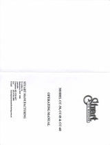
Ice making capacity - Eisproduktionskapazität
AIR COOLED MODELS - LUFTKÜHLUNG
WATER TEMPERATURE - WASSERTEMPERATUR
AMBIENT TEMPERATURE - RAUMTEMPERATUR
ICE PRODUCED PER 24 HRS. - EISWÜRFEL PRODUKTION IN 24 STD.
WATER COOLED MODELS - WASSERKÜHLUNG
WATER TEMPERATURE - WASSERTEMPERATUR
AMBIENT TEMPERATURE - RAUMTEMPERATUR
ICE PRODUCED PER 24 HRS. - EISWÜRFEL PRODUKTION IN 24 STD.
B

D
SD 80 (mm) SD 125 (mm) SD 210 (mm)
A 670 1045 1045
B 572 572 572
C 890 900 1050
➊ CORD SET -
ELEK. KABEL
➋ Ø 20 WATER OUTLET -
WASSERABFLUSS
➌ G3/4" WATER INLET -
WASSEREINLAUF
➍ G3/4" WATER OUTLET -
WASSERABFLUSS
*
➎ G3/4" WATER INLET -
WASSEREINLAUF
*
* Water cooled only
- Nur wassergekuhlt
A
B
C
SD 80
➀
➁
➂➃
➄
A
B
C
SD 125 - 210
➀➁➂➃ ➄

TECHNICAL SPECIFICATIONS - TECHNISCHE ANGABEN
OPERATING PRESSURES - BETRIEBSDRÜCKE
Discharge pressure - Hochdruckbereich
SD 22 SD 23 SD 30 SD 40 SD 60 SD 80 SD 125 SD 210
Air cooled (21°C)
Luftgekühlt (21°C) 8÷9 bar 8÷9 bar 8÷9,5 bar
8,5÷10 bar 8,5÷10 bar
8,5÷9,5 bar 15÷19,5 bar 16÷20 bar
Water cooled
Wassergekühlt 8,5÷10 bar 8,5÷10 bar 8,5÷10 bar 8,5÷10 bar 8,5÷10 bar 9,5 bar 17 bar 17 bar
Suction pressure - Niederdrück
Start / End of freezing cycle - Beginn / Ende der Gefrierfase
SD 22 SD 23 SD 30 SD 40 SD 60 SD 80 SD 125 SD 210
0,8÷0,1 bar 0,8÷0,1 bar 0,8÷0,1 bar 0,8÷0,1 bar 0,8÷0,1 bar 0,8÷0,1 bar 3,6÷1,5 bar 2,4÷1,3 bar
SD22 SD22W SD23 SD23W SD30 SD30W SD40 SD40W SD60 SD60W SD80 SD80W SD125 SD125W SD210 SD 210 W
Electric voltage 230/50/1 230/50/1 230/50/1 230/50/1 230/50/1 230/50/1 230/50/1 230/50/1
Normale Netzspannung -10 ÷ +10% -10 ÷ +10% -10 ÷ +10% -10 ÷ +10% -10 ÷ +10% -10 ÷ +10% -10 ÷ +10% -10 ÷ +10%
Condensation Air Water Air Water Air Water Air Water Air Water Air Water Air Water Air Water
Kühlung Luft Wasser Luft Wasser Luft Wasser Luft Wasser Luft Wasser Luft Wasser Luft Wasser Luft Wasser
Bin Capacity (kg)
Speiker Kapazität (kg) 6,5 12 12 17 20 30 50 80
Net weight (kg)
Netto Gewicht (kg) 28 33 40 45 48 61 94 131
Compressor power HP
Kompressorleistung PS 1/5 1/5 1/5 1/4 3/8 1/2 1 1.5
Running amps
Ampere 2.2 2.2 2.2 2.2 3.2 3.8 5.3 5.5
Start amps
Start Ampere 9 9 9 11 17 20 29 32
Power (Watts)
Leistung (Watt) 340 340 350 380 530 650 1200 2000
Power cons. in 24 hrs (Kwh)
Stromverbrauch in 24 std (Kwh) 7 7 7 7.5 10.5 13 24 35
Wire size (mm
2
)
Kabelanzahl (mm
2
) 3 x 1 3 x 1 3 x 1 3 x 1 3 x 1 3 x 1 3 x 1,5 3 x 1,5
Refrig. charge R 134a (gr)
Kühlmittel Füll. R 134a (gr) 210 190 190 190 260 240 280 240 300 270 450 300 – – – –
Refrig. charge R 404a (gr)
Kühlmittel Füll. R 404a (gr) – – – – – – – – – – – – 630 500 660 500
R
efrigerant metering device
Capillary tube Capillary tube Capillary tube Capillary tube Capillary tube Capillary tube Capillary tube Capillary tube
Kältemittel-Expansionssystem
Kapillarrohr Kapillarrohr Kapillarrohr Kapillarrohr Kapillarrohr Kapillarrohr Kapillarrohr Kapillarrohr
E

M
1. MASTER SWITCH - HAUPTSSCHALTER 9. OPERATING LIGHT -
2. CONDENSER THERMOSTAT - KONDENSATORTHERMOSTAT 10. TIMER MOTOR - TIMER MOTOR
3. BIN THERMOSTAT - SPEICHERTHERMOSTAT 11. HOT GAS VALVE - HEISSGASVENTIL
4. OUTER MICROSWITCH - AUSSERER MIKROSCHALTER 12. WATER INLET VALVE - WASSEREINLAUFVENTIL
5. EVAP. THERMOSTAT - VERDAMPFERTHERMOSTAT 13. WATER PUMP - WASSERPUMPE
6. INNER MICROSWITCH - INNERER MIKROSCHALTER 14. COMPRESSOR - KOMPRESSOR
7. COMPRESSOR SWITCH - KOMPRESSOR SCHALTER 15. FAN MOTOR - LUFTERMOTOR
8. PRESSURE CONTROL - PRESSOSTAT (SD 22 ÷ 60W) (SD 80 ÷ 210 A)
# SD 80 - 125 - 210 AIR COOLED ONLY
NUR SD 80 - 125 - 210 WASSERGEKÜHLTE VERSION
FiG. 1
FiG. 1
FiG. 3
FiG. 5
FiG. 6
FiG. 2
FiG. 4
1
FREEZING CYCLE
3
21
4
56 7
9 101112131415
2
NO NC
COM
3
2 4 NC NO
COM 2
1
31
12
45
8
1
FREEZING CYCLE - TIMING PHASE
3
21
4
56 7
9 101112131415
2
NO NC
COM
3
2 4 NC NO
COM 2
1
31
12
45
8
1
DEFROST CYCLE
3
21
4
56 7
9 101112131415
2
NO NC
COM
3
2 4 NC NO
COM 2
1
31
12
45
8
1
DEFROST CYCLE - BIN FULL
3
21
4
56 7
9 101112131415
2
NO NC
COM
3
2 4 NC NO
COM 2
1
31
12
45
8
1
FREEZING CYCLE - BIN FULL
3
21
4
56 7
9 101112131415
2
NO NC
COM
3
2 4 NC NO
COM 2
1
31
12
45
8
1
RINSING CYCLE
3
21
4
56 7
9 101112131415
2
NO NC
COM
3
2 4 NC NO
COM 2
1
31
12
45
8

GENERAL INFORMATION
AND INSTALLATION
A. INTRODUCTION
This manual provides the specifications and the
step-by-step procedures for the installation, start-
up and operation, maintenance and cleaning for
the SIMAG SD Series Icemakers.
The SIMAG SD cubers are quality designed,
engineered and manufactured.
Their ice making systems are thoroughly tested
providing the utmost in flexibility to fit the needs
of a particular user.
NOTE. To retain the safety and performance
built into this icemaker, it is important that
installation and maintenance be conducted
in the manner outlined in this manual.
B. UNPACKING AND INSPECTION
1. Call your authorized SIMAG Distributor or
Dealer for proper installation.
2. Visually inspect the exterior of the packing
and skid. Any severe damage noted should be
reported to the delivering carrier and a concealed
damage claim form filled in subjet to inspection of
the contents with the carrier’s representative
present.
3. a) Cut and remove the plastic strip securing
the carton box to the skid.
b) Remove the packing nails securing the
carton box to the skid.
c) Cut open the top of the carton and remove
the polystyre protection sheet.
d) Pull out the polystyre posts from the
corners and then remove the carton.
4. Remove the front and the rear panels of the
unit and inspect for any concealed damage.
Notify carrier of your claim for the concealed
damage as stated in step 2 above.
5. Remove all internal support packing and
masking tape.
6. Check that refrigerant lines do not rub
against or touch other lines or surfaces, and that
the fan blades move freely.
7. Check that the compressor fits snugly onto
all its mounting pads.
8. See data plate on the rear side of the unit
and check that local main voltage corresponds
with the voltage specified on it.
CAUTION. Incorrect voltage supplied to
the icemaker will void your parts
replacement program.
9. Remove the manufacturer’s registration
card from the inside of the User Manual and fill-
in all parts including: Model and Serial Number
taken from the data plate.
Forward the completed self-addressed
registration card to SIMAG factory.
C. LOCATION AND LEVELLING
WARNING. This Ice Maker is designed for
indoor installation only. Extended periods
of operation at temperature exceeding
the following limitations will constitute
misuse under the terms of the SIMAG
Manufacturer’s Limited Warranty resulting
in LOSS of warranty coverage.
1. Position the machine bin in the selected
permanent location and tighten the four legs
(SD 30-40-60-80-125-210).
Criteria for selection of location include:
a) Minimum room temperature 10°C (50°F)
and maximum room temperature 40°C (100°F).
b) Water inlet temperatures: minimum 5°C
(40°F) and maximum 40°C (100°F).
c) Well ventilated location for air cooled
models (clean the air cooled condenser at
frequent intervals).
d) Service access: adequate space must be
left for all service connections through the rear of
the ice maker. A minimum clearance of 15 cm
(6") must be left at the sides of the unit for routing
cooling air drawn into and exhausted out of the
compartment to maintain proper condensing
operation of air cooled models.
NOTE. With the unit in “built-in” conditions,
the ice production is gradually reduced in
respect to the levels shown in the graph, up
to a maximum of 10% at room temperatures
higher than 32
°
C.
The daily ice-making capacity is directly
related to the condenser air inlet temperatu-
re, water temperature and age of the machine.
To keep your SIMAG CUBER at peak perfor-
mance levels, periodic maintenance checks
must be carried out as indicated on this
manual.
2. Level the Icemaker in both the left to right
and front to rear directions by means of the
adjustable legs.
D. ELECTRICAL CONNECTIONS
See data plate for current requirements to
determine wire size to be used for electrical
connections. All SIMAG icemakers require a
solid earth wire.
All SIMAG ice machines are supplied from the
factory completely pre-wired and require only
electrical power connections to the wire cord
provided at the rear of the unit.
Page 1

Make sure that the ice machine is connected to
its own circuit and individually fused (see data
plate for fuse size).
The maximum allowable voltage variation should
not exceed -10% and +10% of the data plate
rating. Low voltage can cause faulty functioning
and may be responsible for serious damage to
the overload switch and motor windings.
NOTE. All external wiring should conform to
national, state and local standards and
regulations.
Check voltage on the line and the ice maker’s
data plate before connecting the unit.
E. WATER SUPPLY AND DRAIN
CONNECTIONS
GENERAL
When choosing the water supply for the cuber
consideration should be given to:
a) Length of run
b) Water clarity and purity
c) Adequate water supply pressure
Since water is the most important single ingredient
in producing ice you cannot emphasize too much
the three items listed above.
Low water pressure, below 1 bar may cause
malfunction of the ice maker unit.
Water containing excessive minerals will tend to
produce cloudy colored ice cubes, plus scale
build-up on the interior parts of the water system.
WATER SUPPLY
Connect the 3/4" GAS male of the water inlet
fitting, using the food grade flexible tubing supplied
with the machine, to the cold water supply line
with regular plumbing fitting and a shut-off valve
installed in an accessible position between the
water supply line and the unit.
If water contains a high level of impurities, it is
advisable to consider the installation of an
appropriate water filter or conditioner.
WATER SUPPLY - WATER COOLED MODELS
(SD 80-125-210)
The water cooled versions of SIMAG Ice Makers
require two separate inlet water supplies, one for
the water making the ice and the other for the
water cooled condenser.
Connect the 3/4" GAS male fitting of the water
inlet, using the flexible tubing supplied with the
unit, to the cold water supply line with regular
plumbing fitting and a shut-off valve installed in
an accessible position between the water supply
line and the unit.
WATER DRAIN
Connect the drain fitting with a plastic tube to an
open trapped and vented drain. When the drain
is a long run, allow 3 cm pitch per meter (1/4"
pitch per foot).
On water cooled versions, the water drain line
from the condenser is internally connected with
the drain fitting of the unit.
It is strongly recommended therefore to install a
vertical open vent on unit drain line high point to
ensure good draining and to direct the drain line
to a trapped and vented floor drain receptacle.
NOTE. The water supply and the water drain
must be installed to conform with the local
code. In some case a licensed plumber and/
or a plumbing permit is required.
Page 2

G. INSTALLATION PRACTICE
1. Hand shut-off valve
2. Water filter
3. Water supply line (flexible hose)
4. 3/4" GAS male fitting
5. Vented drain
6. Open trapped vented drain
7. Drain fitting
8. Main switch
9. Power line
7. Have the bolts holding the compressor down
been checked to ensure that the compressor is
snugly fitted onto the mounting pads?
8. Check all refrigerant lines and conduit lines
to guard against vibrations and possible failure.
9. Have the bin liner and cabinet been wiped
clean?
10. Has the owner/user been given the User
Manual and been instructed on the importance of
periodic maintenance checks?
11. Has the Manufacturer’s registration card been
filled in properly? Check for correct model and
serial number against the serial plate and mail
the registration card to the factory.
12. Has the owner been given the name and the
phone number of the authorized SIMAG Service
Agency serving him?
F. FINAL CHECK LIST
1. Is the unit in a room where ambient
temperatures are within a minimum of 10°C
(50°F) even in winter months?
2. Is there at least a 15 cm (6") clearance
around the unit for proper air circulation?
3. Is the unit level? (IMPORTANT)
4. Have all the electrical and plumbing
connections been made, and is the water supply
shut-off valve open?
5. Has the voltage been tested and checked
against the data plate rating?
6.
Has the water supply pressure been checked
to ensure a water pressure of at least 1 bar
(14 psi)? Open the shut-off valve and verify the
absence of water losses from the connections.
WARNING. This icemaker is not designed for outdoor installation and will not function in
ambient temperatures below 10°C (50°F) or above 40°C (100°F).
This icemaker will malfunction with water temperatures below 5°C (40°F) or above 40°C
(100°F).
Page 3

OPERATING
INSTRUCTIONS
START UP
After having correctly installed the ice maker and
completed the plumbing and electrical
connections, perform the following “Start-up”
procedure.
A. Put the icemaker in operation by moving the
unit master switch, located on the cabinet front,
to the ON position.
NOTE. The icemaker control is factory set
with the timer microswitches actuators
dropped off into the initial point of the cam
slot. This setting position allows a proper
water filling.
The unit starts operating in the “defrost cycle”
with the following components being activated:
THE WATER INLET SOLENOID VALVE
THE HOT GAS SOLENOID VALVE
THE CONTACTOR COIL (SD 80-125-210)
THE FAN MOTOR (only SD 22÷40) air cooled
THE COMPRESSOR
THE TIMER MOTOR
B. During the water filling operation, check to
see that the incoming water dribblers, through
the evaporator platen dribbler holes, down into
the sump reservoir to fill it up and also that the
incoming surplus of water flows out through the
overflow pipe into the drain line.
NOTE. If, in the defrost cycle length, the
machine sump reservoir does not get filled
with water up to the rim of the overflow pipe,
remove the front panel and rotate the shaft of
the timer so to cause the dropping of the two
microswitches actuators into the beginning
of the cam slot and check for:
1. The water pressure of the water supply
line, it must be at least 1 bar (14 psig)
Minimum (Max 5 bar-70 psig).
2. The filtering device installed in the water
line that may reduce the water pressure
below the Minimum value of 1 bar (14 psig).
3. Any clogging situation in the water circuit
like the inlet water strainer and/or the flow
control.
OPERATIONAL CHECKS
C. At completion of the water filling phase the
unit initiate automatically the first freezing cycle
with the start up of (Fig.1):
COMPRESSOR
CONTACTOR COIL (SD 80-125-210)
WATER PUMP
FAN MOTOR (in air cooled version)
D. Check to see through the ice discharge
opening that the spray system is correctly seated
and that the water jets uniformely reach the
interior of the inverted mold cups or the exterior
of the evaporator tips; also make sure that the
plastic curtain is hanging freely and there is not
excessive water spilling through it.
E. The ice making process takes place thereby,
with the water sprayed into the molds or onto the
tips that gets gradually refrigerated by the heat
exchange with the refrigerant flowing into the
evaporator serpentine.
During the first portion of the freezing cycle, the
timer assy is standing-by with its microswitches
actuators resting on the raised cam profile
(position that correspond to the end of the defrost
cycle).
F. Then, as the cube size control cut-in point is
reached by the evaporator temperature the control
of the cycle is passed to the timer assy. Whose
raised cam slowly rotates to continue the freezing
cycle (2nd phase) up to its completition.
The components in operation during this 2nd
phase of the cycle are (Fig.2):
COMPRESSOR
CONTACTOR COIL (SD 80-125-210)
WATER PUMP
FAN MOTOR (in air cooled version)
TIMER MOTOR
G. After about 18÷20 minutes from the
beginning of the freezing cycle, in an hypothetic
ambient temperature of 21°C, the defrost cycle
takes place with the hot gas and the water inlet
valves being simoultaneously activated.
The electrical components in operation are (Fig.3):
COMPRESSOR
CONTACTOR COIL (SD 80-125-210)
WATER INLET SOLENOID VALVE
HOT GAS VALVE
TIMER MOTOR
FAN MOTOR (only SD 22÷40) air cooled
H. Check, during the defrost cycle, that the
incoming water flows correctly into the sump
reservoir in order to refill it and that the surplus
overflows through the overflow drain tube.
I. Check the texture of ice cubes just released.
They have to be of the right size with a thickness
of about 7÷8 mm.
If the ice cubes have not the correct size, wait for
a second harvest before attempting any
adjustment by setting the cube size control.
Page 4

By rotating the control setting screw clockwise
the ice cube thickness can be increased; on the
contrary the thickness can be reduced by turning
the setting screw counterclockwise.
If the ice cubes are shallow and cloudy, it is
possible that the ice maker runs short of water
during the freezing cycle second phase or, the
quality of the supplied water requires the use of
an appropriate water filter or conditioner.
J. With the icemaker in the harvest cycle, hold
ice against the bin thermostat control bulb to test
its shut off (Fig.4). This should cause the ice
maker to shut OFF after 30 seconds, 1 minute at
the most, namely when the control bulb tempera-
ture drops to reach +1°C.
NOTE. In case this test is performed during
the freezing cycle, the unit will shut OFF only
at the end of the freeezing cycle and exactly
when the timer switch actuators drop-off into
the cam slot (Fig.5).
Within minutes after the ice is removed from the
sensing bulb, the bulb will warm up to reach +4°C
and consequently will cause the icemaker to
restart from the harvest (defrost) cycle.
K. Instruct the owner/user on the general
operation of the ice machine and about the
cleaning and care it requires.
Page 5

PRINCIPLE OF OPERATION
In the SIMAG cube ice makers the water used to
make the ice is kept constantly in circulation by
an electric water pump which primes it to the
spray system nozzles from where it is diverted
into the molds of the evaporator.
A small quantity of the sprayed water freezes into
ice; the rest of it cascades by gravity into the
sump assembly below for recirculation.
FREEZING CYCLE
The hot gas refrigerant discharged out from the
compressor reaches the condenser where, being
cooled down, condenses into liquid. Flowing into
the liquid line it passes through the drier filter,
then it goes all the way through the capillary tube
where, due to the heat exchanging action, it
looses some of its heat content so that its pressure
and temperature are lowered as well.
Next the refrigerant enters into the evaporator
serpentine (which has a larger I.D. then the
capillary) and starts to boil off; this reaction is
emphasized by the heat transferred by the
sprayed water.
The refrigerant then increases in volume and
changes entirely into vapor.
The vapor refrigerant then passes through the
suction accumulator (used to prevent that any
small amount of liquid refrigerant may reach the
compressor) and through the suction line. In both
the accumulator and the suction line it exchanges
heat with the refrigerant flowing into the capillary
tube (warmer), before to be sucked in the
compressor and to be recirculated as hot
compressed refrigerant gas.
The freezing cycle is controlled by the evaporator
thermostat (which has its bulb in contact with the
evaporator serpentine) that determines the length
of its first portion of the cycle.
When the temperature of the evaporator
thermostat bulb drops to a pre-set value, the
evaporator thermostat changes its contacts (from
3-4 to 3-2) suppling power to the finishing timer
that takes the control of the second timed portion
of the freezing cycle up to its completion.
The length of this second timed portion of the
freezing cycle is pre-fixed and related to the
setting of the upper part of the timer cam.
The electrical components in operation during
the freezing cycle are:
COMPRESSOR
CONTACTOR COIL (SD 80-125-210)
FAN MOTOR (in air cooled version)
WATER PUMP
and during the second phase of freezing cycle
(Time mode) they are joined by the
TIMER
On the SD 60, SD 80, SD 125 and SD 210 air
cooled the refrigerant head pressure, in the course
of the freezing cycle, ranges between 8÷10 bars
SD 60, 8÷9,5 bars SD 80 and 15,5÷20 bars
SD 125-210 being controlled by the hi-pressure
control.
When the discharge pressure rises up to a pre
set value, the pressure control closes its electrical
contacts suppling power to the FAN MOTOR.
As soon as the discharged refrigerant pressure
drops, the pressure control opens its contacts to
temporarely de-energize the fan motor. On others
air cooled models (SD 22÷40) the fan motor is
constantly activated and retain the head pressure
between 8÷10 bars (110÷140 psig).
On the models from SD 22 to SD 60 water cooled
version the same hi-pressure control is used to
intermittently energize a water solenoid valve
located on the water supply line to the condenser.
On the other models SD 80-125-210, in water
cooled version, the discharge pressure is kept
constant by the water regulating valve that meters
the water flow to the condenser.
NOTE. In case of shortage/insufficient cooling
water or air condenser dirty, the operation of
the safety device by hand reset will stop the
machine as soon as the temperature reach
70/75
°
C (160/170
°
F) or the corresponding
pressure. After eliminated the cause of the
stop, put the machine in operation by
pushing the reset button of the safety
thermostat or pressure switch across the
holes in the down/right side of the front panel
or removing it.
At the start of the freezing cycle the refrigerant
suction or lo-pressure lowers rapidly to 0,8 bars
(11 psig) SD 22÷80, 3,6 bars (50 psig) SD 125
and 2,4 bars (34 psig) SD 210 then it declines
gradually - in relation with the growing of the ice
thickness - to reach, at the end of the cycle,
approx. 0,1 bars (1,4 psig) SD 22÷80, 1,5 bars
(21 psig) SD 125, and 1,3 bars (18 psig) SD 210
with the cubes fully formed in the cup molds.
The total length of the freezing cycle ranges from
18 to 20 minutes.
DEFROST OR HARVEST CYCLE
As the electric timer has carried the system
throughout the second phase of freezing cycle,
the defrost cycle starts.
NOTE. The length of the defrost cycle is pre-
determined by the setting of the lower portion
of the timer cam.
In case it is possible to modify the defrost
cycle length through its setting screw.
ATTENTION. The defrost period is the
most critical for the icemaker main
components expecially the compressor.
To avoid to abuse of them it is strongly
recommended to limit the harvest cycle
extension to 4 minutes at the most.
The electrical components in operation during
this phase are:
COMPRESSOR
Page 6

CONTACTOR COIL (SD 80-125-210)
FAN MOTOR (only SD 22÷40) air cooled
WATER INLET SOLENOID VALVE
HOT GAS SOLENOID VALVE
TIMER MOTOR
The incoming water, passing through the water
inlet valve and in its incorporated flow control
(outlet), runs over the evaporator platen and then
flows by gravity through the dribbler holes down
into the sump/reservoir.
The water filling the sump/reservoir forces part of
the left-over water from the previous batch to run
out to the waste through the overflow pipe. This
overflow limits the level of the sump water which
will be used to produce the next batch of ice
cubes.
Meanwhile, the refrigerant as hot gas, discharged
from the compressor, flows through the hot gas
valve directly into the evaporator serpentine by-
passing the condenser.
The hot gas circulating into the serpentine of the
evaporator warms up the copper molds or the
tips causing the defrost of the ice cubes. The ice
cubes, released from the molds, drop by gravity
onto a slanted grid chute, then through a curtained
opening they fall into the storage bin.
At the end of the defrost cycle, both the hot gas
and the water inlet valves close and the machine
starts again a new freezing cycle.
OPERATION - CONTROL SEQUENCE
At the start of freezing cycle, the evaporator
thermostat controls the length of the first part of
the freezing cycle. As its bulb senses a
predetermined temperature, it closes its contacts
to supply power to the timer motor which, in turn,
takes over the control of the freezing cycle.
This second part of the cycle has a pre-fixed time
duration which is relied to the setting extension of
the cam high profile.
NOTE. The evaporator thermostat is factory
set to the number 4 of its setting dial.
In case it is required the setting of the
evaporator thermostat can be made by turning
its adjusting screw located on front side.
With a clockwise rotation of the setting screw
the thermostat cut IN temperature will be
lowered (longer freezing cycle - thicker ice
cube) while, with a counterclockwise rotation
of the screw, the Cut IN temperature rises
(shorter freezing cycle - thiner ice cube).
Once completed the freezing cycle 2nd phase
the system switches automatically into the defrost
cycle which has a pre-fixed length as well.
At completion of the defrost period the unit starts
again a new freezing cycle.
OPERATION - ELECTRICAL SEQUENCE
The following charts illustrate which switches
and which components are ON or OFF during a
particular phase of the icemaking cycle.
Refer to the wiring diagram for a reference.
NOTE. The wiring diagram shows the unit as
it is in the Evaporator Thermostat mode of the
Freezing Cycle.
BEGINNING FREEZE
Electrical components (Loads)....... ON OFF
Compressor........................................ •
Fan motor........................................... •
Hot gas valve ..................................... •
Water inlet valve................................. •
Water pump........................................ •
Contactor coil ..................................... •
Timer motor........................................ •
Electric Controls .............................. ON OFF
Conctats 3-4 evaporator thermostat .. •
Conctats 3-2 evaporator thermostat .. •
Bin thermostat .................................... •
Conctats COM-NO timer microswitch •
Conctats COM-NC timer microswitch •
Pressure control (SD22÷60W) (SD60÷210A)
•
TIMED FREEZE
Electrical components (Loads)....... ON OFF
Compressor........................................ •
Fan motor........................................... ••
Hot gas valve ..................................... •
Water inlet valve................................. •
Water pump........................................ •
Contactor coil ..................................... •
Timer motor........................................ •
Electric Controls .............................. ON OFF
Conctats 3-4 evaporator thermostat .. •
Conctats 3-2 evaporator thermostat .. •
Bin thermostat .................................... •
Conctats COM-NO timer microswitch •
Conctats COM-NC timer microswitch •
Pressure control (SD22÷60W) (SD60÷210A)
••
I° PORTION HARVEST CYCLE
Electrical components (Loads)....... ON OFF
Compressor........................................ •
Fan motor (SD 22÷40 ON)................. •
Hot gas valve ..................................... •
Water inlet valve................................. •
Water pump........................................ •
Contactor coil ..................................... •
Timer motor........................................ •
Electric Controls .............................. ON OFF
Conctats 3-4 evaporator thermostat .. •
Conctats 3-2 evaporator thermostat .. •
Bin thermostat .................................... •
Conctats COM-NO timer microswitch •
Conctats COM-NC timer microswitch •
Pressure control (SD22÷60W) (SD60÷210A)
•
Page 7

II° PORTION HARVEST CYCLE
Electrical components (Loads)....... ON OFF
Compressor........................................ •
Fan motor (SD 22÷40 ON)................. •
Hot gas valve ..................................... •
Water inlet valve................................. •
Water pump........................................ •
Contactor coil ..................................... •
Timer motor........................................ •
Electric Controls .............................. ON OFF
Conctats 3-4 evaporator thermostat .. •
Conctats 3-2 evaporator thermostat .. •
Bin thermostat .................................... •
Conctats COM-NO timer microswitch •
Conctats COM-NC timer microswitch •
Pressure control (SD22÷60W) (SD60÷210A)
•
OPERATING CHARACTERISTICS
On air cooled models during the freezing cycle
the discharge pressure is kept between 8÷10
bars (110÷140 psig) SD 22÷80, 15,5÷20 bars
(215÷280 psig) SD 125-210.
At the same time the suction pressure will
gradually decline, reaching its lowest point just
before harvest. Compressor amps experience a
similar drop.
COMPONENTS DESCRIPTION
A. MASTER SWITCH
Fitted on the front side of the unit cabinet the
master switch has to be used to start-up and to
stop the ice maker operation.
In connection with it there is the green monitor
light.
B. EVAPORATOR THERMOSTAT
The evaporator thermostat with its sensing bulb
intimately in contact with the refrigerant outlet
tube from the evaporator, senses the evaporating
refrigerant temperature (which declines in the
course of the freezing cycle) and when this one
reaches the pre-set value, it switches its contacts
from 3-4 to 3-2 to activate the finishing cycle (2nd
phase) which has a pre-set extension determined
by the large diameter lobe of the timer cam.
C. BIN THERMOSTAT
The bin thermostat, which has its sensing bulb
downward into the storage bin, shuts-OFF
automatically the icemaker when the ice storage
bin is filled and ice contacts its bulb. Being it
connected in series with the front microswitch of
the timer, it causes the unit shut-off only at the
end of the freezing cycle, when the ice cubes are
completed.
After ice is removed from the bin and its bulb
warm-up it allows the unit to restart from the
beginning of the harvest cycle which, in the
circumstance, is more likely a water filling cycle.
D. TIMER
Equipped with two microswitches which plungers
ride one timer cam, the timer is located inside the
control box.
The function of the timer begins when activated
by the cube size control (evap. thermostat).
The large diameter lobe of its cam determines
the 2nd freezing cycle portion length, while the
cam small diameter lobe, determines the time
cycle for the harvest sequence.
The timer cam can be adjusted to vary the defrost
time as required.
WARNING. Never set the defrost time for
longer than 4 minutes as this will
jeopardize the compressor motor
windings.
It goes without saying that an extension of the
defrost period will directly reduce the timed portion
of the freezing cycle and viceversa.
Consequently any variation made at the timer
cam setting requires a compensation adjustment,
very fine and very accurate, of the evaporator
thermostat.
E. COMPRESSOR SWITCH
The compressor switch is located on the edge of
the control box and it can be switched in two
different positions which are:
Operation Supply power directly to the
compressor motor or, on models
SD 80, SD 125 and SD 210, directly
to the contactor coil.
Cleaning Shuts-off the compressor so that
only the water pump and the water
inlet valve will remain in operation.
When positioned on “0 - OFF” the water pump
primes the cleaning or the bactericide solution
allover the unit water system to generate a good
cleaning and sanitizing action of the ice maker.
NOTE. It is recommended to avoid the rinsing,
after the sanitation of the unit water system,
as any bactericide coating, which is beneficial
to limit the bacteria growth, left-over in the
system may be removed.
F. HI PRESSURE CONTROL
Used either on air (SD 60-80-125-210 A) and
water (SD 22÷60W) cooled ice makers it functions
to maintain the head pressure within the preset
values of 8÷10 bars (110÷140 psig) SD 22÷80,
and 15,5÷20 bars (215÷280 psig) SD 125-210,
by intermittently activating the fan motor (in the
air cooled models) and the water inlet valve to the
condenser (in the water cooled models SD 22-
23-30-40-60).
Page 8

L. FAN MOTOR (Air cooled version)
The fan motor, in the SD 60-80-125-210 models
is electrically connected in series with the pressure
control operates during the freezing cycle to draw
cooling air through the condenser fins so to keep
the condensing pressure between the two preset
values 8÷10 bars (110÷140 psig) SD 80 and
15,5÷20 bars (215÷280 psig) SD 125-210.
In the other models SD 22-23-30-40 the fan
motor works continuosly in order to maintain the
condensing pressure between 8÷10 bars
(110÷140 psig).
M. WATER INLET SOLENOID VALVE -
3/4 MALE FITTING
(SD 22 ÷ 60 water cooled version)
A second water inlet solenoid valve, operating
through an automatic hi-pressure control, is used
on water cooled versions to supply water to the
condenser.
When activated it supplies a metered amount of
water to the condenser in order to limit its tempe-
rature and the refrigerant operating high pressure.
N. WATER REGULATING VALVE
(Water cooled version SD 80 ÷ 210)
This valve controls the head pressure in the
refrigerant system by regulating the flow of water
going to the condenser.
As pressure increases, the water regulating val-
ve opens to increase the flow of cooling water.
O. COMPRESSOR
The hermetic compressor is the heart of the
refrigerant system and it is used to circulate and
retrieve the refrigerant throughout the entire
system. It compresses the low pressure refrigerant
vapor causing its temperature to rise and become
high pressure hot vapor which is then released
through the discharge valve.
P. CONTACTOR (SD 80-125-210 only)
Placed inside the control box it operates in order
to close or open the electrical circuit to the
compressor.
G. SAFETY THERMOSTAT/PRESSURE SWITCH
(BY HAND RESET)
Fastened directly onto the refrigerant liquid line
and electrically connected upstream all other
controls, this safety device shut-off the icemakers
when senses that the temperature at the liquid
line has rised to the limit of 75°C (170°F) or
corresponding pressure.
H. WATER SPRAY SYSTEM
It consists of one spray bar with several spray
nozzles on its extension.
The water pumped, is sprayed through its nozzles
in each individual mold or onto each evaporator
tip to be frozen into ice.
I. WATER PUMP
The water pump operates continually throughout
the freezing cycle.
The pump primes the water from the sump to the
spray system and through the spray nozzles
sprays it to the copper molds or onto the
evaporator tips to be frozen into crystal clear ice
cubes. It is recommended that the pump motor
bearings be checked at least every six months.
J. WATER INLET SOLENOID VALVE -
3/4 MALE FITTING
The water inlet solenoid valve is activated by the
timer microswitch only during the defrost cycle.
When energized it allows a metered amount of
incoming water to flow over the evaporator cavity
to assist the hot gas in defrosting the ice cubes.
The water running over the evaporator cavity
drops by gravity, through the dribbler holes of the
platen, into the sump reservoir where it will be
sucked by the water pump and primed to the
spray system.
K. HOT GAS SOLENOID VALVE
The hot gas solenoid valve consists basically in
two parts: the valve body and the valve coil.
Located on the hot gas line, this valve is energized
through the timer microswitch conctats
COM-NC during the defrost cycle.
During the defrost cycle the hot gas valve coil is
activated so to attract the hot gas valve piston in
order to give way to the hot gas discharged from
compressor to flow directly into the evaporator
serpentine to defrost the formed ice cubes.
Page 9

SERVICE DIAGNOSIS
SYMPTOM POSSIBLE CAUSE SUGGESTED CORRECTION
Unit will not run Main switch in OFF position Turn switch to ON position
Safety device intervention Eliminate the stop motivation and
(thermostat - pressure switch) push the reset button or replace.
Loose electrical connections Check wiring
Inoperative bin thermostat Replace thermostat
Compressor cycles Low voltage Check circuit for overloading
intermittently Check voltage at the supply to
the building. If low, contact the
power company
Contactor with burnt contacts Clean or replace
Non-condensable gas in system
Purge the system
Compressor starting device Check for loose wires in starting
with loose wires device
To high room temperature Move the unit in a more
suitable place
Cubes too small Freezing cycle too short Review setting of DIP SWITCH
keys
Capillary tube partially restricted
Blow charge, add new
gas & drier, after evacuating
system with vacuum pump
Moisture in the system Same as above
Shortage of water
See remedies for shortage of water
Shortage of refrigerant Check for leaks & recharge
Inoperative evaporator thermostst
Replace thermostst
Cloudy cubes Shortage of water
See remedies for shortage of water
Dirty water supply Use water softner or water filter
Accumulated impurities cleaner Use SCOTSMAN Ice Machine
Water pump loosing disch. pressure
Check bearings. Replace.
Shortage of water
Water spilling out through curtain
Check or replace curtain
Water solenoid valve not opening
Replace valve
Water leak in sump area Locate and repair
Water flow control plugged Remove and clean
Page 10

Irregular cubes Some jets plugged Remove jet cover and clean
size & some cloudy
Shortage of water See shortage of water
Unit not level Level as required
Cubes too large Freezing cycle too long Adjust evap. thermostat
Inoperative evaporator thermostat Replace thermostat
Decreased ice capacity Inefficient compressor Replace
Leaky water valve Repair or replace
Non-condensable gas in system Purge the system
Poor air circulation or excessive Relocate the unit or provide for
hot location more ventilation
(Red-alarm LED glows)
Overcharge of refrigerant Correct the charge. Purge off slowly
Capillary tube partially restricted Blow charge, add new gas & drier,
after evacuating system with
vacuu pump
Hot gas solenoid valve leaking Replace valve
Undercharge of refrigerant Charge to data plate indication
Discharge head pressure too high See incorrect discharge pressure
Poor harvest Restriction in incoming water line Check water valve strainer and flow
control. If necessary enlarge the
flow control orifice
Water inlet valve not opening Valve coil with open winding
Replace valve
Hot gas valve orifice restricted Replace hot gas valve assy
Discharge head pressure too low See incorrect discharge pressure
Incorrect discharge pressure Inoperative fan pressure control Replace pressostat
Inoperative fan motor Replace
Water regulating valve misadjusted Adjust its setting stem
Excessive water in unit base Water tubing leaking Check. Tighten or replace
SERVICE DIAGNOSIS
SYMPTOM POSSIBLE CAUSE SUGGESTED CORRECTION
Page 11

MAINTENANCE AND
CLEANING INSTRUCTIONS
A. GENERAL
The periods and the procedures for maintenance
and cleaning are given as guides and are not to
be construed as absolute or invariable.
Cleaning, especially, will vary depending upon
local water and ambient conditions and the ice
volume produced; and, each icemaker must be
maintened individually, in accordance with its
particular location requirements.
B. ICEMAKER
The following maintenance should be scheduled
at least two times per year on these icemakers,
by using the SIMAG technical service.
1. Check and clean the water line strainer.
2. Check that the icemaker is levelled in side
to side and in front to rear directions.
3. Clean the water system, evaporator, bin
and spray jets using a solution of Ice Machine
Cleaner.
Refer to procedure C cleaning instructions and
after cleaning will indicate frequency and proce-
dure to be followed in local areas.
NOTE. Cleaning requirements vary according
to the local water conditions and individual
user operation. Continuous check of the clarity
of ice cubes and visual inspection of the
water spraying parts before and after cleaning
will indicate frequency and procedure to be
followed in local areas.
4. With the ice machine and fan motor OFF on
air cooled models, clean condenser using vacuum
cleaner, whisk broom or non metallic brush taking
care to do not damage both the condenser and
ambient temperature sensors.
5. Check for water leaks and tighten drain line
connections. Pour water down bin drain line to be
sure that drain line is open and clear.
6. Check size, condition and texture of ice
cubes. Perform adjustment of the evaporator
thermostat or cube size control by turning its
adjusting screw clockwise for a thicker ice cube
and counterclockwise for a thiner one.
7. Check the bin thermostat to test shut-off.
Put a handfull of ice cubes in contact with its bulb.
This should cause the ice maker to shut off within
20÷30", but only at the end of the freezing cycle!
NOTE. Perform the above check only at the
beginning of the harvest cycle as, during the
freezing cycle the bin thermostat contacts
are bypassed by the front microswitch of the
timer.
When remove the ice cubes from its sensing
bulb the unit will restart after few seconds from
the defrost cycle assuring the filling up of the
water tank.
NOTE. It is possible to adjust the setting
temperature of the bin thermostat by slightly
turning its adjusting screw.
8. Check for refrigerant leaks.
C. CLEANING INSTRUCTIONS OF WATER
SYSTEM
1. Remove the front and the top panels to gain
access either to the control box and to the
evaporator.
2. Wait till the end of defrost cycle then, shut
the unit OFF by means of its master switch.
3. Scoop out all the ice cubes stored into the
bin in order to prevent them from being
contaminated with the cleaning solution then
flush out the water from the sump reservoir by
removing the overflow stand-pipe.
4. Prepare the cleaning solution by diluting in
a plastic container two or three liters of warm
water (45°÷50°C) with a 0,2÷0,3 liters of Ice
Machine Cleaner PIN 00100901.
WARNING. The Ice Machine Cleaner
contains Phosphoric and Hydroxyacetic
acids. These compounds are corrosive
and may cause burns if swallowed, DO
NOT induce vomiting. Give large amounts
of water or milk. Call Physician
immediately. In case of external contact
flush with water. KEEP OUT OF THE
REACH OF CHILDREN
5. Remove the evaporator cover then slowly
pour onto the evaporator platen the cleaning
solution. With the help of a brush dissolve the
most resistant and remote scale deposits in the
platen.
6. Set the compressor switch on "0 - OFF"
position and give power to the unit by the master
switch (Fig.6).
NOTE. With the system in CLEANING mode
the water pump is the only component in
operation to circulate the cleaning solution in
the entire water system.
7. Let the unit to remain in the CLEANING
mode for about 20 minutes then switch OFF the
machine.
8. Flush out the cleaning solution from the
sump reservoir then pour onto the evaporator
Page 12

cavity one or two liters of clean potable water with
the antibacteria solution P/N 26400002 to rinse
and sanitize the molds and the spray system.
If necessary remove the spary bar and nozzles to
clean them separately then refit them.
9. Set back the master switch to ON. The
water pump is again in operation to circulate the
water and the antibacterial solution in order to
rinse the entire water system.
Switch OFF the unit after approx. 10 minutes and
flush out the rinsing water from the sump reservoir.
10. To rotate the timer so that the microswitches
reach the beginning of the defrost cycle (low part
of the cam) give power to the unit by the master
switch.
By doing so are energized the water pump and
the water inlet valve. In this way the incaming
water flow away to fill up the water tank.
11. When the water tank is filled up (water
flowing out from the drain) put the compressor
switch on I ON position to restart the machine in
the automatic mode.
12. Re-fit the evaporator cover and the unit
service panels.
13. At completion of the freezing and harvest
cycle make sure of proper texture and clearness
of the ice cubes and that, they do not have any
acid taste.
ATTENTION. In case the ice cubes are
cloudy, white and have an acid taste, melt
them immediately by pouring on them
some warm water.
This to prevent somebody from using
them.
14. Wipe clean and rinse the inner surfaces of
the storage bin.
REMEMBER. To prevent the accumulation
of undesirable bacteria it is necessary to
sanitize the interior of the storage bin with
an anti-algae disinfectant solution every
week.
Page 13
/