Page is loading ...

WIRELESS MICROPHONE SYSTEMS
GENERAL
Shure L Series wireless microphone systems are single-channel
systems operating in the VHF band between 169.445 MHz and
216.100 MHz. Each system consists of a hand-held L2 Microphone-
Transmitter or an L11 Body-Pack Transmitter with a lavalier micro-
phone or instrument adapter cable, and an L3 or L4 Receiver. Each
component is briefly described below.
L2 Hand-Held Microphone-Transmitter.
The L2 is a hand-held
microphone with a built-in transmitter. It features superb frequency
response, extended dynamic range, a batterytest light, and heavy-
duty grille with built-in pop filter. The L2 is supplied in four models:
l
L2/58, which includes the world-famous Shure SM58 cardioid
dynamic microphone
l
L2/BETA58®, which includes the Shure BETA58 supercar-
dioid dynamic microphone
l
L2/87, which includes the Shure SM87 supercardioid condens-
er microphone
l
L2/BETA87, which includes the Shure BETA87 supercardioid
condenser microphone
L11 Body-Pack Transmitter. The L11 features extended dy-
namic range, a battery test light, noiseless muting, and a rugged
case.
Lavalier Microphone.
A lavalier electret condenser microphone
plugs into the L11 Body-Pack Transmitter. Five microphone models
are available with the L Series body-pack systems: the WL83A,
WL84A, and WL93 lavalier type microphones, the WM98 instru-
ment microphone, and the WCM16 headworn microphone. Each
microphone features optimized frequency response, low distortion
and low RF susceptibility.
WA302 Instrument Adapter Cable. The WA302 instrument
adapter cable is used with electric guitars and other electric instru-
ments instead of a lavalier microphone. The WA302 plugs into the
microphone input on the L11 Body-Pack Transmitter.
L3 Receiver.
The L3 offers interference-free operation, superior
quieting, and highly effective noise reduction. It has a removable
¼-wave antenna and is rack-mountable with an optional mounting
kit.
L4 Diversity Receiver.
The L4 includes all of the features of the
L3 receiver plus Shure’s exclusive MARCAD® circuitry. MARCAD
(MAximum Ratio Combining Audio Diversity) goes beyond stan-
dard switching RF diversity. It constantly monitors the two signals
and combines them when both signals are usable. The result is in-
creased RF gain, improved reception, and exceptional freedom
from dropouts.
PERFORMANCE CHARACTERISTICS
Operating Frequencies.
A total of 28 frequencies, computer-se-
lected for interference-free operation, are readily available. Other fre-
quencies can be ordered on a special basis.
Multiple Miking.
Up to ten L Series systems can be operated in a
single sound installation, simultaneously and without intermodula-
tion problems. However, each system must operate at a different
frequency.
Transmitter Range.
The maximum operating range for any L Series
system is normally 100 meters (330 feet), although operation at 300
meters (1000 feet) is often possible. Conditions at the installation site
(reflective surfaces, obstacles, radio interference, etc.) will ultimately
dictate a system’s limits. For best results, keep the distance between
the transmitter and the receiver as short as possible.
Power Requirements. The L3 and L4 receivers are supplied
with separate PS20 adapter for 120 VAC, 60 Hz power or a PS20E
adapter for 220/240 VAC, 50 Hz power. The receivers can also be
powered by any filtered 12.5 - 18 VDC power source. The L2 and
L11 transmitters operate on a 9-volt alkaline or 8.4-volt nicad bat-
tery. Battery life depends on the type and brand of battery.
Copyright 1994, Shure Brothers Inc.
27A8441 (NJ)
222 HARTREY AVENUE, EVANSTON, ILLINOIS 60202-3696 U.S.A.
Printed in U.S.A.

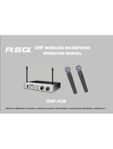
L11 BODY-PACK TRANSMITTER FEATURES AND
CONTROLS (Figure 2)
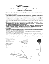
L2 HAND-HELD MICROPHONE-TRANSMITTER
FEATURES AND CONTROLS
(Figure 1)
L11 BODY-PACK TRANSMITTER FEATURES AND CONTROLS
FIGURE 2
L2 MICROPHONE-TRANSMITTER FEATURES AND CONTROLS
FIGURE 1
1.
Grille: Protects the microphone cartridge and helps reduce
breath sounds and wind noise.
Note:
The grilles for the L2/58, L2/BETA58, the L2/87, and the
L2/BETA87 differ in appearance.
2.
Antenna (Internal; not shown):
The L2’s internal antenna con-
sists of a special wire loop attached to a printed circuit board.
3.
MIC ON/OFF Switch:
Mutes the microphone without turning
the transmitter off, so no “pop” sounds occur. Also prevents re-
ceiver from picking up unwanted signals.
4.
POWER ON/OFF Switch:
Turns transmitter on and off.
5.
Battery Test Light:
glows when the POWER switch is turned
on and a “good” battery is installed. When this light starts to
dim, the transmitter will continue to operate for a short time
(typically 1/2 to 1 hour). If this light does not glow, the battery
should be replaced.
6.
Battery Compartment:
Unscrewing the handle and sliding it
downward exposes the battery compartment and the audio
GAIN Switch (8).
7.
Frequency Identification Label:
Located inside the battery
compartment, this label lists the transmitter’s operating fre-
quency.
8.
Audio Level Control Switch:
Controls the audio level of the
microphone.
1.
Microphone Input Connector: This 4-pin, miniature male
connector mates with Switchcraft TA4F connectors. The mi-
crophone cable and the WA302 instrument adapter cable
plug into this connector.
2.
Battery Test Light:
glows when the POWER switch is turned
on and a “good” battery is installed.
If this light does not glow,
the transmitter will not work.
3.
MIC ON/OFF Switch: “Mutes” the microphone without turn-
ing the transmitter off, so no “pop” sounds occur.
4.
POWER ON/OFF Switch:
Turns transmitter on and off
5.
Antenna: A flexible antenna wire is permanently attached to
the bottom of the body-pack transmitter. For proper opera-
tion, the antenna must hang in the vertical position, not coiled
or bundled.
6.
Audio Level Control:
Allows audio level adjustments for vari-
ous sound sources. A small screwdriver is supplied to make
adjustments.
7.
Frequency Identification Label:
Identifies the transmitter’s
original operating frequency.
8.
Belt Clip: Allows the transmitter to be worn on a belt, waist-
band or guitar strap. It can be removed, if desired.
9.
Microphone Cable Connector:
Switchcraft TA4F 4-pin con-
nector (female) plugs into 4-pin socket on body-pack trans-
mitter.
10.
Lavalier Microphone (WL93 shown):
Condenser lavalier
microphone supplied with a mount that clips onto a tie, lapel,
or acoustic instrument.
11.
Battery Compartment:
Hinged cover on bottom surface ex-
poses the battery compartment.
12.
WA302 Instrument Adapter: Plugs into electric guitar and
other electric instruments.
2

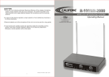
L3 AND L4 RECEIVER FEATURES AND CONTROLS (Figure 3)
1.
2.
3.
4.
5.
6.
1.
2.
3.
4.
5.
7.
8.
9.
10.
11.
12.
FRONT
REAR
MODEL L3 RECEIVER
MODEL L4 RECEIVER
L3 AND L4 RECEIVERS, EXTERNAL FEATURES AND CONTROLS
FIGURE 3
POWER ON Indicator: This green LED glows when power is
RECEIVER SETUP
turned on.
L3 and L4 Receiver Installation
RF Signal Indicator (L3 Only):
Yellow light glows to show that
received RF signal exceeds squelch threshold level. This light
is not an indicatorof signal strength, although a barely flickering
light indicates marginally acceptable signals.
AUDIO PEAK Indicator:
Red light glows to show approaching
audio overload condition. Normal operation is shown by occa-
sional glowing of light on loud signals; constant glowing indi-
cates excessive audio level and need to lowertransmitter Audio
Level control.
VOLUME Rotary Control: Determines signal level at receiver
OUTPUT connector(s). Also permits matching signal level to
input level requirements of a mixer or amplifier.
POWER On/Off Button:
Applies power from the DC power in-
put jack to the receiver. Green POWER light glows and remains
on when power is applied to the receiver.
DIVERSITY Signal Indicators (L4 Only):
Yellow lights glow to
show usable RF signals are being received from antenna A, an-
tenna B, or both.
AUDIO NORMAL Indicator (L4 Only): Green light flashes,
showing normal audio operation.
Phone Jack Output Connector: ¼-inch phone jack provides
unbalanced output to audio mixer or amplifier.
12 VDC Negative Ground Coaxial Power Jack:
Accepts pow-
er from the supplied AC adapter, or from any well-filtered 12-18
VDC supply.
SQUELCH MIN-MAX Screwdriver Control:
The squelch circuit
automatically quiets or “mutes” the receiver when no transmitter
signal is being received. The squelch control is factory-set for best
operation in most applications, but can be adjusted for unusual
conditions (see Receiver Squelch paragraph).
XLR Output Connector (L4 Only): XLR connector provides
balanced low-impedance microphone-level output.
Antenna Connector: SO-239 UHF-type connector provides
connection to ¼-wave vertical antenna.
Place the receiver in its operating location, either on a horizontal
surface or in a rack panel (rack panel mounting brackets are
supplied with L4 receivers). If placed on a horizontal surface,
attach the four adhesive bumpers to the bottom corners of the
receiver. If installing an L4 receiver in a rack panel, remove the
screws on each side of the receiver, position the mounting
brackets supplied with the L4 over the holes, and secure the
brackets with the two removed screws and the two screws
supplied with the L4.
Connect the supplied PS20 AC adapter to the POWER input
connector on the rear panel. Plug the AC adapter into a 120
VAC, 60 Hz power source.
NOTE: If the receiver is to be plugged into a 230 VAC, 50 Hz
power supply, connect the PS20E AC adapter to the POWER
input connector on the rear panel.
Attach the supplied ¼-wave antennas to the ANTENNA connec-
tor(s). Make sure the antennas are pointed upward.
IMPORTANT
The receiver antenna(s) should be within line-of-sight
of the transmitter. Obstructions or reflective objects will degrade sys-
tem performance. Improved L4 diversity performance may be ob-
tained by remotely locating one or both antennas so that they are
separated by 1.5 meters (60 inches) or more. Optional Shure
WA380 ½ Wave High Gain Antennas are recommended for such
applications. They may be mounted directly on the receiver or re-
motely located using two Shure WA420 Antenna Cable Kits. With
rack-mounted receivers, both antennas mustextend above the rack
cabinet or be remotely located. To operate as many as four receiv-
ers with only two antennas, use the Shure WA404 amplified Anten-
na/DC Power Distribution System.
Obtain an audio cable (Shure WA410 or equivalent) with ap-
propriate connectors to connect the receiver to audio mixer or
amplifier.
NOTE:
To connect the L3 output to the high-impedance input of
an audio mixer or amplifier, use a cable with ¼-inch phone
plugs on both ends.
Connect the cable between the OUTPUT connector on the re-
ceiver and the mixer/amplifier input.
NOTE:
When a long cable run is required, or when the mixer input
has phantom power present, add a low- to high-impedance line
matching transformer at the L3 output jack (Shure A95U or equiva-
lent). A conventional low-impedance microphone cable can then
be used between the A95U output and the mixer input.
3

TRANSMITTER SETUP
L2 Microphone-Transmitter Battery Installation
1.
Make sure the transmitter POWER ON/OFF switch is in the
OFF position.
2. While holding the upper part of the transmitter, unscrew (turn
counterclockwise) the handle and slide it downward, as shown
below in Figure 4.
3.
L2 MICROPHONE-TRANSMITTER BATTERY INSTALLATION
FIGURE 4
Insert a fresh 9-volt alkaline battery and make sure the battery
polarity (“+/-”) is correct. A fresh 9-volt alkaline battery should
provide a minimum 14-20 hours of operation. However, nickel-
cadmium batteries will only provide approximately 3 hours of
operation.
IMPORTANT:
Use only a 9-volt alkaline battery or a heavy-duty,
rechargeable 8.4-volt nicad battery. Carbon-zinc and zinc-chlo-
ride batteries will not provide sufficient power for proper operation
and are not recommended.
L11 Body-Pack Transmitter Battery Installation
1. With the transmitter POWER ON/OFF switch in the OFF position,
press down on the OPEN side of the battery compartment cover,
slide it back and flip it open, as shown below in Figure 5.
L11 BODY-PACK TRANSMITTER BATTERY INSTALLATION
FIGURE 5
2.
Insert a fresh 9-volt alkaline battery, and make sure the battery po-
larity (“+/-”) is correct. A fresh 9-volt alkaline battery should pro-
vide a 14 - 20 hours of operation. However, nickel-cadmium bat-
teries will only provide 1.5 to 2 hours of operation.
IMPORTANT:
Use only a 9-volt alkaline battery or a heavy-duty,
rechargeable 8.4-volt nicad battery. Carbon-zinc and zinc-chlo-
ride batteries will not provide sufficient power for proper operation
and are not recommended.
Checking the Transmitter Battery
To check the battery in either the L11 or L2 transmitter, turn the
transmitter POWER switch on and observe the Battery Test light.
The light should be bright and clearly visible, indicating adequate
voltage. If the light is dim, the battery voltage has dropped below 6.5
volts and the battery should be replaced (alkaline or recharged nick-
el-cadmium only). If the light does not glow at all, the transmitter will
not operate and the battery should be replaced.
L11 Body-Pack Transmitter Microphone Connections
1.
Plug the connector end of the lavalier microphone cable or the
WA302 instrument adapter cable into the 4-pin connector on the
Body-Pack Transmitter. See Figure 6 below.
L11 BODY-PACK TRANSMITTER CABLE CONNECTION
FIGURE 6
2.
If you are using a lavalier microphone, press the microphone into
the necktie mounting block and clip it to your tie or lapel. If you are
using an electronic instrument, plug the WA302 instrument adapt-
er cable into your guitar or instrument.
IMPORTANT:
Other manufacturer’s microphones specified for
wireless use are generally not compatible, as supplied, with
Shure wireless systems.
Connecting Other Microphones to the L11 Transmitter
Any Shure lavalier microphone or accessory cable with a Switch-
craft TA4F type 4-pin (female) connector will plug directly into the
transmitter input connector. Many other condenser microphones
will operate using the transmitter’s regulated +5 VDC power avail-
able on pin 2. Low-impedance dynamic or ribbon microphones with
pin 2 output can be used with an optional WA310 adapter cable.
See Figure 7 below.
NOTE: Condenser microphones requiring phantom power will
not normally operate with the L11/WA310 transmitter configura-
tion.
TRANSMITTER INPUT
CONNECTOR
1 - GROUND
2 - +5 VDC
3 - AUDIO (FOR DYNAMIC MICS OR INSTRU-
MENTS)
4 - 20K TO GROUND (MATING PLUG SHORTS
TO PIN 3 FOR CONDENSER MICS)
L11 TRANSMITTER CONNECTIONS
FIGURE 7
4

OPERATING THE SYSTEM
1.
Turn on the receiver by pressing the receiver POWER button.
2.
Slide the transmitter POWER and MIC switches to the “on” posi-
tion. The green POWER light on the transmitter should glow, in-
dicating a good battery.
3.
Verify that the yellow RF light (L3) or the yellow DIVERSITY
lights (L4) glow steadily. This indicates that the transmitter sig-
nal is being received.
NOTE: Flickering RF/DIVERSITY lights indicate marginal op-
eration.
4. Talk into the microphone (or play a musical instrument) and ob-
serve the following on the receiver:
l
Steady glow of the RF light (L3) or DIVERSITY A or B lights (L4).
If these lights are not glowing, the system’s range has been ex-
ceeded, or there are obstructions in the transmission path.
l
Steady glowing or flashing AUDIO NORM light (L4).
l
Flashing of the red AUDIO PEAK light only on loud peaks. If
this indicator is always on or is always off, refer to the “Audio
Gain Adjustments” paragraph below.
5. Adjust the receiver VOLUME control until the output level is
proper for the mixer or amplifier input. Turning the VOLUME
control counterclockwise decreases output; turning it clockwise
increases output. Note that the L4 VOLUME control affects
both balanced and unbalanced outputs.
6.
Continue speaking or singing into the microphone (or playing an
instrument) while moving around the performing area, to make
sure no problems such as feedback or signal loss occur. Audio
signal strength should only change when source volume levels
change, not when the user moves around the performing area.
NOTE: Every wireless microphone installation is unique, and
can present a variety of problems. Never attempt a live perfor-
mance without a “walk-through” test first. If major changes were
made since the last walkthrough (equipment, scenery, etc.),
check the wireless microphone system again as close to perfor-
mance time as possible.
Audio Gain Adjustments
If the AUDIO PEAK light is constantly glowing, the audio signal is
too loud and may be distorted. If the AUDIO PEAK light never
glows, the audio signal is too low and may be noisy. To correct these
problems, adjust the transmitter as follows:
l
L11 Body-Pack Systems:
Using the supplied screwdriver, ad-
just the audio level control on the body-pack transmitter until the
receiver AUDIO PEAK light flickers occasionally while the mi-
crophone is in use. See Figure 8 below.
L11 BODY-PACK TRANSMITTER AUDIO GAIN ADJUSTMENT
FIGURE 8
IMPORTANT:
Gain adjustments must be made while using the
microphone (or playing an instrument) at a typical level.
l
L2 Hand-HeldSystems:
Unscrew the handle of the L2 and lo-
cate the audio level control next to the battery holder. Select the
LO or HI gain position so that the receiver AUDIO PEAK light
flickers only occasionally. See Figure 9.
L2 MICROPHONE-TRANSMITTER AUDIO GAIN ADJUSTMENT
FIGURE 9
Changing Receiver Squelch Control Settings
The receiver SQUELCH control is factory preset for optimum
performance.
Normally, no further adjustment to the SQUELCH
control is required. However, if adjustment is necessary (as indi-
cated by continued glowing of the RF or AUDIO PEAK lights (L3) or
DIVERSITY A or B, AUDIO NORM or PEAK lights (L4) with the
transmitter off), proceed as follows:
1.
Position the wireless system as it will be during use.
2. Turn off the wireless transmitter POWER switch.
3. Turn the receiver VOLUME control fully counterclockwise and
turn the POWER switch on.
4. Observe the receiver lights. If the RF or AUDIO PEAK lights
(L3) or DIVERSITY A or B, AUDIO NORM or PEAK lights (L4)
are glowing, slowly turn the SQUELCH Control clockwise until
the lights turn off. Continue turning thecontrol clockwise slight-
/y past this point.
5. To return the SQUELCH control to the factory setting, rotate it
back to the midrange (straight up) position.
NOTE: Turning the SQUELCH control toward MIN (counter-
clockwise) makes the receiver more sensitive and increases
the system’s range. However, it also allows the microphone sig-
nal to become noisier before it is muted. Turning the control to-
ward MAX (clockwise) reduces the system’s range, but pre-
vents interfering signals and noise from overriding the squelch
when the transmitter signal is not present.
Feedback Control
The following guidelines can be used to control feedback:
l Make sure the loudspeakers are positioned properly relative to
the microphone
l Maintain gain controls at the lowest levels required for the de-
sired sound
l Use good microphone technique
l Make sure the sound system is properly equalized
Controlling Multipath Transmission (“Dropout”)
Multipath transmission (or “dropout”) occurs when the direct RF
signal and a reflected signal arrive at the receiver at different times
or out of phase, or when the signal path is obstructed. The result is
excessive noise or temporary signal loss. To avoid multipath, ob-
serve the following precautions:
l Maintain line-of-sight transmission. The transmitter user should
always be able to see at least one of the receiver antenna(s).
l
Keep the distance between the transmitter and the receiver an-
tennas as short as possible.
l Avoid operating the wireless microphone around reflective sur-
faces, especially metal surfaces.
l
Make sure both transmitter and receiver antennas are posi-
tioned vertically.
5

TROUBLESHOOTING
lf the installation and setup instructions have been followed
and a problem still exists, perform the troubleshooting proce-
dures in the table below. If the problem persists, contact your
dealer or Shure’s Service Department.
PROBLEM
No receiver sound; yellow RF
light on L3 Receiver not glow-
ing; neither DIVERSITY light
on L4 Receiver glows.
No receiver sound; RF light on
L3 Receiver glows; one or both
DIVERSITY lights on L4 Re-
ceiver glow.
Noise from receiver with trans-
Look for strong local interference sources such as other radio signals. (Nearby electrical motors or lighting
mitter off; DIVERSITY lights
equipment could also be the problem.) Reposition antennas.
glowing or flickering.
SQUELCH control may be set too low. Readjust as necessary.
Received signal is noisy or
contains extraneous sounds
with transmitter on.
Look for strong local interference sources such as other radio signals, nearby motors or lighting equipment. Re-
move the source of interference, reposition the receiver, or reposition the antennas.
Two transmitters may be operating on the same frequency. Locate and turn one off.
Signal may be too weak. Reposition antennas. If possible, move them closer to the transmitter. If necessary,
install optional ½ wave high gain antenna(s) (WA380) and antenna cable kit (WA420).
SQUELCH control may be set too low. Readjust as necessary (See Figure 5).
AUDIO GAIN may be set too low. Increase for L11 (See Figure 8) switch to HI position for L2 (See Figure 9).
SOLUTION
Make sure POWER switches on transmitter and receiver are ON.
Check transmitter battery and receiver power source.
Check receiver squelch setting.
Check receiver antenna connection(s).
Make sure transmitter and receiver are on same operating frequency.
Make sure transmitter and receiver antennas follow line of sight. If necessary, reduce the distance between the
transmitter and the receiver. Higher gain antennas (WA380) may be required.
With the microphone POWER switch ON, turn up the receiver volume control.
Make sure transmitter MIC switch is ON.
Make sure the microphone cable plug is locked into the transmitter connector.
Check connection between receiver and microphone mixer.
Talk into the microphone and observe the receiver AUDIO light. If the light glows, the problem is elsewhere
in sound system.
SPECIFICATIONS
l OVERALL SYSTEM
RF Carrier Frequency Range
169 to 216 MHz
Frequency Stability
0.005%, Crystal-Controlled
Total Harmonic Distortion
0.3% typical (ref. 15 kHz deviation, 1 kHz modulation)
Working Range (average conditions)
30 m (100 ft.) with >90 dB dynamic range; 90 m (300 ft.) with >80
dB dynamic range; 300 m (1,000 ft.) at 60 dB
Modulation
±15 kHz deviation compressor-expander system with pre- and
de-emphasis
Dynamic Range
>102 dB A-weighted
Audio Frequency Response
50 to 15,000 Hz, ±2 dB
NOTE:
Overall system frequency response depends on the micro-
phone element used. Refer to the response curves in Figure 9 or
the separate lavalier microphone data sheets.
Operating Temperature Range
-20° to 50° C (-4° to 122° F)
l
L3 AND L4 RECEIVERS
RF Sensitivity
L3: 0.35 µV for 12 dB SINAD typical
L4: 0.45 µV for 12 dB SINAD typical
Image Rejection
65 dB typical
Spurious Rejection
75 dB typical
Ultimate Quieting (ref. 15 kHz deviation)
>94 dB A-weighted
Squelch Quieting (ref. 15 kHz deviation)
>94 dB A-weighted
Squelch Threshold
L3: 2.0 µV, adjustable
L4: 2.0 µV, adjustable
output
L3: -2 dBV (unloaded; volume full clockwise: full deviation);
3.3 kΩ output impedance. Compatible with high- and low-imped-
ance inputs.
L4: -2 dBV, 1 kΩ output impedance, unbalanced; -18 dBV, 150
output impedance, balanced (volume full clockwise; full devi-
ation; unloaded)
Power Requirements
L3: 12 - 18 VDC nominal (negative ground), 85 mA
L4: 12.5 - 18 VDC (negative ground), 165 mA
Both models supplied with PS20 external AC adapter for 110
VAC, 60 Hz power (PS20E adapter for 220/240 VAC supplied
with E versions)
Antenna
L3: Sheathed stainless steel, 1/4-wavelength, 406 mm (16 in.)
L4: 428 mm (16.85 in.), PL-259 UHF connectors
Overall Dimensions (excluding antennas)
L3: 42.9 mm H x 176 mm W x 127 mm D (11-11/16 x 6-15/16 x 5 in.)
L4: 44.5 mm H x 435 mm W x 200 mm D (1-3/4 x 17-1/8 x
7-7/8 in.)
Weight
L3: 556 grams (1 lb 3.5 oz)
L4: 1.36 kilograms (3 lb)
Certification
Type-accepted under FCC Part 15
FCC ID: DD4DL3 (L3), DD4DL4 (L4)
Certified by DOC under RS121, Issue 2, as a guide
6

•
TRANSMITTERS
RF Power Output
50 mW maximum
Input Impedance (L11 only)
Actual: 17 kΩ pin 4 wired to pin 3 for condenser microphones;
100 kΩ, pin 4 open for dynamic microphone or instrument pickup
Gain Adjustment Range
L11: 40 dB
L2: 15 dB
Antenna
L11 : Attached, 386 mm (15.2 in.), omnidirectional, flexible wire
L2:
Integral loop antenna mounted to RF printed circuit board
Power
Battery Type:
9 V alkaline (Duracell MN1604A recommended);
8.4 V nicad optional
Battery Life: 14-20 hours minimum typical for 9 V alkaline;
3 hours per charge typical for 8.4 V nicad
Current Drain
28 mA typical
Overall Dimensions (excluding antenna and belt clip)
L2/58, L2/BETA 58: 237 mm x 51 mm (9-5/16 x 2 in.)
L2/87, L2/BETA 87: 213 mm x 50.8 mm (8-3/8 x 2 in.)
L11: 82.6 mm High x 63.5 mm Wide x 26.2 mm Deep
(3-1/4 x 2-1/2
x
1-1/32 in.)
Net Weight
Model
L11
L2/58
L2/BETA 58
L2/87
L2/BETA 87
Without Battery With Battery
2.8 oz (80.5 g) 4.3 oz (123 g)
11.6 oz (330 g) 13.1 oz (372.5 g)
11.6 oz ( 330 g) 13.1 oz (372.5 g)
15.8 oz (450 g) 17.3 oz (492.5 g)
15.8 oz (450 g)
17.3 oz (492.5 g)
L2 Transducer Type
L2/58, L2/BETA 58: Dynamic
L2/87, L2/BETA 87: Condenser (electret bias)
Audio Polarity
L11 with WL84A, WL93, WCM16 or WM98 Shure Wireless
Microphones:
Positive pressure on microphone diaphragm pro-
duces positive voltage (with respect to ground) on tip of receiver
output (L3), auxiliary output (L4), or pin 2 with respect to pin 3 of
low-impedance output (L4)
L11 with WA310 or WA302 Cable: Positive voltage applied to
pin 3 of WA310 XLR connector, or to tip of WA302 phone plug
produces positive voltage on tip (with respect to ground) of re-
ceiver output (L3), on tip with respect to ground of unbalanced
output (L4), and on pin 2 (with respect to pin 3) of balanced output
(L4)
L2/58, L2/BETA 58, L2/87, and L2/BETA
87: Positive pressure
on microphone diaphragm produces positive voltage on tip (with
respect to ground) of receiver output (L3), on tip with respect to
ground of unbalanced output (L4), and on pin 2 (with respect to
pin 3) of balanced output (L4)
L2 Polar Patterns (See Figure 10 below)
Note: All measurements taken at a distance of 2 feet from the
sound source. Refer to separate data sheets for L11 lavalier micro-
phone polar patterns and frequency response curves.
MODEL L2/58
MODELL2/BETA
58
MODEL L2/BETA 87
FIGURE 10
7

L2 Microphone-Transmitter Frequency Response
(See Figure 11 below) NOTE: All measurements taken at a dis-
tance of 2 ft. from sound source
MODEL L2/58
FREQUENCY IN Hz
MODEL L2/BETA 87
FIGURE 11
Certification
Type-accepted under FCC Parts 74 and 90
FCC ID: DD4L11A (L11, 166-174 MHz), DD4L11 (L11, 174-216
MHz), DD4L2A (L2, 166-174 MHz), DD4L2 (L2, 174-216 MHz)
Certified by DOC under RS214, as a guide (174-216 MHz only)
L3 & L4 comply with FCC Part 15 under Notification Procedures
FURNISHED ACCESSORIES
Screwdriver (L11)
...............................
65A1659
Rack Panel Bracket (L4)
.........................
48A8012
Instrument Adapter Cable (L11)
.....................
WA302
OPTIONAL ACCESSORIES
Line Matching Output Transformer (L3)
................
A95U
Instrument Adapter Cable (L11)
.....................
WA302
Microphone Adapter Cable (L11)
....................
WA310
Switchcraft TA4F Connector (L11)
...................
WA330
In-Line Audio Switch (L11)
..........................
WA360
Swivel Adapter (L2)
...............................
.WA370A
½-Wave Antenna Assembly (169-185 MHz) .........
WA380A
½-Wave Antenna Assembly (185-200 MHz) .........
WA380B
½-Wave Antenna Assembly (200-216 MHz) .........
WA380C
Single/Double Rack Mount Kit (L3)
...................
WA390
Antenna Distribution System (L3, L4)
.................
WA400
Antenna/Power Distribution System
..................
WA404
Receiver-Mixer Cable (1.8 m – 6 ft.) (L3, L4)
...........
WA410
Antenna Cable Kit (L3, L4)
.........................
WA420*
Antenna Rack Mount Kit (L4)
........................
WA440
*Includes cable, UHF adapter, and wall-mount bracket.
REPLACEMENT PARTS
SM58 Cartridge
.....................................
R158
BETA 58 Cartridge
...................................
R160
SM87 Cartridge
....................................
R128
BETA 87 Cartridge.
..................................
N/A*
SM58 Grille
BETA 58 Grille
....................................
RK143G
.............................
RK265G
SM87 Grille
.....................................
90E3014
BETA 87 Grille
.................................
90B3955
L11 Belt Clip
...................................
53A8247A
L3, L4 AC Adapter
..........
PS20 (120V), PS20E (220/240V)
L3, L4 ¼-Wave Antenna Assembly
................
90C8342
*Replacement cartridges for the Beta 87 are available only through factory exchange or through
Shure Distribution Centers.
INFORMATION TO THE USER
The L3 and L4 Receivers have been tested and found to comply with
the limits of Part 15 of the FCC Rules. These limits are designed to pro-
vide reasonable protection against harmful interference in a residential
installation. Operation is subject to the condition that this equipment
does not cause harmful interference.
This equipment generates, uses and can radiate radio frequency en-
ergy and, if not installed and used in accordance with the instructions,
may cause harmful interference to radio communications. However,
there is no guarantee that interference will not occur in a particular
installation. If this equipment does cause harmful interference to radio
or television reception, which can be determined by turning the equip-
ment off and on, the user is encouraged to try to correct the interference
by one or more of the following measures:
(1) Reorient or relocate the receiving antenna.
(2)
Increase the separation between the L3 or L4 receiver and the radio
or TV receiver.
(3) Connect the equipment into an outlet on a circuit different from that
to which the receiver is connected.
(4) Consult a dealer or an experienced radio/TV technician for help.
CAUTION: Changes or modifications not expressly approved by
Shure Brothers, Inc. could void your authority to operate the equipment.
FCC LICENSING INFORMATION
Shure Model L11 and L2 Transmitters are Type-Accepted under FCC
Parts 90 and 74. IMPORTANT: Licensing of Shure wireless micro-
phone equipment is the user’s responsibility, and licensability de-
pends on the user’s classification and application, and on the se-
lected frequency.
Shure strongly urges the user to contact the appropri-
ate telecommunications authority concerning proper licensing.
8
/