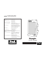
Anchor Voyager is a portable sound system that's perfect for musicians, presenters, and anyone who needs to amplify their voice or audio. With its built-in rechargeable battery, you can use it for hours without having to worry about finding an outlet. The Voyager has two microphone inputs, an auxiliary input, and a line output, so you can connect a variety of audio sources. It also has a built-in wireless receiver, so you can use it with a wireless microphone (sold separately). The Voyager's sound is clear and powerful, and it's easy to operate, making it a great choice for any application.
Anchor Voyager is a portable sound system that's perfect for musicians, presenters, and anyone who needs to amplify their voice or audio. With its built-in rechargeable battery, you can use it for hours without having to worry about finding an outlet. The Voyager has two microphone inputs, an auxiliary input, and a line output, so you can connect a variety of audio sources. It also has a built-in wireless receiver, so you can use it with a wireless microphone (sold separately). The Voyager's sound is clear and powerful, and it's easy to operate, making it a great choice for any application.


-
 1
1
-
 2
2
-
 3
3
-
 4
4
-
 5
5
-
 6
6


Anchor Voyager is a portable sound system that's perfect for musicians, presenters, and anyone who needs to amplify their voice or audio. With its built-in rechargeable battery, you can use it for hours without having to worry about finding an outlet. The Voyager has two microphone inputs, an auxiliary input, and a line output, so you can connect a variety of audio sources. It also has a built-in wireless receiver, so you can use it with a wireless microphone (sold separately). The Voyager's sound is clear and powerful, and it's easy to operate, making it a great choice for any application.
Ask a question and I''ll find the answer in the document
Finding information in a document is now easier with AI
in other languages
- français: Anchor Voyager Le manuel du propriétaire
Related papers
-
Anchor Voyager PB-3000W Owner's manual
-
-
-
Directed Audio 4500 Owner's manual
-
-
-
-
-
-
Other documents
-
Anchor Audio ACL-DP/HH/EM Specification
-
Anchor Audio an130ui User manual
-
Nady Systems OCTAVO U-81 User manual
-
-
Moog Minimoog Voyager User manual
-
Moog Minimoog Voyager XL User manual
-
Shure W15HT/58 User manual
-
-
 Posiflex Technology BB-3000W User manual
-
ELBRUS HOROLOGY Voyager Gyroscopic Watch Winder User manual
