Page is loading ...


2
© 2011-2013 Silfab Ontario Inc. - Specifications in this manual are subject to revisions without notice
SAFETY AND INSTALLATION MANUAL FOR
PHOTOVOLTAIC MODULES
CONTENTS
1. General Information ...................................................................................................... 3
2. Disclaimer of Liability .................................................................................................... 4
3. Underwriters Laboratories (UL) Listing Information ................................................................. 4
4. Limited Warranty ......................................................................................................... 4
5. Module Specification ..................................................................................................... 4
6. Safety Precautions ........................................................................................................ 5
7. Installation ................................................................................................................. 7
8. Use and Maintenance ................................................................................................... 13
9. Packaging, Handling and Storage of Modules ....................................................................... 15
10. Appendix 1 – Electrical Specifications .............................................................................. 18
SAFETY NOTICE
This Safety and Installation Manual provides important safety information relating to the
installation, maintenance and handling of Silfab SLA and SLG modules. Professional installers,
operation & maintenance technicians, and system users/owners should read this manual carefully
and strictly follow the instructions. Failure to follow these instructions may result in death,
injury or property damage, and possible void of warranty.
Warning: All instructions should be read and understood before attempting to install, wire, operate
and/or maintain the module. Module interconnects pass direct current (DC) when exposed to
sunlight or other light sources. Contact with electrically active parts of the module, such as
terminals, can result in injury or death, whether the module is connected or disconnected.
Avertissement : Toutes les instructions devront être lues et comprises avant de procéder à
l’installation, le câblage, l’exploitation et/ou l’entretien des panneaux. Les interconnexions des
panneaux conduisent du courant continu (CC) lorsque le panneau est exposé à la lumière du soleil
ou à d’autres sources lumineuses. Tout contact avec des éléments sous tension du panneau tels que
ses bornes de sortie peut entraîner des blessures ou la mort, que le panneau soit connecté ou non.

3
© 2011-2013 Silfab Ontario Inc. - Specifications in this manual are subject to revisions without notice
SAFETY AND INSTALLATION MANUAL FOR
PHOTOVOLTAIC MODULES
1. General Information
The photovoltaic (PV) modules SILFAB
SLAXXXM3A/SLAXXXM, SLAXXXP3A/SLAXXXP (‘SLA’)
and SLGXXXM3G/SLGXXXM, SLGXXXP3G/SLGXXXP
(‘SLG’) are devices that produce electrical energy
by converting the sunlight’s radiation reaching
their surface, when appropriately exposed, into
continuous/direct current (DC).
The SLA/SLG modules are intended to be used
only and exclusively in photovoltaic module
systems connected to the electrical grid;
therefore, it is not recommended to use them in
battery powered photovoltaic module systems
(stand alone).
The rated currents at Standard Test Conditions
(STC) of the SLA/SLG modules are variable
depending on the model and the relative power
rating, as indicated in the respective technical
data sheets. Most of the electrical parameters of
the modules, specified in the datasheets, are
determinable only by using special
instrumentation in the laboratory; therefore, only
some of them are measurable outside of a lab,
using common instrumentation (voltmeter,
ammeter, solarimeter/pyranometer).
It is possible, following very precise procedures,
to carry out electrical measurements of voltage
and current as snapshots, which enable you to
monitor the operation of the modules and
determine possible, although rare, anomalies.
The electrical output parameters for SLA/SLG
modules, of technical importance during the
operation, installation and maintenance, are the
following:
• Voltage at open circuit (Voc)
• Current at short circuit (Isc)
• Voltage at point of maximum power (Vpmax)
• Current at point of maximum power (Ipmax)
• Solar radiation in W/m2 at the time
• Temperature of the cells
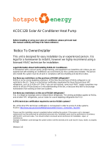
The general performance of the modules is heavily
dependent on the intensity of the incident solar
radiation, as illustrated in Fig.1. Acheiving
maximum performance requires proper
installation, with the modules oriented towards
the South and their surface exposed as
perpendicularly possible to the incident rays of
the sun.
Fig. 1: IV curve at different irradiance
Avoid any shading caused by obstacles in and
around the area of installation as shading can
cause loss of output.
A high ambient temperature and therefore, an
increased operational temperature of the
modules, also contribute to a proportional
reduction in electrical performance.
In order to optimize the production of electical
energy of the modules, and therefore of the
system connected to an electrical grid, it is the
responsibility of the installer to make sure the
modules are positioned as much as possible facing
south, with the tilt angle (β) (inclination of the
surface of the modules in respect to the ground,
as shown in Fig.2) optimal for the type of desired
application.

4
© 2011-2013 Silfab Ontario Inc. - Specifications in this manual are subject to revisions without notice
SAFETY AND INSTALLATION MANUAL FOR
PHOTOVOLTAIC MODULES
Fig. 2: Orientation Vs. Azimuth
The tilt angle of ideal average throughout Ontario,
Canada is β = 30°; however, even the inclination
typical the roof of a dwelling (β = 15-20°), being
already an inclined plane, could make the angle
acceptable, if not ideal, for the installation of
coplanar modules on it (using a special standard
structure for support).
Depending on the variation of the tilt angle of the
modules with respect to the ground, or of their
orientation in relation to facing south (Azimuth),
there will be changes in the annual average
amount of energy produced by the modules
themselves, and therefore, of the plant connected
to the network to which they are linked.
2. Disclaimer of Liability
Since the methods of system design, installation
techniques, handling and use of this product are
beyond company control; SILFAB does not assume
responsibility and expressly disclaims liability, for
loss, damage or expense resulting from improper
installation, handling or use.
3. Underwriters Laboratories (UL)
Listing Information
This product meets or exceeds the requirements
set forth by UL 1703 for PV Modules. This UL
Standard covers flat-plate PV modules and panels
intended for installation on buildings or those
intended to be freestanding. To satisfy the listing
for this product the modules must be mounted
with a rack or standoff structure. The UL listing
does not include integration into a building
surface because additional requirements may
apply. This product is not intended for use where
artificially concentrated sunlight is applied to the
module.
4. Limited Warranty
Please refer to SILFAB General Terms and
Conditions of Sale for details of the modules’
limited warranty. Failure to comply with this
Safety and Installation Manual will invalidate
SILFAB Warranty for the PV modules as stated in
the General Terms and Conditions of Sale.
5. Module Specification
Please refer to the technical datasheet for the
module SILFAB SLA or SLG respectively for
electrical performance data. These electrical data
are measured under Standard Test Conditions
(STC) of 1000 W/m2 irradiance, with Air Mass (AM)
of 1.5 spectrum, and a cell temperature of 25°C.
East
β
South

5
© 2011-2013 Silfab Ontario Inc. - Specifications in this manual are subject to revisions without notice
SAFETY AND INSTALLATION MANUAL FOR
PHOTOVOLTAIC MODULES
6. Safety Precautions
Installation should be performed only by
authorized personnel!
Module installation must be performed in
compliance with the latest U.S. National
Electrical Code (NEC) in the USA or with the
latest Canadian Electrical Code and any
applicable local codes.
Within the modules there are no user
serviceable parts. Do not attempt to repair any
part of the modules. Contact your module
supplier if maintenance is necessary.
In order to reduce the risk of electric shock,
prior to installing the modules, remove
metallic jewelry and use insulated tools during
installation.
Modules produce voltage even when not
connected to an electrical circuit or load and
have no on/off switch. Modules can be
rendered inoperative only by removing them
from sunlight, or by fully covering their front
surface with cloth, cardboard, or other
completely opaque material, or by working
with them face down on a smooth, flat
surface.
Do not expose the modules to artificially
concentrated sunlight!
Do not stand on, drop, scratch, or allow
objects to fall on the modules.
Do not lift the modules at the connectors or
junction box!
Do not install or handle the modules when they
are wet or during periods of high winds.
Do not use oil based lubricants on any part of
the junction box as this can cause long term
damage to the plastics.
Ensure that wire cable connections are routed
in accordance with the junction box
manufacturer’s recommendations. Incorrect
routing of the wire cable can lead to stress
damage to the junction box.
Do not leave cable connectors exposed in
adverse climatic conditions. Water and dust
deposits inside the cable connectors can cause
long term damage.
Broken module glass, a torn backsheet, a
broken junction box or broken connectors are
electrical safety hazards; consequently,
contact with a damaged module can cause
electric shock.
The total voltage of modules connected in
series corresponds to the sum of the voltages
of the single modules; whereas connecting the
modules in parallel results in adding up the
currents. Consequently, strings of inter-
connected modules can produce high voltages
and high currents and constitute an increased
risk of electric shock and may cause injury or
death.
For installation, maintenance, or before
making any electrical connection or
disconnection, ensure all modules in the PV
array are exposed to a light intensity that is
less than 400 W/m2!! Follow the Isc
measurement instructions in section 8b to
determine the value of the solar irradiance
(E).
• Methods to ensure a low solar irradiance
when making electrical connections or
disconnections include:
o Covering the modules with an opaque
cloth or other material in order to
shield them from exposure to light

6
© 2011-2013 Silfab Ontario Inc. - Specifications in this manual are subject to revisions without notice
SAFETY AND INSTALLATION MANUAL FOR
PHOTOVOLTAIC MODULES
intensity greater than 400 W/m2.
Opaque material can be supplied by
Silfab upon request.
o Making the connections during hours of
low intensity of solar irradiance (such
as early morning or late afternoon).
o Making the connections with the
modules tilted perpendicular to the
sun, to increase shading between the
strings thus decreasing solar irradiance.

7
© 2011-2013 Silfab Ontario Inc. - Specifications in this manual are subject to revisions without notice
SAFETY AND INSTALLATION MANUAL FOR
PHOTOVOLTAIC MODULES
7. Installation
7a) Module Mounting
The module is class C fire rated.
When installing Silfab modules, local building
code requirements and regulations must be
adhered to at all times. In particular, in case
of roof mounting, fire protection must be
compatible with the class C fire rating (ie. fire
resistant roofing materials). Class C rating is to
be maintained when mounting the modules at
any inclination angle.
Sufficient ventilation of the module backside is
required for maintain the Class C fires rating,
and therefore the mounting configuration (e.g.
sufficient clearance) should be adapted
accordingly. The recommended clearance
distance is a minimum 10 cm.
Do not drill any additional holes into the
module frames and do not cover the
drainage holes.
Pre-assembled mounting systems will need
written approval by Silfab in advance.
• The modules can be mounted in every angle
from horizontal to vertical, avoiding
configurations with the junction box up-side
down at all times (e.g. trackers with “sleep
mode”).
• In order to maximize module exposure to
direct sunlight, the modules should be
oriented to the south in the northern
hemisphere and to the north in the southern
hemisphere.
Mounting Methods:
Mounting using mounting holes:
• Each module must be securely fastened at
a minimum of 4 points.
• Use the 4 mounting holes (slots, see Fig.
3a/3b) on the PV module frame to bolt the
module with M6 (1/4”) stainless steel
screws and nuts to the mounting
framework.
• The distance of the mounting holes has
been designed in order to result in a
uniform wind and snow load without
damaging the module.
Do not drill additional holes in the
module frame; doing so will void the
Warranty.
Mounting using clamping method:
• Silfab recommends the use of clamps with
a design as shown in Fig. 4a (or
equivalent). The use of improper clamps
will void the Warranty.
• When using clamps, it is possible to mount
the modules in horizontal (the shorter side
of one module facing the shorter side of
the neighboring module) or in vertical (the
longer sides facing each other)
configuration. Refer to Fig. 4b,c,d for an
example of attaching the modules to a
support structure using mounting clamps.
(It is recommended to always use stainless
steel screws and bolts.)
• The modules can be mounted on
continuous base structures (inclined or
horizontal) such as rails or similar.
• Both base structures must be mounted at
the same distance from the symmetrical
axis (vertical or horizontal) of the module
(Fig. 5a/5b).
• In vertical configuration, it is strongly
recommended to place the supporting
elements nearby the mounting holes, or in
any case, allow a spacing of 800-941 mm
between them. This is necessary in order
to maintain a correct load distribution (Fig.

8
© 2011-2013 Silfab Ontario Inc. - Specifications in this manual are subject to revisions without notice
SAFETY AND INSTALLATION MANUAL FOR
PHOTOVOLTAIC MODULES
5a/5b), and achieve the 5.4 kPa load
rating.
• In horizontal configuration, fixing the
modules by blocking them at the 4
mounting holes will guarantee the
characteristics regarding the static loads as
certified.
• When clamping the modules in horizontal
configuration on a support structure, the
following rules have to be applied in order
to maintain the resistance against static
loads as certified:
o If the bars or rails are in vertical
direction, they have to be placed
nearby the corner holes or in any case
a spacing of 800-941 mm between the
bars has to be maintained in order to
achieve the 5.4 kPa load rating (Fig.
5a/5b).
o If the bars or rails are in horizontal
direction, they have to be placed with
a spacing of 500-750 mm in order to
achieve the UL specified 2.4 kPa load
rating (Fig. 5a/5b).
• The modules can also be fixed by placing
them with their frame on a structure that
is supporting the two sides of the frame
over their whole length. In this case, the
position of the mounting clamps must be in
accordance with the above mentioned
spacings (800-941 mm and 500-750 mm
respectively) – refer also to Fig. 5a/5b.
Fig. 3a: Mechanical drawing of an SLA module showing
the mounting holes, the drainage holes, and the
ground connection holes
Fig. 3b: Mechanical drawing of an SLG module showing
the mounting holes, the drainage holes, and the
ground connection holes

9
© 2011-2013 Silfab Ontario Inc. - Specifications in this manual are subject to revisions without notice
SAFETY AND INSTALLATION MANUAL FOR
PHOTOVOLTAIC MODULES
Fig. 4a: cross section of a mounting clamp to be used
for attaching the modules to support structure.
Fig. 4b: modules attached to supporting structure
(rail, item 01) using a clamp (item 02) fixed with a bolt
(item 03) and nut (item 04) – view between two
modules.
Fig. 4c: modules attached to supporting structure –
side view.
Fig. 4d: end of module row with additional spacer
(item 05: 50mm x 30mm x 24mm)
Fig. 5a: allowed positions for fixing SLA modules using
mounting clamps.

10
© 2011-2013 Silfab Ontario Inc. - Specifications in this manual are subject to revisions without notice
SAFETY AND INSTALLATION MANUAL FOR
PHOTOVOLTAIC MODULES
Fig. 5b: allowed positions for fixing SLG modules using
mounting clamps.
7b) Handling of Modules
The Silfab modules are robust, but in
particular the glass front cover and cells may
be subject to damage if the modules is
improperly handled or installed.
Wear protective gloves when handling and
installing the modules in order to be protected
against cutting by sharp edges and against skin
burns.
Handle the module in a way that avoids
breakage or scratching of the front cover glass
and mechanical damage to any other part of
the module.
Do not carry the module by its connector wires
in order to avoid the risk of electric shock and
prevent damage to the module.
During the wiring and installation of the
modules use caution!
Do not trample on or scratch the modules.
Do not drop sharp or heavy objects on either
surfaces of the module.
Do not subject the modules to any impact, in
particular in the vicinity of the edges of the
frames and do not flex them mechanically.
The modules are made of a single laminate,
therefore once damaged, they are not
repairable.
In the event of any damage to either the front
or the back of the module, the part exposed
might be electrically active and therefore
dangerous, especially if the module is
connected in series to a string.
ATTENTION: in the case of installation with
modules in the vertical position, it is
preferable to maintain the Junction Box
located in the upper part of the module. This
practice will help reduce, as much as
possible, contact between any standing
water and the Junction Box, and avoid
possible water infiltration.

11
© 2011-2013 Silfab Ontario Inc. - Specifications in this manual are subject to revisions without notice
SAFETY AND INSTALLATION MANUAL FOR
PHOTOVOLTAIC MODULES
The junction box does not require any extra
field wiring at the terminals. (Changing wires
or modifying any piece of the junction box,
including the bypass diodes will void the
module warranty.)
7c) Electrical Connection
Danger! Risk of serious injury or death from
electric shock or electric arc flash! Do not
connect or disconnect modules under load!
Even if the modules are protected against
accidental contact, under unfavorable
conditions high hazardous voltage (several
hundreds of volts) may occur during
installation. Consequently, installation and
maintenance of the modules, as well as the
connection to the main power supply, may
only be performed by authorized and qualified
persons.
Before connection of the system to the grid,
the PV system must be approved for correct
installation, by an electrician responsible to
the operator and the local electricity
company.
The design of the PV system should be done by
a qualified person familiar with PV system
design. The system design is the responsibility
of the PV system designer. Therefore, SILFAB
does not assume any liability for how the
modules are installed.
The junction boxes used with SLA/SLG modules
contain bypass diodes wired in parallel with
the PV cell strings. In the case of partial
shading, the diodes bypass the current
generated by the non-shaded cells, thereby
limiting the module’s heating and
performance losses. Bypass diodes are not
over-current protection devices.
In the event of a known or suspected diode
failure, installers or maintenance providers
should contact Silfab. Never attempt to open
the junction box by yourself!
Under normal conditions, a PV module is likely to
experience conditions that produce more current
and/or voltage than reported at STC. Accordingly,
the values of Isc and Voc marked on the module
should be multiplied by a factor of 1.25 when
determining component voltage ratings,
conductor current ratings, fuse sizes, and size
of controls connected to the PV output. Refer to
NEC 690.8 (B) for an additional 1.25 multiplier
that may be required for sizing fuses and
conductors.
• Voc should be increased by a factor according
to the lowest ambient air temperatures
expected for the installation site. Refer to NEC
690.7 for the correct Voc correction factor
according to the respective temperatures. If
this information is not available, a 1.25
multiplying factor can be used as default value
for correction of Voc.
• In order to obtain the required electrical
current and/or voltage, the modules can be
connected in series, in parallel, or in a
combination of both.
o In the case of series connection, do not
exceed the maximum system voltage of
600V even at low temperatures. Always use
the same type and rating of module in one
installation!
o In the case of parallel connection of
modules or series strings of modules, fusing
may be required. Information about the
fuse rating can be found on the module’s
nameplate and in the datasheet – see also
NEC 690 for additional fusing requirements.
o The voltage of the strings of modules, in
series, when measured at their poles, is
the sum of all the individual voltages of

12
© 2011-2013 Silfab Ontario Inc. - Specifications in this manual are subject to revisions without notice
SAFETY AND INSTALLATION MANUAL FOR
PHOTOVOLTAIC MODULES
each module. This total voltage should be
compatible with the range of input
voltages admissible for the inverter to
which the modules are connected.
7d) Grounding
• The module frame or array must be grounded
before wiring. For grounding, use material that
is certified according to UL 1703 – in particular
the grounding should be performed by a
qualified electrician using grounding methods
in accordance with article 250 of NEC and
relevant local codes and regulations.
• SLA/SLG modules can be grounded using third
party grounding devices as long as they are
certified for grounding modules and the
devices are installed according to the
manufacturer’s specified instructions.
• Examples of acceptable grounding methods
include the following (must be verified with
local codes and regulations):
o Attach a separate approved ground wire to
one of the holes marked with a ground
label on the module frame with a UL
approved ring terminal or UL listed
grounding lug.
o Schletter Rapid Clamps are acceptable
when using the proper size to match
Silfab’s 38 mm frame.
o WEEB clips compatible with the chosen
racking mounting clip are also acceptable
when properly installed (ensuring an
electrical bond between the module frame
and the grounded racking).
• Ensure that the grounding area for the
connection is clean and free from oxides or
any debris that could impede the electrical
grounding.
Always follow safety procedures when
installing any grounding/mounting system.
7e) Environmental Considerations
• SLA/SLG modules should be installed in a
location where there is no shading throughout
the year.
A module is considered "shadow-free" if it is
unobstructed across its entire surface for the
whole year. Even on the shortest day of the
year, unobstructed sunlight can reach the
module.
Ensure there are no obstacles to block light
near the installation site.
• Lightning protection is recommended for PV
systems that are to be installed in locations
with high probability of lightning strikes.
• Although Silfab modules are designed to be
able to withstand high snow pressure, in
regions with heavy snowfall in winter, select
the height of the mounting system so that the
lowest edge of the modules is not covered by
snow for any length of time.

13
© 2011-2013 Silfab Ontario Inc. - Specifications in this manual are subject to revisions without notice
SAFETY AND INSTALLATION MANUAL FOR
PHOTOVOLTAIC MODULES
8. USE AND MAINTENANCE
8a) Intended Use
SLA/SLG modules are designed for use in grid-
connected systems. They are therefore linked in
series/parallel combinations to feed a dedicated
inverter with a DC input and an AC output of 110V
AC - 60Hz to provide energy to the local
electricity grid.
8b) Operational Measurements
The only two electrical parameters of output from
a PV module, measurable with conventional
instrumentation, are the Voc and Isc.
When the PV modules are instead connected in
series/parallel configuration to an inverter, from
its display it is possible to read:
• Operational voltage at maximum power
output (Vpmax) of the string
• Operational current at maximum power
output (Ipmax) of the string
From these above values it is possible to estimate
the voltage at maximum power (Vpmax) of a
module in the string under review and any non-
uniformity in the voltages (Vpmax) of multiple
strings connected to the same inverter.
From the Ipmax for the string it is also possible to
verify whether there are obvious differences
between one string and another. When a uniform
condition is detected, it can be assumed that all
the modules are working properly.
The following measures serve to collect
preliminary information on the operational status
of the PV modules in a PV system.
If there is a need to perform direct measurements
on individual modules using conventional
instrumentation, the following action should be
taken:
To measure the open circuit voltage (Voc):
• Note: even in the presence of an insolation
average of 500 W/m2, a module exposed to the
rays of the sun presents at its poles (+ and –) a
Voc very close to the nominal value at STC (as
shown in Fig.3).
• When taking the temperature at which the
module is working at that moment into
account, the open circuit voltage module
(Vocmod) will be approximately equal to:
Vocmod = VocSTC – [(Tmod – 25°C) x 0.125V]
Where:
• VocSTC is the open circuit voltage
measured at STC;
• -0,125V/ °C is the average variation of
Voc of a module for a variation in
temperature of 1°C;
• 25°C is the reference temperature of
STC;
• In the case of good solar radiation and
at the ambient temperature (Tamb), one
can estimate the temperature of the
module as follows:
Tmod = Tamb + 30°C
• Using the calculations above, it is possible
when measuring with a multi-meter, to verify
Voc meets the standard shown in the module
datasheet.
• In a case that the Voc to the connectors is
decidedly lower than the standard values (75%
or less) this could represent a condition of
anomaly which should be investigated more
thoroughly.
To measure the short-circuit current (Isc):
• A PV module exposed to the south, inclined
perpendicularly to the rays of the sun, in the
middle of the day (about 12:00 to 1:00 PM )
and in conditions of good weather, presents a
value of Isc similar to the rated values at STC,
as measurable with an amp-meter in
continuous current.
• By measuring the solar radiation (E) effective
at the moment with a solarmeter/pyranometer
in W/m2 the short circuit current of the

14
© 2011-2013 Silfab Ontario Inc. - Specifications in this manual are subject to revisions without notice
SAFETY AND INSTALLATION MANUAL FOR
PHOTOVOLTAIC MODULES
module at the moment Iscmod should be very
close to the following value:
Iscmod = IscSTC x E/1000
Where:
• IscSTC is the short circuit current
measured at STC;
• 1000 W/m2 is the radiation at STC.
• The measurement of the Isc is executable with
precision only when using a
solarmeter/pyranometer which gives exact
information on the conditions of solar
radiation at the moment, otherwise it is not
reliable.
• In the case of the unavailability of a
solarmeter/pyranometer, it will only be
possible to have an estimate of the
functionality of the module by comparing the
value of Iscmod measured in relation to those of
the other modules of the PV system, measured
under the same conditions of irradiation.
The acknowledgment of any obvious
discrepancies of Isc in the modules thus serves
to identify anomalies.
• NOTE: an excess of intensity due to
meteorological phenomena (for example,
lightning) or mistakes in the connection (for
example, connecting the modules under full
irradiance) can cause damage, or short-circuit
of the bypass diodes contained in the junction
box. As a result, the Voc of the module may
decline in proportion to the damaged diodes to
⅔Voc, ⅓Voc, or 0V. In this case, the bypass
diodes must be substituted only by Silfab
personnel, onsite or offsite at Silfab’s sole
discretion.
8c) Maintenance
Although PV modules do not require any routine
maintenance, periodic (annual) inspection for
damage to glass and inspection of the electrical
connections and for corrosion as well as the
mechanical connection is recommended.
Under normal conditions (sufficient rainfall),
cleaning of the module is not required. In extreme
climatic conditions, the electrical performance of
the module may be affected by accumulation of
dirt, dust or debris on the glass front cover.
In this case, the front cover can be washed using
water or commercial glass cleaners, alcohol/
ethanol/methanol and a soft cloth.
Do not use abrasive brushes, powders, cleaners,
polishers, sodium hydroxide, benzene, nitro-
thinners, acid or alkali and other chemical
substances. Doing so may damage the anti-
reflective coating that is present on the glass of
some Silfab modules.
Most municipal water used as cleaning water;
however, it is not recommended to use water with
high mineral content as it may deposit on the glass
surface when the water is dry. The pressure of the
cleaning water should be less than 690Kpa.
Exercise extreme caution when applying water
on any electrical device!!
The module cleaning should be done in the early
morning, in the evening, at night or on rainy days.
When cleaning in the morning or evening,
select the period when sunshine is not strong.
If you need to clear snow to improve output
power, use a soft brush to gently remove the
snow. But do not try to remove frozen snow or ice
on the modules as it could lead to property
damage.
ATTENTION!!!!!:
To avoid the phenomena of electric arcing, both
the connection and disconnection of the
connectors of the modules being tested and the
measurements of Voc and Isc should be performed
with the string of modules in conditions of open
circuit.
In addition, the Isc should be measured for each
individual module in conditions of open circuit
and not to the extreme poles of the string, which
could be affected by voltages up to 600V.

15
© 2011-2013 Silfab Ontario Inc. - Specifications in this manual are subject to revisions without notice
SAFETY AND INSTALLATION MANUAL FOR
PHOTOVOLTAIC MODULES
9. PACKAGING, HANDLING AND
STORAGE OF MODULES
9a) Silfab's Packaging
SILFAB Ontario provides the SLA/SLG modules in
the most appropriate packaging, designed to
guarantee that the transportation and storage will
be in conditions of maximum safety and protection
until the time of installation. Each package
contains up to 35 modules, arranged in a
horizontal position with the glass facing
downwards (as shown in Fig. 6).
Transport the module in its original packaging
until installation. If transporting outside of the
original packaging is necessary, contact Silfab for
written approval in advance.
Protect all parts of the module during transport
and installation from mechanical stresses.
Fig. 6: Module Packaging
The packaging consists of:
• A maximum number of 35 SLA modules or
30 SLG modules
• 1 wooden pallet (Fig. 7)
• 4 plastic protective corner angles per
module (Max 140, Fig. 8)
• Containment straps
• 1 waterproof cover
• Transparent film for containment
Fig. 7: Wooden pallet Fig. 8: Protective corner
9b) How to Manage the Packaging
Each package has been designed to allow the
shipment and storage of modules in order to
maintain their integrity unchanged over time,
provided that the information and indications
supplied by SILFAB Ontario are closely observed
and followed. These indications are summarised
by a series of standard symbols posted in a visible
manner on each pallet. The list below illustrates
the meaning of each symbol:
DO NOT STACK: each pallet of modules is
packaged according to the maximum number of
modules stackable vertically, in order to avoid or
reduce mechanical stress or damage as a result of
the pressure exerted by the stacked modules.
Therefore, it is absolutely forbidden to stack a
pallet on top of another, both in the process of
shipment and storage of modules.
DO NOT EXPOSE TO ATMOSPHERIC AGENTS: each
pallet of modules is suitably dressed in a cap of
transparent plastic in order to avoid temporary
contact with generic water spray or atmospheric
agents. The plastic casing does not ensure the
protection of the modules in the case of prolonged
exposure to atmospheric agents. Similarly, in the
case of flooding, the pallet does not ensure the
maintenance of the mechanical properties of the
weight of the modules. For this reason it is
recommended to store the pallet in a place that is
sheltered and dry. In addition, as the the junction

16
© 2011-2013 Silfab Ontario Inc. - Specifications in this manual are subject to revisions without notice
SAFETY AND INSTALLATION MANUAL FOR
PHOTOVOLTAIC MODULES
box has an IP65 degree of protection, in the event
of a flood the stagnant water inside of the frame
could oxidise the metal contacts of the connectors
degrading the characteristics and altering the
electrical properties of the contacts of the module
causing damage.
DO NOT OVERTURN THE PACKAGING: the
packaging is only designed to be handled and
stored with the modules maintaining the position
of the arrow printed on the packaging, with the
arrow always facing upwards. Not following these
indicated directions may create forms of
mechanical stress on the modules that could cause
damage or breakage.
RECYCLABLE: most of the photovoltaic modules
are recyclable. They should not be thrown into
landfill without a proper method for recycling.
Although they are not yet regulated by current
rules of refutes RAEE, many institutions and public
structures are organising to collect the modules
that are damaged or are no longer usable for
materials.
FRAGILE: the photovoltaic modules are
manufactured using a glass front which makes up
approximately 70% of the total materials used to
construct them. Although the modules are
stiffened by an aluminium frame, any direct
impact to the glass or on the corners of the
modules should be avoided. Avoid flexing the
laminates or applying non-distributed loads and
stresses. Avoid scratching the surface of the
exterior glass or backsheet. Do not apply any
forces to the backsheets.
HANDLE WITH CARE: during the operation of
shipping and storage of the modules use maximum
care to ensure the full integrity of the modules.
9c) How to Handle the Pallet
During the handling of the pallet make sure to pay
the utmost attention. The packaging must be
raised/moved exclusively with fork-lift trucks or
hand pallet trucks fitted with forks of length
appropriate to its size and weight. The pallet
which supports the packaging is a "4 ways" type,
(able to be lifted from any of the short or long
sides) with dimensions of 1750 x 1080 mm. For the
safe handling of the pallet the forks length should
be:
• A minimum of 1800 mm for lifting from the
shorter side
• Able to support the total weight of the
packaging of approximately 700 kg
Fig. 9: How to handle the packaging
Pay attention during the stages of handling and
unpacking. Verify that the package is positioned
on a surface that is either flat or not excessively
deformed to a point that would impart an
1800 mm minimum fork
length
When using a forklift, please
ensure the forks go all the
way through pallet

17
© 2011-2013 Silfab Ontario Inc. - Specifications in this manual are subject to revisions without notice
SAFETY AND INSTALLATION MANUAL FOR
PHOTOVOLTAIC MODULES
inclination to the pallets which could damage the
PV modules.
SILFAB DOES NOT ASSUME RESPONSIBILITY IN THE
EVENT OF DAMAGE TO THE MODULES ARISING
FROM MANAGEMENT OF THE PACKAGING THAT IS
IMPROPER OR DIFFERENT FROM WHAT WAS STATED
IN THIS DOCUMENT.
9d) Unpackaging
Observe the following procedures for the
unpacking of modules:
• Place the packaging on a stable and flat
surface
• Using a cutter, cut the plastic wrap
surrounding the package
• Remove the plastic wrap
• Remove the upper cover
• Recover the flash list (for record keeping)
• Using a cutter, cut the straps
• Remove the PV modules and their
protective corners without damaging
• Collect and store the protective corners
and the wooden pallets awaiting recovery
by the supplier, as described in section 9f.
Note: avoid storing partial packaging!
Once you have removed the strapping the
packaging must no longer be moved!!
9e) Pallet Sheet
Each package has a sheet (“pallet sheet”) placed
in a visible position and containing some pertinent
information such as: serial number of each
module, part number of each module and pallet
number. All Numbers are readable with a standard
bar code reader. See Fig.10 below.
Fig. 10: Pallet sheet
9f) Recycling Packaging Materials
SILFAB undertakes efforts to treat every aspect of
production, to minimize the environmental
impact. The packaging is made with materials that
for the most part are reusable.
In particular, the wooden pallets (Fig.7) and
protective corners (Fig.8) are to be preserved and
returned intact to the supplier.
SILFAB is a part of the recovery and organizes the
return of these materials. Pallets and protective
corners that are recovered will be reused by
SILFAB on new packages, minimizing the amount
of material ending up in landfills.
The customer must collect the protective corners
in nylon bags or something of similar texture (see
Fig.11), and stack the pallets (max 15 units, see
Fig.12) in order to facilitate the loading
operations. SILFAB will periodically, when the
amount justifies the cost of the transportation,
recover these materials, returning them for reuse
at the manufacturing plant.
Fig. 11 & 12: How to package the pallets and plastic corners,
respectively, after unloading, ready to deliver back to Silfab
for reuse.

Document Number: MAN-SFO-02 Revision Date: April 2, 2013
SAFETY AND INSTALLATION MANUAL FOR
PHOTOVOLTAIC MODULES
10. APPENDIX 1 – Electrical Specifications
SLA250M
SLA255M
SLA260M
SLA265M
SLA270M
SLA275M
SLA280M
SLA285M
Pmax
250
255
260
265
270
275
280
285
Vmp
30.4
30.6
30.8
31
31.2
31.4
31.7
32
Imp
8.27
8.38
8.49
8.6
8.71
8.8
8.86
8.91
Voc
37.4
37.6
37.8
38
38.2
38.4
38.7
39.1
Isc
8.8
8.92
9.04
9.16
9.28
9.36
9.43
9.47
Eff
15.3%
15.6%
15.9%
16.2%
16.5%
16.8%
17.1%
17.4%
SLA240P
SLA245P
SLA250P
SLA255P
SLA260P
Pmax
240
245
250
255
260
Vmp
30.1
30.3
30.5
30.7
30.9
Imp
8.01
8.13
8.24
8.35
8.46
Voc
37.1
37.3
37.5
37.7
37.9
Isc
8.53
8.64
8.76
8.87
8.99
Eff
14.7%
15.0%
15.3%
15.6%
15.9%
SLG300M
SLG305M
SLG310M
SLG315M
SLG320M
SLG325M
SLG330M
SLG335M
Pmax
300
305
310
315
320
325
340
345
Vmp
36.5
36.7
36.9
37.1
37.3
37.5
37.8
38.1
Imp
8.26
8.35
8.44
8.53
8.62
8.7
8.75
8.8
Voc
44.9
45.1
45.3
45.5
45.6
45.8
46.1
46.4
Isc
8.79
8.88
8.99
9.09
9.19
9.29
9.34
9.38
Eff
15.4%
15.6%
15.9%
16.2%
16.4%
16.7%
17.4%
17.7%
SLG290P
SLG295P
SLG300P
SLG305P
SLG310P
Pmax
290
295
300
305
310
Vmp
36.3
36.5
36.7
36.9
37.1
Imp
8.03
8.12
8.21
8.3
8.39
Voc
44.9
45.1
45.3
45.5
45.7
Isc
8.52
8.62
8.72
8.82
8.9
Eff
14.9%
15.1%
15.4%
15.6%
15.9%
Standard Test Conditions (Measurement conditions: STC 1000 W/m² - AM 1.5 - Temperature 25 °C)
Measurement uncertainty ≤ 3% - Sun simulator calibration with modules calibrated by Fraunhofer Institute
Power Tolerance: Positive Sorting (-0/+5W)
Maximum System Voltage: 600V or 1000V (on request)
Series fuse rating: 15A
Electrical characteristics may vary by ±5% and power by -0/+5W

Document Number: MAN-SFO-02 Revision Date: April 2, 2013
SAFETY AND INSTALLATION MANUAL FOR
PHOTOVOLTAIC MODULES
Please conserve a copy of this manual
at the location of the PV System,
and inform the system owner of all relevant aspects of
safety, operation, and maintenance!!
To download a copy of this installation manual scan the QR-Code on the back of a Silfab module,
or go to: www.silfab.ca/media-center/download-area.html
Silfab Ontario
240 Courtneypark Drive East,
Mississauga, Ontario, Canada L5T 2Y3
- Tel: +1 905 255 2501
- Fax: +1 905 696 0267
- Email: info@silfab.ca
- Web: www.silfab.ca
a Company of Silfab Group
Via Trieste 33, 35121 Padova, Italy
- Tel.: +39 (0)49 9431374
- Fax: +39 (0)49 9439735
- -E-mail: info@silfab.eu
- Web: www.silfab.eu
/