Page is loading ...

INTERNATIONAL®
710
MOLDBOARD PLOW
(Semi-Mounted Type
4, 5/6 and 6Furrow)
SETTING UP INSTRUCTIONS
OPERATOR'S MANUAL
_

To The Owner
Your new International Harvester plow
is designed to meet today's exacting operat-
ing requirements. The ease of operation,
and ability to adjust to field conditions
lighten your work and shorten your hours
on the job.
You are urged to consult your
International Harvester dealer concerning
unusual conditions or special applications.
Let the experience of your dealer and the
organization associated with him serve you.
Be sure to read the instructions for Ad-
justing and Operating in this manual. Check
each item referred to and acquaint yourself
with the adjustments required to obtain effi-
cient operation and maximum trouble-free
service. Remember, aplow which is prop-
erly lubricated and adjusted saves time,
labor, and fuel.
After the operating season, thoroughly
clean your plow and inspect it. Preventive
maintenance pays dividends. Your dealer
has original-equipment parts which assure
proper fit and best performance. He is able
to recondition your equipment to alike new
condition.
Your plow will be used intermittently
during the year. Rust and corrosion must be
prevented the year around. Asmall amount
of time and effort spent protecting it from
destructive moisture will repay you many
times in long years of service, easy opera-
tion, and high resale value. Of equal impor-
tance at the end of the operating period are
the care of unprotected surfaces and pro-
vision for suitable waterproof shelter.
Additional copies of this manual may be
ordered from your International Harvester
dealer at anominal price.
CONTENTS
INTRODUCTION
ADJUSTING AND OPERATING
TRACTOR PREPARATION
PLOW PREPARATION
TRACTOR OPERATION
PLOW OPERATION
SETTING UP
OPTIONAL EQUIPMENT
LUBRICATION
SPECIFICATIONS
2
3to23
3
6
7
10
24 to 35
36,37
38 to 42
43

WORK SAFELY-FOLLOW THESE RULES
ACAREFUL OPERATOR IS THE BEST INSURANCE AGAINST AN ACCIDENT.
AThis symbol is used to call your attention to instructions
concerning your personal safety. Be sure to observe and
follow these instructions.
BEFORE OPERATING
Do not wear loose-fitting clothing which
may catch in moving parts.
Use extreme care when making adjust-
ments.
When working under or around the plow,
always support the plow frame.
After servicing, be sure all tools, parts,
or servicing equipment are removed from
the machine.
Make sure that there is no one near the
machine before operating.
and lines are in good condition before apply-
ing pressure to the system. Relieve all pres-
sure before disconnecting the lines or per-
forming other work on the hydraulic system.
To find aleak under pressure use asmall
piece of cardboard or wood: Never use hands.
Do not attempt to remove any obstruc-
tions while the plow is in motion.
Keep hands, feet, clothing and objects
away from moving parts.
Do not ride on the plow during operation.
Use extreme care when operating close
to ditches, fences, or on hillsides.
DURING OPERATION
No one other than the operator should
ride on the tractor.
Hydraulic fluid escaping under pressure
can have enough force to penetrate the skin.
Hydraulic fluid may also infect aminor cut
or opening in the skin. If injured by escap-
ing fluid, see a doctor at once. Serious in-
fection or reaction can result if medical
treatment is not given immediately. Make
sure all connections are tight and that hoses
ON-HIGHWAY OPERATION
Always place the machine in the trans-
port position.
Comply with your state and local laws
governing highway safety, and with regula-
tions when moving machinery on ahighway.
Drive at areasonable speed to maintain
complete control of the machine at all times.

INTRODUCTION
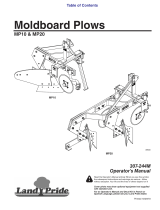
M433I54
lllust. 2
710 Moldboard Plow (six-furrow) shown.
ACAUTION: WHEN TRANSPORTING OR IN THE FIELD, SLOW DOWN
BEFORE TURNING. Do not use individual tractor wheel braking to make
short turns. This plow has limit stops which do not permit pivot turns.
ruwSaJe
INSIST ON IH PARTS
WHEN you bought your International Harvester tractor
or machine, you made agood choice—you have amachine
that deserves good care and good service. When wear
and tear make new parts necessary, remember why you
bought an International Harvester Quality Product. You
bought quality to be sure of performance. Don't handicap
your equipment by careless selection of replacement parts.
PLAY SAFE! Go to the International Harvester
dealer for IH parts. The IH trademark is your
guarantee of quality, your best assurance that your
International Harvester equipment will continue to give
you top-grade performance, no matter what you ask of it.

ADJUSTING AND OPERATING
TRACTOR PREPARATION
TRACTOR STABILITY
THREE-POINT HITCH ADJUSTMENT
Refer to the Operator's manual furnished
with the tractor and add weight as shown
therein and in the amounts specified be-
low:
Farmall and International Tractors:
Add 1000 to 1200 pounds of front end weight,
depending on the capacity of the tractor
front end weight mounting bracket being
used.
Tractors Of Other Manufacture: Add
sufficient front end weight to assure sta-
bility.
TRACTOR WHEEL WEIGHT
It is recommended that the tractor rear
wheels carry added weight for increased
traction. Adding weight saves wear on the
tires and also serves to stabilize the trac-
tor for plowing on rough or hillside fields.
For this purpose, liquid such as calcium
chloride solution can be placed in the rear
tires, or one or two weight (available from
your International Harvester dealer) may
be bolted on each rear wheel. In loose soil
it may be necessary to use both the liquid
and the weights to prevent excessive tire
slippage
.
A84610
lllust. 3
Turn the eyebolts "A" with the offset
toward the tractor.
Locate the lock-out pins "B" in the holes
in the lateral limiter links as shown.
Note: For easy attaching and detaching
temporarily remove the pins "B".
Locate the lift link lock-out collars "C"
in the upper position as shown. Turn the set
screw into the upper spot hole in the link.
Use either or both leveling cranks "D"
to level the hitch with the ground. The hitch
bail is level with the tractor axle when the
grooved lines show just above the screw
housings at "E".
Be sure to move the swinging drawbar
forward to the storage position as shown
at "G".
/
/
_

ADJUSTING AND OPERATING
TRACTOR PREPARATION -Continued
TWO-POINT HITCH ADJUSTMENT
A-747B8
lust. 4
Locate the lock-out pins "A" in the holes
as shown to keep the sockets rigid with the
hitch bail.
Use either or both leveling cranks "D"
to level the plow with the ground. The hitch
bail is level with the tractor axle when the
grooved lines "E" shown just above the
screw housings. Level the hitch bail with
the tractor axle for opening up.
QUICK-ATTACHABLE COUPLER
(See tractor manual)
Operate with upper link as short as
possible.
TIRE INFLATION
The use of the proper air pressure is
the most important factor in satisfactory
performance and maintenance of tractor
implement tires. Underinflation will dam-
age the cord body of the tire and cause a
series of diagonal breaks in the fabric in
the sidewall area. If the tire buckles or
wrinkles, the air pressure should be in-
creased to the point where the sidewalls
remain smooth while operating.
Set the lateral limiter blocks "B" as
shown to control the side-to- side motion of
the hitch bail.
Check the air pressure every two or
three weeks and do not allow the pressure
to drop below the recommended pressures:
Locate the lift link lock-out collars "C"
in the upper position as shown. Turn the set
screw into the upper spot hole in the link.
Tractor tires .See your Tractor
Operator's Manual

ADJUSTING AND OPERATING
TRACTOR PREPARATION -Continued
TRACTOR REAR WHEEL SETTINGS
Single Wheels
In-The-Furrow Operation
Measure from the center of the power
take-off shaft to the inside edge of the right
rear tire and set it at 30-inches or 32-inches
as desired. The left wheel should be set
the same. However, when it is desired to
give the tractor greater stability, such as
hillside plowing, the left wheel may be set
slightly wider.
Single Wheels'
On-The-Land Operation
Measure from the center of the power
take-off shaft to the inside edge of the right
rear tire and set it at 30-inches or 32-inches
as desired. The left wheel should be set
the same. However, when it is desired to
give the tractor greater stability, such as
hillside plowing, the left wheel may be set
slightly wider.
Dual Wheels
On-The-Land Operation
The recommended overall tractor rear
tire width to be used with plows equipped to
operate "on-the-land" is 123 inches, and
better performance can generally be ob-
tained with narrower settings. Illust. 5
shows the recommended wheel settings.
These settings can be obtained when the
outside (dual) wheel has an offset of not
more than 5-1/2 inches. When plowing with
dual wheels and the tractor is equipped with
acab, it may be necessary to move the
right, inside tire closer to the cab than the
recommended 4-1/2 inches as outlined in
the Tractor Operator's Manual. The left
wheels may be set out to allow clearance
between the inside tire and the door of the
cab.
61.5 inches maximum Irom center of tractor -
2-5/8
inches
2-3/4
inches
Hub clamps lb clamps =iP
Hub clamps A-S4604
Illust. 5
Mounting diagram for removable disc-type
dual wheels.
The maximum overall tractor rear tire
width to be used with plows equipped to
operate "on-the-land" is 133-inches, and
better performance can generally be ob-
tained with narrower settings. See tractor
operator's manual.
When operating in extremely dif-
ficult soil conditions, it is advantageous to
have as narrow arear wheel setting as is
safely possible.

ADJUSTING AND OPERATING
PLOW PREPARATION TRANSPORTING ON THE HIGHWAY
GENERAL
Tighten bolts and screws: When Starting to
plow with anew plow or one which has been
stored, check to see that all bolts and set
screws are tight and that all cotters are
spread to keep them from falling out. It is
especially important that the bolts holding
the plow bottoms be drawn up very tight.
REMOVING PROTECTIVE COATING FROM BOTTOMS
The bracket and socket for aslow moving
vehicle (S.M. V. )emblem must be attached
as near to the rear and center of the vehicle
as practicable. The slow moving vehicle
emblem must be in aplane perpendicular to
the direction of travel (plus or minus 10
degrees) and be placed centrally at the rear
of the vehicle, unobscured and two to six
feet above the ground measured from the
lower edge of the emblem. See lllust. 6.
Plow bottoms are highly polished and
coated to prevent rusting before leaving the
factory. Good work cannot be accomplished
until this coating is removed.
The S.M. V. emblem should be used at
all times while on apublic road.
The black, protective coating on the
bottoms will quickly wear away in most
soils; however, for soils which scour with
difficulty, it is advisable to remove the
coating before attempting to plow. For this
purpose, use gasoline, kerosene or diesel
fuel.
ACaution! Do not permit smoking, sparks or an
open flame where combustible fuels are being
used to remove the protective coating. Keep
the work area well ventilated.
If the plow is not used immediately scrape
off the dirt, clean and protect the polished
surface of the bottoms with aliberal coat-
ing of heavy grease.
TIRE INFLATION
Gauge Wheel tire 30 pounds
Rear furrow wheel tire 40 pounds
PARKING STAND
Before lowering the plow for detaching,
swing the stand down and secure it with
handle. See lllusts. 24A and 29.
For operation, swing the stand up along
the pull beam and secure with handle.
Comply with all state and local laws gov
erning highway safety and with any regu-
lations which cover moving machinery on
the highway.
Drive at areasonable speed to maintain
complete control of the machine at all times.
s. m. v.
emblem socket
Reflective tape (amber)
(facing forward)
Reflective tape (red)
(Facing rearward)
A-S6676C
lust. 6
Slow moving vehicle (SMV) emblem,
socket and bracket.

ADJUSTING AND OPERATING
TRACTOR OPERATION
TRACTOR HITCH CONTROL LEVERS
Two-Point and Three-Point Hitches
Farmall and International Tractors
The Two-Point and Three-Point Hitches
are controlled by the levers located at the
right of the operator's seat. See II lust. 7.
1. Inside Control Lever (Position Control)
This lever is used to raise and lower the
hitch and to level the plow. (When beginning
to operate in the field, place the outside
draft control lever in the extreme forward
position). See lllust. 7.
In-The-Furrow Operation
The location of the inside lever in the
quadrant indicates the relative plowing
depth obtained. When the lever is placed
just before the offset near the front end of
the quadrant, maximum depth is obtained.
As the lever is moved toward the "RAISE"
position, shallower depths will be obtained.
Use this lever to establish the desired work-
ing depth in the field. See lllust. 7.
The adjusting stop may be set to help
locate the lever setting. It can then also be
by -passed when needed (as for quick entry
into the ground).
lust. 7
2. Draft Control
(Not recommended for on the land operation)
Draft control is that function of the trac-
tor hitch which responds to variations in
draft and does it quick enough to maintain
anearly constant load on the tractor. When
the load on the hitch increases, the hitch
responds by shallowing the front end of the
plow, which transfers increased weight to
the tractor, thus increasing traction. A
choice of two methods of employing "Draft
Control" is available as follows.

ADJUSTING AND OPERATING
TRACTOR OPERATION -Continued
HITCH CONTROL LEVERS
draft control advantages, plus sets adepth
limit (so that the plow will not go too deep
where lighter soils are encountered).
2A. Draft Control-Modified
(Recommended for In-The-Furrow Operation)
When the plow is properly leveled with
the hitch and with the gauge wheel (as ex-
plained under "Inside Control Lever" sec-
tion) it may be desirable to operate using
"Draft Control-Modified".
This is particularly useful in fields with
extreme soil variations, providing all the
In these cases abottom (or depth) limit
is established by setting the inside lever
while plowing in the lighter soil in the field, (as
instructed under Inside Control Lever).
Next set the outside draft control lever
to establish the desired load for operating in
the heavier soil in the field. The operator can
determine in ashort time the best settings.
See lllust. 8.
A-B4199B
lllust. 8
Draft Control-Modified.
lllust. 8A
Draft Control.
lllust. 8B
Draft Control.
-

ADJUSTING AND OPERATING
TRACTOR OPERATION -Continued
HITCH CONTROL LEVERS -Continued
Draft Control
(Optional for In-The-Furrow Operation)
When strictly draft control is desired,
the inside control lever should be placed
near the front of the quadrant. See 11lust. 8A.
The plowing depth of the front of the plow
is then established by moving the outside
draft control lever from "LIGHT" to
"HEAVY" until the desired depth is attained.
On-The-Land-Operation
Use the inside control lever to help level
the plow while operating in the field. As a
starting point run the lower link hitch pins
about 17" above the ground. (Draft control
is not recommended. Place outside lever in
an extreme forward position).
The adjusting stop may be set to help
locate the lever setting. It can then also be
by-passed when needed (as for quick entry
into the ground).
ACaution! Move the Draft Control lever forward
as far as possible when the plow is discon-
nected.
The speed of hitch response to changing
draft loads can be varied by moving the in-
side control lever past the offset, into the
portion of the quadrant marked "RUN".
When the lever is in the extreme forward
position load sensing is slow. When the
lever is located just beyond the offset in the
quadrant, load sensing is fast. See lllust. 8B.
Any lever setting between the two extremes
may be used depending on field conditions.
When lowering the plow to start plowing,
the inside lever should not be moved directly
to the extreme forward position as this will
cause slow entry of the front of the plow and
also cause the rear cylinder to lower the
rear of the plow too slow.
ACAUTION! Move the outside draft control
lever forward as far as possible when the
plow is disconnected.
Note: Refer to your tractor operator's
manual for more detailed data.
'
v.
/Maximum

ADJUSTING AND OPERATING
PLOW OPERATION
ATTACHING TO TRACTOR
Slip the lower link ball joints over the
plow hitch pins and lock in place with Klik
Pin provided.
Note: Use shields (located in tractor tool
box) ahead of Klik Pins to prevent the Klik
Pins from being dislodged from plow hitch
pins.
The upper link of the tractor is not used.
Secure in the storage position and be sure
it will not interfere with the operation of
the lower links.
When transporting, or in the field, slow
down before turning. Do not use individual
tractor wheel braking to make short turns.
This plow has limit stops which do not per-
mit pivot turns.
SCOURING
If the plow bottoms do not scour im-
mediately, it is because the soil is rather
sticky and you will have to wait until the
bottoms have taken aland polish. This may
require afew rounds or, in very sticky soil,
afew days. To obtain this land polish, it is
recommended that you run the plow rather
shallow and fast. It is also advisable to set
the colters far to the outside of the landside
and not too deep. Sometimes it is necessary
to remove the colters entirely so as to ob-
tain the maximum pressure on the plow
bottom which aids in scouring.
REAR FURROW WHEEL
The purpose of the rear furrow wheel
is to take part of the thrust of the landside
against the furrow wall and to carry the
rear end of the plow when transporting.
The adjustments provided are especially
important when plowing hard or difficult
soils. Make certain the tire is inflated to
the recommended 40 pounds of air pres-
sure before making adjustments.
The bolt "K" in II lust. 10 serves to locate
the axle in one of five possible positions
in the axle sleeve. Use the center position
for average conditions. Note: With the use
of larger tires this adjustment is limited
by tire clearance and care should be taken
not to allow the tire to rub on the linkage.
Adjusting the wheel closer to the furrow wall can aid
in taking side thrust and help reduce landside wear.
Be sure to completely collapse the h/draulic
cylinder each time the plow is lowered to operate.
lust. 10
10

PLOW OPERATION -Continued
REAR FURROW WHEEL -Continued
ADJUSTING AND OPERATING
Lead adjustment: Turn the threaded eyebolt
"L", (lllust. 10) in or out of the rear steering
pipe until the proper measurement is ob-
tained for the plow. Measure from the end
of the pipe to the center of the pivot bolt 6
inches for 16 inch plows or 8inches for 18
inch plows. Secure the setting with the jam
nut. Note that these are starting lengths
which are subject to later adjustment such
as may be indicated by field performance.
The wheel should lead or angle slightly
towards the plowed ground.
VERTICAL ADJUSTMENT
Plow without Gauge Wheel: Turn the cap
screw TT J" (lllust. 10)out to place more of the
weight of the rear end of the plow on the
rear wheel. The adjustment is correct when
the heel of the landside runs about 5/8 -inch
above the bottom of the furrow. While op-
erating, check to see that the rear wheel
link is bearing against the cap screw head.
This indicates that the weight of the plow
is on the rear wheel. After making the
adjustment, lock the cap screw "J" with
the jam nut to secure the setting.
Plow With Gauge WheeLTurn the cap screw
"J"(lllust. 10) all the way in to the head and
lock it with the jam nut. This will allow
maximum upward float of the rear furrow
wheel to allow quicker penetration of the
rear bottom.
It may be desirable to adjust the cap
screw out as instructed in "Plow Without
Gauge Wheel" section.
A. )Where additional soil floatation is
needed.
B. )To help take side thrust if rear of
the plow is overcutting.
If-2-ZQ
MA 51854
lllust. 11
11

ADJUSTING AND OPERATING
PLOW OPERATION -Continued
GAUGE WHEEL
To set the gauge wheel for plowing depth
move the gauge wheel standard up or down
as required and secure it with the retaining
Jpin and Q. A. cotter pin as shown at "Q",
in lllust. 11.
Afull adjustment (approximately 1-1/4-
inches) can be made by moving the standard
either up or down one hole within the
bracket. See lllust. 11, inset at "Q".
Ahalf adjustment (approximately 5/8-
inches) can be made by moving the Jpin and
placing it below the bracket as shown in
lllust. 11, inset at S.
Note: Always install the standard retain-
ing pin at "Q" downward as shown in inset
lllust. 11.
Agauge wheel adjusting tool (optional)
is available for easy gauge wheel adjust-
ment. Use the tool to move the gauge wheel
up or down as shown at "R", lllust. 11.
When making achange in plowing depth
it is necessary to consider the depth control
setting along with the gauge wheel.
FRONT FURROW WHEEL
(For On The Land Operation)
The front furrow wheel should be adjusted
to run in the furrow approximately level
with the front bottom. See lllust. 12. The
depth of the front of the plow is controlled
by this wheel through the front hydraulic
cylinder. After the proper setting is deter-
mined in the field this setting can be main-
tained by using the hydraulic cylinder stop.
See lllust. 12. Athumb screw, lllust. 29 is
supplied with the plow to ease adjusting the
cylinder stop.
lllust. 12
12

PLOW OPERATION -Continued
IN-THE-FURROW OPERATION
ADJUSTING AND OPERATING
Horizontal Hitch Adjustment
Three-Point Hitch
HEU MA-1527 C
1-Hitch pins, Lower Position (tighten to
360 foot-pounds)
2-Reversible cross bar
3-Width of cut setting. See table of cross
bar settings
7-Crossbar bolts (Re-tlghten to 250 foot-
pounds)
lllust. 13
Parts Set for Average Plowing.
Crossbar Settings (See 3in lllust. 13)
Plow size

ADJUSTING AND OPERATING
PLOW OPERATION -Continued
IN-THE-FURROW OPERATION -Continued
Horizontal Hitch Adjustment -Continued
Width of Cut
Set the crossbar to appropriate dimen-
sion. See crossbar setting charts on page 13.
Note: The dimensions given in charts on
page 10 are for average conditions but note
that change may be required because of
variable factors such as soil conditions,
plowing depth or tractor wheel tread. In any
case, see that the front bottom cuts the
proper width.
Overcutting by Front Bottom: Move the cross-
bar toward the left (away from the furrow)
the same amount as the front bottom is
overcutting.
Undercutting by Front Bottom: Move the cross-
bar toward the right (toward the furrow) the
same amount as the front bottom is under-
cutting.
Front Spreader Plate Location
MA 1531 £
lust. 14 -Four Furrow Plow.
MA-3322 A
Mlust. 14A -Five Furrow Plow.
Front of Tractor Pull Toward Furrow
Remove the two (2) bolts from the mount-
ing clip. Move the pull beam to the left ap-
proximately 1.4 inches. Bolt the mounting
clip to the spreader plate using holes "A".
See lllust. 14A for the 5-furrow plows and
lllust. 14B for the 6-furrow plows. Move
the crossbar approximately 2inches to the
right.
Be sure the tie rod is kept taut and is
re -tightened after making adjustment.
1-Spreader plate
2-Spacer

ADJUSTING AND OPERATING
PLOW OPERATION -Continued
IN-THE-FURROW OPERATION -Continued
Horizontal Hitch Adjustment -Continued
Plow Overcuts (tails to the left)
First check the following:
1. Plow is level and front bottom is not
running too deep.
2. Front bottom is not overcutting.
3. Plow is equipped with proper land-
sides and are not worn too badly (wide
landside on rear).
4. Rear furrow wheel has the proper
lead adjustment (slight lead toward plowed
ground)
.
5. Rear furrow wheel is adjusted to run
closer to the furrow wall to help take some
side thrust. (Utilize screw "J" (lllust. 10)
to get down pressure on wheel).
6. Hitch is set properly as instructed.
If all the above is checked and over-
cutting is still aproblem, do as follows:
Move the pull beam to the right (one
position). Note: This will require an adjust-
ment of crossbar or achange in tractor
wheel tread.
Vertical Hitch Adjustment
Crossbar hitch pins should be installed in
the lower holes for normal operation.
Front of Plow Runs Shallow
Locate the hitch pins in the crossbar in
the upper holes. This will have the tendency
to raise the rear of the plow and lower the
front of the plow into the ground.
This change also tends to put more weight
on the rear of the tractor.
Rear of Plow Runs Shallow
When the rear of the plow runs shallow it
may be necessary to lower the hitch pins in
order to get depth at the rear of the plow. To
accomplish this the plow is equipped with a
reversible crossbar. The crossbar is re-
versed by removing it from the pivot post
plates and reinstalling it (top side down).
For an extreme lower setting, reinstall pins
in the lower holes.
Note: When making achange in plowing
depth it is necessary to consider the rear
wheel setting along with the hitch depth set-
ting. The rear wheel should carry appreci-
able weight; however, if it makes adeep
track in the ground and the plowing depth
is satisfactory, then the hitch setting should
be raised slightly. The hitch setting will
determine the plowing depth while the rear
wheel serves to stabilize the selected depth
and keep the plow frame level with the
ground.
15

*
ADJUSTING AND OPERATING
PLOW OPERATION -Continued
ON-THE-LAND OPERATION
Vertical Hitch Adjustment
Crossbar hitch pins should be installed
in the lower holes for normal operation.
Front of Plow Runs Shallow
Locate the hitch pins in the crossbar
in the upper holes. (This will have the tend-
ency to raise the rear of the plow and lower
the front of the plow into the ground)
.
This change also tends to put more
weight on the rear of the tractor.
Horizontal Hitch Adjustment
Front of Tractor Pulls Toward Furrow
Make one of two corrections:
1. Move crossbar to the right (one set-
ting). Note: If the crossbar is set in the (A)
setting it can be moved to the right by in-
verting it. Remove crossbar and install it
top side down. (Do not forget to reverse
the hitch pins to the proper vertical setting),
2. Move the pull beam to the left (one
position) and move the crossbar to the right
(one setting) by following instructions above.
(This correction will be preferred if you
choose to maintain the rear tractor tire to
frurrow wall distance).
Plow Overcuts (tails to the left)
First check the following:
1. Plow is level and front bottom is not
running too deep.
2. Front bottom is not over cutting (a
matter of tractor driving)
.
3. Plow is equipped with proper land-
sides and are not worn too badly (wide
landside on rear).
4. Rear furrow wheel has the proper
lead adjustment (slight lead toward plowed
ground.
5. Rear furrow wheel is adjusted to run
closer to the furrow wall to help take some
side thrust. (Utilize screw "J" (lllust. 10) to
get down pressure on wheel).
6. Hitch is set properly as instructed.
If all the above is checked and over-
cutting is still aproblem, do as follows:
Move the pull beam to the right (one
position). Note: This will result in having
to run the tractor alittle closer to the
furrow wall.
16

PLOW OPERATION -Continued
ON-THE-LAND OPERATION -Continued
Horizontal Hitch Adjustment -Continued
Hitch Positions
ADJUSTING AND OPERATING
Settings
lllust. 17
Position (1) with setting at "B" shown.
Determine the overall rear tire width
of the tractor. Refer to the chart, page 18,
and set and secure the position and setting
before operating the plow. Locate the
washers on the inside or outside of the
axle bearing as required.
lllust. 17A
Position (2) with setting at "B" shown.
Note: The tie rod must be kept taut at all
times to be effective.
17

ADJUSTING AND OPERATING
PLOW OPERATION -Continued
ON-THE-LAND OPERATION -Continued
Horizontal Hitch Adjustment -Continued
Hitch Positions
lllust. 18 -Position (3) with setting at "B" shown. Illust. 18A -Position (4) with setting at "B" shown.
(See lllusts. 17, 17A, 18 and 18A)
Plow Size
/