Using instructions
Charge regulator
These instructions relate ONLY to this product and contain important
information for using the product for the first time. Please keep these
instructions for later reference and should always accompany the product
in the event of transference to a new user.
1. Introduction
Dear Costumer, thank you for purchasing the solar pump kit.
With this solar pump kit you purchased a product manufactured according to
the current state of technology.
This product fulfils all requirements of the valid European and nati-
onal regulations. The conformity was proved. The relevant declara-
tions and documentation are deposited with the manufacturer.
To maintain this state and guarantee a safe operation, you as the user will have
to follow this operating manual!
2. Safety Instructions
- In case of damages caused by not following
this operating manual, the warranty rights
will expire! We exclude liability for any
consequential damages!
- We exclude liability for property or
personal damages caused by inappropriate
handling or not following the safety instructions.
- In these cases any guarantee rights will expire.
Due to safety and admission reasons (CE) it is not allowed to arbitrarily recon-
struct and/or change the product.
Therefore, please keep to the operating manual.
Special Features
• Intelligent microprocessor control and professional software.
• Incl. intelligent deep discharge protection by means of different switch-off
thresholds.
• Automatic protection against overcharging, deep discharge, short circuit and
voltage reversal.
• Extended service life due to PWM circuit.
• LED display battery charge level indicator
• Different operating modes adjustable for the output.
3. Intended Use
The solar controller was designed for solar island systems for the use in private
respectively domestic environments. The controller is operated via an integrated m
microprocessor. All settings are made via one button.
The controller has many protective functions such as e.g. short circuit, overcharging,
incorrect connection, overcharging, deep discharge as well as an automatic shutdown
and automatic restart, etc. with a precise indication of the battery status, the charge and
a malfunction by means of signal LEDs.
The charge controller uses the PWM battery charge mode in order to ensure that the
battery is always in its best condition and that its service life is extended.
There are many operating modes and discharge options in order to meet the
requirements of a multitude of possible applications.
In case you should feel overchallenged with the installation this solar system, please
ask an authorized specialist (e.g. electrician) for help.
4. Assembly and Putting into Operation
4.1 General Information:
• When connecting the charge controller please always use copper cables with an
adequate cross-section and keep the cable lengths as short as possible.
• It is possible to connect cables with a maximum cross-section of 4 mm2 on the
terminals.
• Installthechargecontrollerindoorsonasolidonanon-ammablesurface!
4.2 Charging Modes:
1. If the connected battery is exhaustively discharged, then the charging voltage is
increased for approx. 10 minutes. After that, the battery is charged in normal mode.
The trickle charging follows after the full charge.
2. The charging voltage will not be increased if no deep discharge is existent. This
function makes sure that the battery is charged as effectively and carefully as
possible.
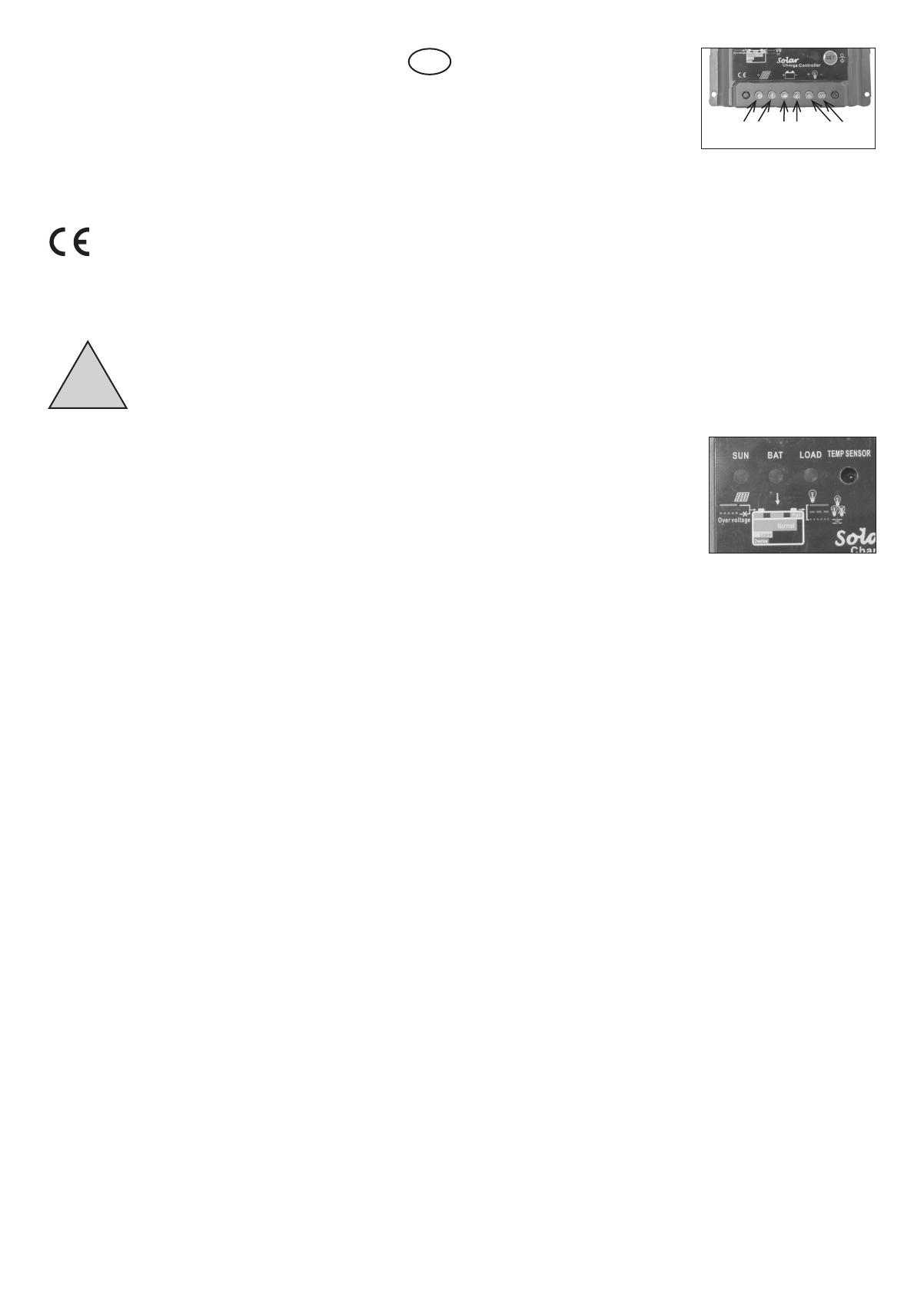
4.3 Connection:
1. The battery cable is connected at rst.
First connect the battery cable with the
connection of the controller (battery symbol)
andthenwiththebattery’spoles.
Note: Pay attention to the correct polarity
when connecting the battery!
CAUTION: Danger of burning in case of a short circuit on the battery.
2. IfthepolarityiscorrectthentheLED„BAT“lightsup;inordertoperformacheck,
pressthebutton„SET“.Incaseitshouldnotlightup,checkthecableconnection
and the connection for the correct polarity.
3. Now connect the solar module cable to the charge controller (solar module
symbol). In doing so, please also pay attention to the correct polarity! Now connect
the cable with the connection on the solar module.
Note: Pay attention to the correct polarity when connecting the solar module!
4. TheLED„SUN“willbeilluminatedwhenthesunisshining.Incaseitshouldnotbe
illuminated, check the cable connection and the polarity.
5. Now connect the devices to be operated with the load output of the charge
controller (lamp symbol). In doing so, please also pay attention to the correct
polarity.
Note: Pay attention to the correct polarity when connecting the consumers! The
connected devices may be destroyed in case of an incorrect polarity!
5. LED Displays
- LED Display „Sun“
Green: If the charge controller was connected
correctly and the sun is shining onto the
photovoltaicsmodule,thenthegreenLED„SUN“
is illuminated and indicates that a charging
currentisowing.
Flashing green: IftheLED„SUN“isashingquickly,thenthereisanovervoltage.
Please pay attention to the technical data in item 8.
- LED Display „BATT“
Green: The LED lights up green if the battery voltage is in a normal range.
Flashing green:TheLED„BATT“ashesslowlyifthebatteryisfullycharged.
Orange:TheLEDdiplay„BATT“lightsuporangeincaseofanundervoltage.
Red: Incaseofadeepdischarge,theLED„BATT“willlightupred.Thenthecontroller
will automatically switch off the load and the battery has to be charged by solar
radiation.
TheLED„BATT“willagainbeilluminatedgreenandtheoutputwillbereactivatedas
soonasthebattery’svoltagehasrecovered.
- LED Display „LOAD“
Green: TheLED„LOAD“lightsupgreeniftheloadoutputisactivated.
Slowly ashing red: TheLED„LAST/LOAD“ashesslowlyinrediftheloadcurrent
is 1.25 higher than the nominal current of the controller for 60 seconds or of the load
current is 1.5 times higher than the nominal current of the controller for 5 seconds.
Quickly ashing red: The controller switches of the power output in case of any
overload. The controller immediately switches of the power output in case of any
shortcircuitandtheLED„LOAD“ashesquickly.
In order to check the load connection, disconnect the part affected by the short
circuitandpressthebutton„SET“once.Thechargecontrollerwillrecommenceits
operation after 30 seconds or work normally the following day.
6. Operating Modes
The charge controller may work in 17 different operating modes. For the different
options, see item 6.
6.1 Setting Procedure:
Press the button „SET“ for 5 seconds to get into the programming mode. In the
indication„WORKMODE“,youwillndaashingnumber.Witheveryotherpressing
ofthebutton„SET“anothernumberwillappear.Pressuntilthenumberappearsthat
youneed.ThesettingisnishedassoonastheLEDnumberstopsashing.TheLED
number lights up every time the button is pressed.
6.2 Possible Modes:
- WORK MODE 0
At nightfall, the output is activated after approx. 10 minutes. The output is switched off
after approx. 10 minutes at the crack of dawn.
!
GB
solar panel battery load
+++
---


