Asus PRIME H310M-K User manual
- Category
- Motherboards
- Type
- User manual
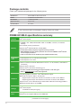
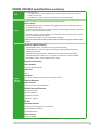
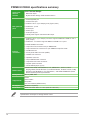
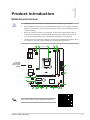
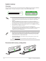
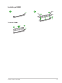
The Asus PRIME H310M-K motherboard features an LGA1151 socket, supporting 8th Generation Intel Core i7/i5/i3, Pentium, and Celeron processors. It boasts dual-channel DDR4 memory architecture, with support for up to 32GB of RAM at speeds of 2666/2400/2133 MHz. Expansion slots include one PCI Express 3.0/2.0 x16 slot and two PCI Express 2.0 x1 slots. Additionally, it offers integrated Intel HD graphics, Gigabit LAN, and a variety of connectivity options, making it suitable for building a budget-friendly yet capable system for everyday computing, multimedia, or office tasks.
The Asus PRIME H310M-K motherboard features an LGA1151 socket, supporting 8th Generation Intel Core i7/i5/i3, Pentium, and Celeron processors. It boasts dual-channel DDR4 memory architecture, with support for up to 32GB of RAM at speeds of 2666/2400/2133 MHz. Expansion slots include one PCI Express 3.0/2.0 x16 slot and two PCI Express 2.0 x1 slots. Additionally, it offers integrated Intel HD graphics, Gigabit LAN, and a variety of connectivity options, making it suitable for building a budget-friendly yet capable system for everyday computing, multimedia, or office tasks.


-
 1
1
-
 2
2
-
 3
3
-
 4
4
-
 5
5
-
 6
6
-
 7
7
-
 8
8
-
 9
9
-
 10
10
-
 11
11
-
 12
12
-
 13
13
-
 14
14
-
 15
15
-
 16
16
-
 17
17
-
 18
18
-
 19
19
-
 20
20
-
 21
21
-
 22
22
-
 23
23
-
 24
24
-
 25
25
-
 26
26
-
 27
27


Asus PRIME H310M-K User manual
- Category
- Motherboards
- Type
- User manual
The Asus PRIME H310M-K motherboard features an LGA1151 socket, supporting 8th Generation Intel Core i7/i5/i3, Pentium, and Celeron processors. It boasts dual-channel DDR4 memory architecture, with support for up to 32GB of RAM at speeds of 2666/2400/2133 MHz. Expansion slots include one PCI Express 3.0/2.0 x16 slot and two PCI Express 2.0 x1 slots. Additionally, it offers integrated Intel HD graphics, Gigabit LAN, and a variety of connectivity options, making it suitable for building a budget-friendly yet capable system for everyday computing, multimedia, or office tasks.
Ask a question and I''ll find the answer in the document
Finding information in a document is now easier with AI
Related papers
-
Asus PRIME H310M-C R2.0/CSM User manual
-
-
Asus PRIME H310M-CS R2.0 User manual
-
Asus PRIME H310I-PLUS R2.0/CSM User manual
-
-
Asus PRIME H370-A User manual
-
-
Asus PRIME B365M-K/CSM User manual
-
-