
Low temperature burners - INDITHERM®
www.maxoncorp.com
combustion systems for industry
MAXON reserves the right to alter specifications and data without prior notice.
© 2008 Copyright Maxon Corporation. All rights reserved.
1-2.3-6
E-m-7/08
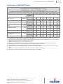
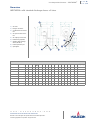
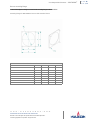
Specifications of INDITHERM® burners
[1] sg (specific gravity) = relative density to air (density air = 1.293 kg/Nm3.
[2] Back pressure = static pressure in the combustion chamber where the flame develops. Data in this table are given for 0 and 1.5 mbar back
pressure.Combustion air flow valid for all listed maximum capacities.
[3] Maximum capacity when firing at 3% vol. O2 level in the flue gas.
[4] Minimum capacity without pilot gas. If lower minimum capacities are required, refer to chapter ‘minimum capacities’ in this section.
[5] With direct ignition (no pilot), start capacity should be equal or higher than the stated pilot capacity.
[6] Differential pressure measured between burner test connection and combustion chamber.
[7] Gas differential pressures for natural gas at burner inlet. This pressure should be available at burner inlet throughout the entire capacity
range.
[8] Differential pressure to be measured between burner test connection and combustion chamber.
[9] Flame lengths are derived from measured lab data. Actual flame lengths can differ slightly.
Typical burner data
Fuel: natural gas at 15° C with 10.9 kWh/Nm³ HHV - sg = 0.6 [1]
Combustion air: 15° C - 21 % O2 - 50 % humidity - sg = 1.0 [1]
Stated pressures are indicative. Actual pressures are a function of air humidity, altitude, type of fuel, and gas quality.
Burner size & type 100 300 550 700 850 1100 1500 1800
back pressure
[2] mbar
Max. capacity [3] kW (HHV) 0 125 340 550 720 850 1050 1472 1800
1.5 110 285 500 675 775 880 1266 1693
Min. capacity [4] kW (HHV) 0- 1.5 5.0 6.0 10 15 15 25 25 25
Pilot capacity [5] kW (HHV) 0-1.5 7.5 10.0 15 25 25 40 40 40
Combustion air differential pres-
sure [6] mbar 0 6.5 4.5 6.4 7.9 9 5 6.4 13
1.5 5 3.2 5 7.3 7.5 3.5 4.7 11.5
Combustion air flow m3/h 0 136 360 615 755 910 1100 1611 1850
1.5 119 304 545 728 831 920 1386 1740
Gas differential pressure at inlet
[7] mbar 0 3.4 7.5 6.4 10.3 13.3 19.8 5.8 10
Gas differential pressure at test
connection [8] mbar 0 2.7 6.7 5.4 7.1 12 17.7 5.5 9.3
1.5 2.1 4.7 4.5 6.3 10 12.4 4 8.2
Flame length [9] m 0-1.5 1 1.2 2 2.1 2 2.3 2.6 3-4

Low temperature burners - INDITHERM®
www.maxoncorp.com
combustion systems for industry
MAXON reserves the right to alter specifications and data without prior notice.
© 2008 Copyright Maxon Corporation. All rights reserved.
1-2.3-7
E-m-7/08
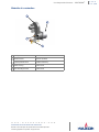
Materials of construction
1 Housing Cast iron
2Standard sleeve AISI 310 (1.4841)
High temperature block Castable refractory
3Blower housing Carbon steel
4Motor mounting bracket Carbon steel
1
2
3
4

Low temperature burners - INDITHERM®
www.maxoncorp.com
combustion systems for industry
MAXON reserves the right to alter specifications and data without prior notice.
© 2008 Copyright Maxon Corporation. All rights reserved.
1-2.3-8
E-m-7/08
Selection criteria
Application details
Because of the burner’s versatility there are numerous types of applications for INDITHERM® burners. All types of indirect-fired
applications can be equipped with this simple, industrial burner. Among the major applications there are automotive paint-bake
ovens and surface treatment, bakery ovens and dryers for the food industry.
Available INDITHERM® burner versions and options
INDITHERM® burners are designed to operate on natural gas only.
All burners are available in ANSI and ISO version. Each version will have the main gas inlet connection following either NPT or ISO
standards.
All burners include an adjustable orifice needle valve for pilot flame fine tuning, provision for UV-scanner connection and a
stainless steel combustion sleeve.
Options
Every burner has a set of options available, according to the table below:
Exception:
HTS High temperature discharge sleeve
FLR Combustion air filter box, recommended in extremely dusty surround-
ings
DI Direct ignited: in this case the adjustable orifice will be removed and the
pilot connection at the burner will be plugged
UVC Burner flame scanner connection prepared for UV-scanner mounting
(scanner not included)
CBL Connecting bracket and linkage for control motor mounting (control
motor make and type to be specified)
FR Flame rod, only to be used in limited number of applications, see
page 1-2.3-11
The spark ignitor is standard included on the burner.

Low temperature burners - INDITHERM®
www.maxoncorp.com
combustion systems for industry
MAXON reserves the right to alter specifications and data without prior notice.
© 2008 Copyright Maxon Corporation. All rights reserved.
1-2.3-9
E-m-7/08
Burner designation
Fuels
INDITHERM® burners are designed to operate on natural gas. For propane and butane operation a standard INDITHERM®
burner can not be used. Contact MAXON when the use of gases other than natural gas is inevitable.
Burner discharge sleeve
The burner discharge sleeve is available in different materials and geometries:
Standard version with circular stainless steel discharge sleeve and square burner mounting plate.
High temperature version with refractory block for installation in applications where high temperatures can be expected.
In following cases the use of high temperature version discharge sleeve is required:
Dimension A is larger than 50mm
Insufficient low temperature process air is available to cool the discharge sleeve
No process air is available ( typical in indirect fired applications)
Process air is entered downstream of the burner, being unable to flow over the burner discharge sleeve
Burner type Burner size Burner gas connection Discharge sleeve Ignition Flame supervision
INDITHERM®300 ISO HTS DI UVC
Burner size
100
300
550
700
850
1100
1500
1800
Burner gas connection
ISO: ISO threated
NPT: NPT threaded
Discharge sleeve
HTS: High temperature
STD: standard version, stainless steel
Ignition
DI: Direct Ignition (plugged pilot port)
PL: Pilot burner
Flame supervision
UVC: prepared for UV-scanner mounting
FRC: prepared for flame rod mounting
Process air
A

Low temperature burners - INDITHERM®
www.maxoncorp.com
combustion systems for industry
MAXON reserves the right to alter specifications and data without prior notice.
© 2008 Copyright Maxon Corporation. All rights reserved.
1-2.3-10
E-m-7/08
Control motor mounting plate
The INDITHERM® burner can be equipped with an electrical or pneumatic control motor for capacity control. A broad range of
mounting plates are available to accept almost any common control motor on the market. Required torque = 1.2 Nm.
Maximum capacities
INDITHERM® burners will have different maximum capacities depending on burner size and application back pressure.
Refer to table on page 1-2.3-6 for maximum capacities.
Capacities are stated for firing at zero back pressure and for 1.5 mbar back pressure, both at 3 % O2 level in the exhaust gases.
Minimum capacities
The minimum capacities depend on burner size and can be found in the table at page 1-2.3-6. The capacities in this table are those
that still allow a stable flame on main gas. When lower capacities are required, using a continuous pilot can be a solution. In this
case, the internal gas control valve of the burner can be closed even more at minimum position, while the minimum required gas
flow to maintain a stable flame can be adjusted using a needle valve on the pilot gas.
Preheated air
The INDITHERM® burner is designed to operate with non preheated combustion air. Although, the burner materials are suitable to
withstand up to 200° C temperatures, the burner will not perform according to the specifications page page 1-2.3-6 when the
combustion air is preheated. Contact MAXON for more details.
Process temperature
The high temperature refractory block permits operation of combustion chamber temperatures up to 950 °C . When using a
standard discharge sleeve, proper circulation of cold process air around the entire discharge sleeve should be present at all times.
Piloting and ignition
INDITHERM® burners have an internal pilot burner. Piloting is accomplished by internally bypassing the built-in gas butterfly valve
which is in the minimum position at low fire. The pilot gas is admitted to the gas nozzle via the main gas conduit and is injected
through the same gas nozzle ports as the main gas. The pilot gas adjusting valve allows for easy and precise adjusting of the pilot
flame.
The use of an intermittent pilot is technically possible on this burner and could result in lower minimum capacities.
Use minimally 5000 V/200 VA ignition transformers for sparking of the spark ignitor. Locate pilot gas valves as close as possible
to the pilot burner gas inlet, to have fast ignition of the pilot burner. When igniting the main gas, the capacity rating of the burner at
that point shall be limited.
Direct ignition
In case the use of a pilot burner is not required, the INDITHERM® burner can be direct ignited on main gas.
The pilot gas inlet should be plugged. When direct igniting an INDITHERM® burner, the capacity setting during ignition should be
limited. Direct ignition at high capacity is not allowed.
Typical ignition sequences
Pre purge of burner and installation, according to the applicable codes and the installation’s requirements.
Burner capacity control valve shall be in the start position to allow minimum combustion air flow to the burner.
Pre-ignition (typically 2 s sparking in air).
Open pilot gas and continue to spark the igniter (typically 5 s).
Stop sparking, continue to power the pilot gas valves and start flame check.
Check pilot flame stability (typical 5 s to prove the stable pilot).
Open main gas valves and allow enough time to have main gas in the burner. (typical 5 s + time required to have main gas in
the burner).
Close the pilot gas valves.
Release to modulation (allow modulation of the burner).
Above sequences shall be completed to include all required safety checks during the start-up of the burner (process & burner
safeties).

Low temperature burners - INDITHERM®
www.maxoncorp.com
combustion systems for industry
MAXON reserves the right to alter specifications and data without prior notice.
© 2008 Copyright Maxon Corporation. All rights reserved.
1-2.3-11
E-m-7/08
Flame supervision
Flame supervision can be accomplished by use of a UV-scanner for all INDITHERM® burners and sizes. The scanner connection
is 1”. Due to the presence of gas at the scanner port, only tight scanners can be used.
The use of a flame rod is only possible in a limited range of applications where the standard discharge sleeve is used. A flame rod
combined with a high temperature discharge sleeve would generate a flame signal too low for proper flame scanning.
Contact MAXON for more details when considering a flame rod.
Flame development
INDITHERM® burners shall be installed in combustion chambers that allow full development of the burner flame.
Consult MAXON for proper combustion chamber lay-out.
Gas pipe train design
The INDITHERM® burner is very sensitive to variations in gas pressures at burner gas inlet. The burner gas inlet pressure should
not vary more then 2.5 mbar between high and low capacity.
Process back pressures
The INDITHERM® burner can operate between 0 and 1.5 mbar back pressure. The burner should not be used on applications
where back pressures would fall outside these limits. It is possible to mount the burner on a process with changing back pressures
as long as the fluctuating pressures stay within the 0 to 1.5 mbar limit.
Measuring equipment for burner commissioning
The burner gas pressures and air pressures as mentioned in table on page 1-2.3-6 should be used as a guideline for burner
system design and to have an approximative value for burner set up.To adjust the burner properly during commissioning, the
oxygen content in the flue gas should be measured. A properly adjusted burner in an indirect fired application should have
approximately 3% O2 in the stack at maximum capacity.

Low temperature burners - INDITHERM®
www.maxoncorp.com
combustion systems for industry
MAXON reserves the right to alter specifications and data without prior notice.
© 2008 Copyright Maxon Corporation. All rights reserved.
1-2.3-12
E-m-7/08
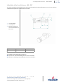
Dimensions
INDITHERM® with standard discharge sleeve - all sizes
[1] gas inlet is threaded, available in ISO or NPT.
1) Gas inlet
2) Pilot gas connection
3) Combustion air test connec-
tion
4) Gas pressure test connec-
tion
5) 90° capacity control crank
6) Filter housing (optional)
7) Stainless steel discharge
sleeve (standard)
8) Flame supervision port
9) Spark ignitor
Dimensions in mm unless stated otherwise
burner size gas inlet [1] ABC
ØD E F G H I J K L M N Ø P S Weight (kg)
100 1” 365 225 200 160 111 442 93 390 431 224 289 353 184 214 13 5 30
300 1 1/4” 365 224 200 210 111 442 91 390 431 224 289 353 226 264 13 5 34
550 1 1/2” 514 255 200 260 138 541 100 435 462 308 367 400 286 318 13 8 50
700 2” 598 255 200 260 138 786 71 435 500 387 403 448 286 318 13 8 50
850 2” 598 255 200 260 138 777 71 465 498 387 403 448 286 318 13 8 50
1100 2” 597 365 200 311 165 777 136 560 593 387 403 448 340 375 13 8 70
1500 2” 597 365 200 311 165 777 136 560 593 387 403 448 340 375 13 8 70
1800 3” 659 365 200 311 165 809 136 605 663 451 452 480 340 375 13 8 70
1
9
6
8
2
4
7
5
3

Low temperature burners - INDITHERM®
www.maxoncorp.com
combustion systems for industry
MAXON reserves the right to alter specifications and data without prior notice.
© 2008 Copyright Maxon Corporation. All rights reserved.
1-2.3-13
E-m-7/08
INDITHERM® with high temperature discharge sleeve - all sizes
[1] Gas inlet is threaded, available in ISO or NPT.
1) Gas inlet
2) Pilot gas connection
3) Combustion air test connec-
tion
4) Gas pressure test connec-
tion
5) 90° capacity control crank
6) Filter housing (optional)
7) High temperature discharge
sleeve
8) Flame supervision port
9) Spark ignitor
Dimensions in mm unless stated otherwise
burner size gas inlet [1] ABC
ØD E F G H I J K L ØM ØN Ø P S Weight (kg)
100 1” 365 232 200 257 111 442 100 397 438 224 289 353 320 357 14 12 47
300 1 1/4” 365 231 200 305 111 442 98 397 438 224 289 353 368 405 14 12 57
550 1 1/2” 514 259 200 357 138 541 104 439 466 308 367 400 420 457 14 12 83
700 2” 598 259 200 357 138 786 75 439 504 387 403 448 420 457 14 12 83
850 2” 598 259 200 357 138 777 75 469 502 387 403 448 420 457 14 12 83
1100 2” 597 369 200 408 165 777 140 564 597 387 403 448 471 508 14 12 110
1500 2” 597 369 200 408 165 777 140 564 597 387 403 448 471 508 14 12 110
1800 3” 659 369 200 408 165 809 140 609 667 451 452 480 471 508 14 12 110
18
6
57
9
4
2
3

Low temperature burners - INDITHERM®
www.maxoncorp.com
combustion systems for industry
MAXON reserves the right to alter specifications and data without prior notice.
© 2008 Copyright Maxon Corporation. All rights reserved.
1-2.3-14
E-m-7/08
Adjustable orifice for pilot burner - ADJ-ORF
This orifice is standard included with the burner and is factory mounted onto the burner pilot gas port. In case a burner has been
ordered for direct ignition, this adjustable orifice is omitted.
Two available versions depending on burner size:
ADJ-ORF-STD: with standard drilling for burner sizes 100 and 300
ADJ-ORF-HC: with larger internal drilling for burner sizes 550 and up
1) Gas outlet 3/8” NPT
2) Gas inlet 3/8” NPT
3) Protection cap: remove to
a ccess fl o w a d justme n t s c re w
HEX 3.8 mm
A B C
38 mm 87.5 mm 19 mm

Low temperature burners - INDITHERM®
www.maxoncorp.com
combustion systems for industry
MAXON reserves the right to alter specifications and data without prior notice.
© 2008 Copyright Maxon Corporation. All rights reserved.
1-2.3-15
E-m-7/08
Spark ignitor - SI-1/2
The spark ignitor is standard included with the burner. It is advised to keep at least one additional spark ignitor available as a spare
item for maintenance.
This spark ignitor can be mounted directly onto the burner spark ignitor connection port.
To be used on all burner sizes. See table below for mounting position C depending on burner size.
Filter Elements - FLT- INDI
Replacement elements for the optional INDITHERM®burners combustion air filters.
Available in 4 types to cover all burner sizes.
FLT-INDI-1 for burner sizes 100 and 300
FLT-INDI-2 for burner size 550
FLT-INDI-3 for burner sizes 700-850-1100-1500
FLT-INDI-4 for burner size 1800
1) 1/2” NPT
Dimensions in mm unless stated otherwise
burner size A B C D Ø E
100 165 140 33 5 14
300 165 140 37 5 14
550-850 165 140 31 5 14
1100-1800 165 140 33 5 14

Low temperature burners - INDITHERM®
www.maxoncorp.com
combustion systems for industry
MAXON reserves the right to alter specifications and data without prior notice.
© 2008 Copyright Maxon Corporation. All rights reserved.
1-2.3-16
E-m-7/08
Gaskets - GSK- INDI
These gaskets are used to seal the mounting plate of the burner and the duct wall. Optionally available in 2 different types:
GSK-INDI-STD to be used in combination with standard discharge sleeves (square)
GSK-INDI-HT to be used in combination with high temperature discharge sleeves (round)
Gasket type Burner Type Geometry
GSK-INDI-STD-1 100 square
GSK-INDI-STD-2 300 square
GSK-INDI-STD-3 550-850 square
GSK-INDI-STD-4 1100-1800 square
GSK-INDI-HT-1 100 round
GSK-INDI-HT-2 300 round
GSK-INDI-HT-3 550-850 round
GSK-INDI-HT-4 1100-1800 round

Low temperature burners - INDITHERM®
www.maxoncorp.com
combustion systems for industry
MAXON reserves the right to alter specifications and data without prior notice.
© 2008 Copyright Maxon Corporation. All rights reserved.
1-2.3-17
E-m-7/08
Installation and operation instructions for INDITHERM® burners
Application requirements
Supporting burner air and gas piping
The INDITHERM®burner shall not be used as support for the piping to the burner. Gas and air piping shall be supported in such a
way that no additional loads will be created on the burner.
Burner mounting flange loads
Check burner weight and reinforce burner mounting flange or combustion chamber/furnace back wall if necessary to support the
complete burner weight.
Installation instructions
Storage of INDITHERM® burners
INDITHERM®burners shall be stored dry (inside). Burner blocks have been cured carefully before shipment and shall be kept dry.
Wetting of the blocks could result in premature failures.
Handling of INDITHERM® burners
INDITHERM®burners are shipped as complete units. Handle burners with care, using proper equipment during unpacking,
transport, lifting and installation. Any impact on the burner could result in damage. To prevent damage in transit, accessories such
as flame rods, control valves, UV-scanners, may be packed separately and shipped loose.
Orientation of INDITHERM® burners
INDITHERM® burners can be mounted and fired in any direction. However we advise to avoid orientations which can permit flame
supervision ports to collect debris and/or moisture. Also check limitations on orientation of other components mounted on the
burner head.
Burner mounting
Bolt the burner to the installation’s burner mounting flange. Use proper gaskets between burner and burner mounting flange
(option available).Tighten the flange bolting with correct torque. Retighten all bolts after first firing and regularly after
commissioning.

Low temperature burners - INDITHERM®
www.maxoncorp.com
combustion systems for industry
MAXON reserves the right to alter specifications and data without prior notice.
© 2008 Copyright Maxon Corporation. All rights reserved.
1-2.3-18
E-m-7/08
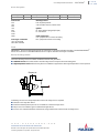
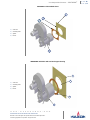
INDITHERM® with standard sleeve
INDITHERM® with block with seal and support housing
1) oven wall
2) mounting studs
3) gasket
4) burner
1) oven wall
2) mounting studs
3) gasket
4) burner
2
3
4
1
1
2
3
4

Low temperature burners - INDITHERM®
www.maxoncorp.com
combustion systems for industry
MAXON reserves the right to alter specifications and data without prior notice.
© 2008 Copyright Maxon Corporation. All rights reserved.
1-2.3-19
E-m-7/08
Burner mounting flange
Refer to below figure to design a correct burner mounting flange on the installation.
Mounting flange for INDITHERM® burners with standard sleeve
Dimensions in mm unless stated otherwise
Burner size A B ØC D
100 184 214 185 M10
300 226 264 235 M10
550 286 318 285 M10
700 286 318 285 M10
850 286 318 285 M10
1100 340 375 336 M10
1500 340 375 336 M10
1800 340 375 336 M10

Low temperature burners - INDITHERM®
www.maxoncorp.com
combustion systems for industry
MAXON reserves the right to alter specifications and data without prior notice.
© 2008 Copyright Maxon Corporation. All rights reserved.
1-2.3-20
E-m-7/08
Mounting flange for INDITHERM® burners with high temperature block sleeve
Dimensions in mm unless stated otherwise
Burner size ØA ØB ØC D
100 282 320 357 M12
300 330 368 405 M12
550 382 420 457 M12
700 382 420 457 M12
850 382 420 457 M12
1100 433 471 508 M12
1500 433 471 508 M12
1800 433 471 508 M12

Low temperature burners - INDITHERM®
www.maxoncorp.com
combustion systems for industry
MAXON reserves the right to alter specifications and data without prior notice.
© 2008 Copyright Maxon Corporation. All rights reserved.
1-2.3-21
E-m-7/08
Start-up instructions for INDITHERM® burners
Instructions provided by the company or individual responsible for the manufacture and/or overall installa-
tion of a complete system incorporating MAXON burners take precedence over the installation and operat-
ing instructions provided by MAXON. If any of the instructions provided by MAXON are in conflict with local
codes or regulations, please contact MAXON before initial start-up of equipment.
Initial adjustment and light-off should be undertaken only by a trained commissioning engineer.
First firing or restart after shut-down
During first start-up of the burner, allow extended period at low firing range to minimize potential damage from accumulated
and retained moisture in refractory burner block.
During cold starts, the temperature rise shall be limited – allow the burner to fire on low fire for some time to allow the parts to
heat up slowly for maximum life.
Safety interlocks
Guarantee that all the required safety locks as described in the applicable local codes or regulations, or supplementary safety
blocks requested for safe operation of the overall installation, are working properly and resulting in a positive safety-lock of the
burner. Do not bypass any of these safety interlocks, this will result in unsafe operation.
Checks during and after start up
During and after start-up, check the integrity of the system. Check all bolted connections after first firing (first time on tempera-
ture) and retighten if necessary.
Purge
For safety reasons, it is required to purge the installation sufficiently long to ensure that all possible combustibles are evacu-
ated before ignition. Refer to the applicable local codes and your specific application requirements to determine the purge time.
Pilot ignition
Adjust pilot air flow and pilot gas regulator to correct set point before pilot ignition attempt.Turn adjustable orifice screw out
(counter-clockwise) several turns from its fully seated position. Refine during lighting of the pilot to a yellow/blue flame and/or
strongest stable flame signal.
Main burner ignition
Adjust the main gas regulator at the correct set point before igniting the main burner. Ensure that the gas/air ratio valve is in the
start position when lighting the main burner.
After ignition of main burner, allow some time on minimum capacity to allow the burner parts to heat up slowly.
Burner adjustment
Once the main flame is ignited, adjust gas pressure to the burner to have the required combustion quality. Slowly increase
capacity while observing the flame and measuring flue gas quality. Do not increase capacity too fast to avoid damage to burner
parts or furnace due to excessive temperature gradient.
Read the combustion system manual carefully before initiating the start-up and adjustment
procedure.Verify that all of the equipment associated with and necessary to the safe
operation of the burner system has been installed correctly, that all pre- commissioning
checks have been carried out successfully and that all safety related aspects of the
installation are properly addressed.

Low temperature burners - INDITHERM®
www.maxoncorp.com
combustion systems for industry
MAXON reserves the right to alter specifications and data without prior notice.
© 2008 Copyright Maxon Corporation. All rights reserved.
1-2.3-22
E-m-7/08
Maintenance and inspection
Safety requirements
Regular inspection, testing and recalibration of combustion equipment according to the installation’s manual are an integral part of
its safety. Inspection activities and frequencies shall be carried out as specified in the installation’s manual. Perform the following
activities at least annually as part of a recommended preventative maintenance routine:
Inspect burner internal parts for wear and oxidation, paying special attention to the refractory of the burner block
(when applicable).
Inspect associated control instruments and devices for function with particular attention to all safety permissive switches.
Perform leak tests on fuel shut off valves according to any schedule established by the authority having jurisdiction.
Visual inspections
Regular visual inspection of all connections (air and gas piping to the burner, bolting of the burner mounting flange and burner
flame shape and aspect are essential for safe operation.
Recommended spare parts
Keep local stock of spark igniter. It is not recommended to keep local stock of other burner parts. Consult installation manual for
burner spare parts and system accessories.
-
 1
1
-
 2
2
-
 3
3
-
 4
4
-
 5
5
-
 6
6
-
 7
7
-
 8
8
-
 9
9
-
 10
10
-
 11
11
-
 12
12
-
 13
13
-
 14
14
-
 15
15
-
 16
16
-
 17
17


Maxon Telecom 1800 User manual
- Type
- User manual
Ask a question and I''ll find the answer in the document
Finding information in a document is now easier with AI
Other documents
-
Maxon Wide Range Operating instructions
-
-
-
-
-
-
-
-
-