
Models:
KG2204 Naturally Aspirated
KG2204T Turbocharged
Propane, Liquefied Petroleum Gas (LPG)
Natural Gas (NG) Fueled
Engine
TP-6901 8/18b
Operation

2 TP-6901 8/18
WARNING: This product can expose you to chemicals, including carbon monoxide and
benzene, which are known to the State of California to cause cancer and birth defects or
other reproductive harm. For more information go to www.P65warnings.ca.gov
Product Identification Information
Product identification numbers determine service parts. Record the product identification numbers in the spaces below
immediately after unpacking the products so that the numbers are readily available for future reference.
Engine Identification
Record the product identification information from the engine nameplate.
Model Designation: __________________________
Serial Number: __________________________
Purchase Date
Upon purchase of your Kohler equipment, record the purchase date for reference when communicating with your authorized
Kohler distributor/dealer.

TP-6901 8/18 3
Table of Contents
Safety Precautions and Instructions ........................................................................................................................................ 5
Introduction .............................................................................................................................................................................. 13
Service Assistance................................................................................................................................................................... 14
Section 1. Components and Maintenance Locations ........................................................................................... 15
1.1 Model KG2204 Engine Side Views......................................................................................................................... 15
1.2 Model KG2204 Front and Rear Views .................................................................................................................... 16
1.3 Model KG2204T Engine Side Views ...................................................................................................................... 17
1.4 Model KG2204T Front and Rear Views.................................................................................................................. 18
Section 2. Operation ................................................................................................................................................ 19
2.1 Introduction ............................................................................................................................................................ 19
2.2 Fuel System ........................................................................................................................................................... 19
2.2.1 Components ............................................................................................................................................. 19
2.2.2 Fuel Specifications ................................................................................................................................... 25
2.2.3 NG to LPG Conversion ............................................................................................................................ 26
2.3 Before Starting ....................................................................................................................................................... 28
2.4 Starting ................................................................................................................................................................... 29
2.5 Cold Weather Starting ............................................................................................................................................ 30
2.6 Monitoring Engine Operation .................................................................................................................................. 31
2.7 Stopping ................................................................................................................................................................. 31
Section 3. Maintenance ........................................................................................................................................... 33
3.1 Introduction ............................................................................................................................................................ 33
3.2 Safety Precautions and Instructions ....................................................................................................................... 33
3.3 Fluid Specifications ................................................................................................................................................ 35
3.3.1 Oil Recommendations .............................................................................................................................. 35
3.3.2 Grease Recommendations ...................................................................................................................... 35
3.3.3 Coolant Recommendations ...................................................................................................................... 35
3.4 Periodic Maintenance Schedule ............................................................................................................................. 36
3.5 Engine .................................................................................................................................................................... 37
3.5.1 Check Engine Oil ..................................................................................................................................... 37
3.5.2 Change Engine Oil and Oil Filter .............................................................................................................. 39
3.5.3 Check and Clean the Air Filter ................................................................................................................. 42
3.5.4 Replace the Air Filter ............................................................................................................................... 42
3.5.5 Check, Adjust and Replace the Spark Plugs............................................................................................ 42
3.5.6 Ignition Timing .......................................................................................................................................... 44
3.6 Electrical System .................................................................................................................................................... 45
3.6.1 Check Battery and Connections ............................................................................................................... 45
3.6.2 Check and Adjust the Drive Belt .............................................................................................................. 46
3.6.3 Replace the Drive Belt ............................................................................................................................. 48
3.6.4 Check Wiring and Electrical Connections ................................................................................................ 50
3.7 Cooling system ....................................................................................................................................................... 51
3.7.1 Check Coolant Level and Condition ......................................................................................................... 51
3.7.2 Check Hoses and Clamps........................................................................................................................ 51
3.7.3 Draining and Replacing the Coolant ........................................................................................................ 51
3.8 Fuel System ........................................................................................................................................................... 52
3.8.1 Check Fuel Supply Pipe and Connections ............................................................................................... 52
3.8.2 Check Fuel Level (LPG only) ................................................................................................................... 52
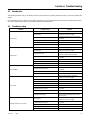
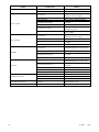
Section 4. Troubleshooting ..................................................................................................................................... 53
4.1 Introduction ............................................................................................................................................................ 53
4.2 Troubleshooting ..................................................................................................................................................... 53

4 TP-6901 8/18
Section 5. Storage.................................................................................................................................................... 55
5.1 Preparation ............................................................................................................................................................. 55
5.2 Short-Term Storage (Less than 30 Days) ............................................................................................................... 55
5.3 Long-Term Storage (More than 30 Days) ............................................................................................................... 56
5.4 Maintenance while in Storage ................................................................................................................................ 56
5.5 Removal from Storage ........................................................................................................................................... 56
Section 6. Specifications ......................................................................................................................................... 57
6.1 Engine Specifications ............................................................................................................................................. 57
6.2 Main Components Specifications ........................................................................................................................... 57
6.3 Adjustment Specifications ...................................................................................................................................... 58
6.4 Torque Specifications ............................................................................................................................................. 58
6.5 Standard Torque Specifications ............................................................................................................................. 59

TP-6901 8/18 5
Safety Precautions and Instructions
Read and follow all safety precautions and instructions. SAVE THESE INSTRUCTIONS.
This manual has several types of safety precautions and instructions: Danger, Warning, Caution, and Notice.
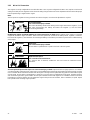
DANGER
Danger indicates the presence of a hazard that will cause severe personal injury, death, or substantial property damage.
WARNING
Warning indicates the presence of a hazard that can cause severe personal injury, death, or substantial property
damage.
CAUTION
Caution indicates the presence of a hazard that will or can cause minor personal injury or property damage.
NOTICE
Notice communicates installation, operation, or maintenance information that is safety related but not hazard related.
Note:
A Note is used to inform you of important installation, operation, or maintenance information.
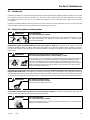
Accidental Starting
WARNING
Accidental starting.
Can cause severe injury or death.
Disconnect the battery cables before working on the engine. Remove the negative (–) lead
first when disconnecting the battery. Reconnect the negative (–) lead last when
reconnecting the battery.
Disabling the engine. Accidental starting can cause severe injury or death. Before working on the engine or connected
equipment, disable the engine as follows: 1) Disconnect the ignition coil. 2) Remove the battery cables, negative (–) lead first.
Reconnect the negative (–) lead last when reconnecting the battery. Follow these precautions to prevent the accidental starting
of the engine.

6 TP-6901 8/18
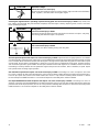
Battery
WARNING
Sulfuric acid in batteries.
Can cause severe injury or death.
Wear protective goggles and clothing. Battery acid may cause blindness and burn skin.
Battery electrolyte is a diluted sulfuric acid. Battery acid can cause severe injury or death. Battery acid can cause
blindness and burn skin. Always wear splashproof safety goggles, rubber gloves, and boots when servicing the battery. Do not
open a sealed battery or mutilate the battery case. If battery acid splashes in the eyes or on the skin, immediately flush the
affected area for 15 minutes with large quantities of clean water. Seek immediate medical aid in the case of eye contact. Never
add acid to a battery after placing the battery in service, as this may result in hazardous spattering of battery acid.
Battery acid cleanup. Battery acid can cause severe injury or death. Battery acid is electrically conductive and corrosive.
Add 500 g (1 lb.) of bicarbonate of soda (baking soda) to a container with 4 L (1 gal.) of water and mix the neutralizing solution.
Pour the neutralizing solution on the spilled battery acid and continue to add the neutralizing solution to the spilled battery acid
until all evidence of a chemical reaction (foaming) has ceased. Flush the resulting liquid with water and dry the area.
Battery gases. Explosion can cause severe injury or death. Battery gases can cause an explosion. Do not smoke or permit
flames or sparks to occur near a battery at any time, particularly when it is charging. Do not dispose of a battery in a fire. To
prevent burns and sparks that could cause an explosion, avoid touching the battery terminals with tools or other metal objects.
Remove all jewelry before servicing the equipment. Discharge static electricity from your body before touching batteries by first
touching a grounded metal surface away from the battery. To avoid sparks, do not disturb the battery charger connections while
the battery is charging. Always turn the battery charger off before disconnecting the battery connections. Ventilate the
compartments containing batteries to prevent accumulation of explosive gases.
Battery short circuits. Explosion can cause severe injury or death. Short circuits can cause bodily injury and/or equipment
damage. Disconnect the battery before maintenance. Remove all jewelry before servicing the equipment. Use tools with
insulated handles. Remove the negative (–) lead first when disconnecting the battery. Reconnect the negative (–) lead last when
reconnecting the battery. Never connect the negative (–) battery cable to the positive (+) connection terminal of the starter
solenoid. Do not test the battery condition by shorting the terminals together.

TP-6901 8/18 7
Engine Backfire/Flash Fire
WARNING
Risk of fire.
Can cause severe injury or death.
Do not smoke or permit flames or sparks near fuels or the fuel system.
Servicing the fuel system. A flash fire can cause severe injury or death. Do not smoke or permit flames or sparks near the
fuel mixer, fuel line, fuel filter, or other potential sources of fuel vapors. When removing the fuel line or fuel system be aware that
liquid propane can cause frostbite on contact.
Servicing the air cleaner. A sudden backfire can cause severe injury or death. Do not operate the engine with the air
cleaner/silencer removed.
Combustible materials. A fire can cause severe injury or death. Engine fuels and fuel vapors are flammable and explosive.
Handle these materials carefully to minimize the risk of fire or explosion. Equip the compartment or nearby area with a fully
charged fire extinguisher. Select a fire extinguisher rated ABC or BC for electrical fires or as recommended by the local fire code
or an authorized agency. Train all personnel on fire extinguisher operation and fire prevention procedures.
Troubleshooting and/or repairing the sensors or the ECM. A backfire due to an open fuel shut-off valve can cause
severe injury or death. If power is supplied to the shut-off valve during ECM or sensor troubleshooting, fuel may enter the air
intake manifold or the air cleaner and cause a backfire. Make sure that the fuel supply is turned OFF and that the fuel supply
valves are DISCONNECTED from the power source BEFORE turning the ECM power on.
Engine Fluids and Chemical Products
WARNING
Handling caustic engine fluids and chemical products.
Can cause severe chemical burns, nausea, fainting, or death.
Most chemicals such as used engine oil, antifreeze/coolant, rustproofing agent, inhibiting
oil, degreasing agent, spray paint, and adhesives are hazardous to health. Read and
follow the user information found on the packaging. Avoid inhalation and skin contact.
Use only in well-ventilated areas and use a protective mask when spraying. Store engine
fluids and chemical products in a locked cabinet. Contact your local recycling center for
disposal information and locations.
Fire-damaged or burned O-rings may cause the formation of hydrofluoric acid. Contact with hydrofluoric acid may
cause severe skin irritation and chemical burns. O-rings and other fluoroelastomer seals exposed to fire or temperatures
above 316°C (600°F) (i.e., during welding) may decompose forming hydrofluoric acid. Avoid inhalation or skin contact. Do not
incinerate O-rings. Dispose of O-ring waste material in a responsible manner.
Used engine oil. Contact with used engine oil may cause severe skin irritation. Repeated and prolonged skin exposure
may have other health risks. Used engine oil is a suspected carcinogen. Avoid contact with skin. Thoroughly wash your hands
and nails with soap and water shortly after handling used engine oil. Wash or dispose of clothing or rags containing used engine
oil. Dispose of used engine oil in a responsible manner. Contact your local recycling center for disposal information and locations.

8 TP-6901 8/18
Exhaust System
WARNING
Carbon monoxide.
Can cause severe nausea, fainting, or death.
The exhaust system must be leakproof and routinely inspected.
Carbon monoxide symptoms. Carbon monoxide can cause severe nausea, fainting, or death. Carbon monoxide is a
poisonous gas present in exhaust gases. Carbon monoxide is an odorless, colorless, tasteless, nonirritating gas that can cause
death if inhaled for even a short time. Carbon monoxide poisoning symptoms include but are not limited to the following:
Light-headedness, dizziness
Physical fatigue, weakness in joints and muscles
Sleepiness, mental fatigue, inability to concentrate or speak clearly, blurred vision
Stomachache, vomiting, nausea
If experiencing any of these symptoms and carbon monoxide poisoning is possible, seek fresh air immediately and remain active.
Do not sit, lie down, or fall asleep. Alert others to the possibility of carbon monoxide poisoning. Seek medical attention if the
condition of affected persons does not improve within minutes of breathing fresh air.
WARNING
Carbon monoxide.
Can cause severe nausea, fainting, or death.
Avoid inhaling exhaust fumes.
Engine Operation. Carbon monoxide can cause severe nausea, fainting, or death. Engine exhaust gases contain
poisonous carbon monoxide. Carbon monoxide is an odorless, colorless, tasteless, nonirritating gas that can cause death if
inhaled for even a short time. Avoid breathing exhaust fumes when working on or near the engine. Never operate the engine
inside a building. Never operate the engine where exhaust gas could seep inside or be drawn into a potentially occupied building
through windows, air intake vents, or other openings.

TP-6901 8/18 9
Fuel System
WARNING
Explosive fuel vapors.
Can cause severe injury or death.
Use extreme care when handling, storing, and using fuels.
The fuel system. Explosive fuel vapors can cause severe injury or death. Vaporized fuels are highly explosive. Use extreme
care when handling and storing fuels. Store fuels in a well-ventilated area away from spark-producing equipment and out of the
reach of children. Never add fuel to the tank while the engine is running because spilled fuel may ignite on contact with hot parts
or from sparks. Do not smoke or permit flames or sparks to occur near sources of spilled fuel or fuel vapors. Keep the fuel lines
and connections tight and in good condition. Do not replace flexible fuel lines with rigid lines. Use flexible sections to avoid fuel
line breakage caused by vibration. Do not operate the engine in the presence of fuel leaks, fuel accumulation, or sparks. Repair
fuel systems before resuming engine operation.
Explosive fuel vapors can cause severe injury or death. Take additional precautions when using the following fuels:
Propane (LPG)—Adequate ventilation is mandatory. Because propane is heavier than air, install propane gas detectors low in
a room. Inspect the detectors per the manufacturer’s instructions.
Natural Gas—Adequate ventilation is mandatory. Because natural gas rises, install natural gas detectors high in a room. Inspect
the detectors per the manufacturer’s instructions.
WARNING
Explosive fuel vapors.
Can cause fires and severe burns.
If a gaseous odor is detected, ventilate the area and contact an authorized service
technician.
Gas fuel leaks. Explosive fuel vapors can cause severe injury or death. Fuel leakage can cause an explosion. Check the
LPG vapor or natural gas fuel system for leakage by using a soap and water solution with the fuel system test pressurized to 6–
8 ounces per square inch (10–14 inches water column). Do not use a soap solution containing either ammonia or chlorine
because both prevent bubble formation. A successful test depends on the ability of the solution to bubble.
Hazardous Noise
CAUTION
Hazardous noise.
Can cause hearing loss.
Never operate the engine without a muffler or with a faulty exhaust system.

10 TP-6901 8/18
Hazardous Voltage/Moving Parts
CAUTION
Hazardous voltage.
Electrical shock can cause injury.
Do not touch wires while the engine is running. Stop the engine and disconnect the battery
leads, negative (-) lead first, before servicing the engine.
WARNING
Spring-loaded parts.
Can cause severe personal injury or property damage.
Wear protective goggles when servicing spring-loaded parts. Hold parts securely during
disassembly.
WARNING
Airborne particles.
Can cause severe injury or blindness.
Wear protective goggles and clothing when using power tools, hand tools, or
compressed air.
CAUTION
Damaged harmonic balancer, crankshaft, or flywheel.
Can cause personal injury.
Broken fragments from the harmonic balancer, crankshaft, and flywheel can be thrown
from the engine. Do not use a hammer to install or remove. Inspect these parts for
damage and replace if needed.
WARNING
Pinch and entanglement hazards.
Can cause severe injury and possible death.
Never check drive belt tension while the engine is running.
WARNING
Moving parts.
Can cause severe injury or death.
Operate the engine only when all guards and electrical enclosures are in place. Stay away
from moving parts while the engine is in operation.
Servicing the engine when it is operating. Exposed moving parts can cause severe injury or death. Keep hands, feet,
hair, clothing, and test leads away from the belts and pulleys when the engine is running. Replace guards, screens, and covers
before operating the engine.

TP-6901 8/18 11
Heavy Equipment
WARNING
Unbalanced weight.
Improper lifting can cause severe injury or death and equipment damage.
Use adequate lifting capacity.
Always maintain a safe distance from the equipment being lifted. Never stand under the
equipment.
Hot Parts
WARNING
Hot engine and exhaust system.
Can cause severe injury or death.
Do not work on the engine until it cools.
Servicing the exhaust system. Hot parts can cause severe injury or death. Do not touch hot engine parts. The engine and
exhaust system components become extremely hot during operation.
Hot engine components. Can cause severe injury or death. Never operate the engine with heat shields or guards removed.
WARNING
Hot coolant and steam.
Can cause severe injury or death.
Before removing the pressure cap, stop the engine and allow it to cool. Then loosen the
pressure cap to relieve pressure.

12 TP-6901 8/18

TP-6901 8/18 13
Introduction
This manual provides operating and maintenance instructions for Kohler engines. Keep this manual with the equipment for future
reference. Refer to the service manual for detailed information on adjusting and servicing the engine.
Read this manual and carefully follow all procedures and safety precautions to ensure proper equipment operation and to avoid
bodily injury. Read and follow the Safety Precautions and Instructions section at the beginning of this manual. Keep this manual
with the equipment for future reference.
Information in this publication represents data available at the time of print. Kohler Co. reserves the right to change this
publication and the products represented without notice and without any obligation or liability whatsoever.
This engine operates on either propane, liquefied petroleum gas (LPG), or natural gas (NG), which are extremely flammable
and explosive. Installation and repair of LPG/NG systems must be performed only by qualified technicians. Read this manual
and carefully follow all procedures and safety precautions to ensure proper equipment operation and to avoid bodily injury.
Regular maintenance is necessary for safe and efficient operation. Inspect the engine often and perform required maintenance
at prescribed intervals. Service work must be performed by appropriately skilled and suitably trained maintenance personnel
who are familiar with engine diagnostics and repair.
Unless otherwise specified, all units of measurement are metric, followed by the United States customary unit equivalent.
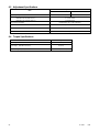
Related Literature
The following chart identifies related literature available for the KG2204/KG2204T engines. Only trained and qualified personnel
should install or service this engine.
Literature Type
Part Number
Engine Service Manual
TP-6902
Engine Service Manual, ECM Troubleshooting and Diagnostics
TP-6903
Engine Service Parts Manual
TP-6904
Contact a Kohler authorized distributor/dealer for all maintenance, service, and engine parts. To find a Kohler authorized
distributor/dealer, visit KOHLERPower.com or call 1-800-544-2444 (U.S. and Canada).

14 TP-6901 8/18
Service Assistance
For professional advice and conscientious service, please
contact your nearest Kohler distributor or dealer.
Visit the Kohler Co. website at KOHLERPower.com.
Look at the labels and decals on your Kohler product
or review the appropriate literature or documents
included with the product.
Call toll free in the US and Canada 1-800-544-2444.
Outside the US and Canada, call the nearest
regional office.
Headquarters Europe, Middle East,
Africa
(EMEA)
Kohler EMEA Headquarters
Netherlands B.V.
Kristallaan 1
4761 ZC Zevenbergen
The Netherlands
Phone: (31) 168 331630
Fax: (31) 168 331631
Asia
Pacific
Kohler Asia Pacific Headquarters
Singapore, Republic of Singapore
Phone: (65) 6264-6422
Fax: (65) 6264-6455
China
North China Regional Office, Beijing
Phone: (86) 10 6518 7950
(86) 10 6518 7951
(86) 10 6518 7952
Fax: (86) 10 6518 7955
East China Regional Office, Shanghai
Phone: (86) 21 6288 0500
Fax: (86) 21 6288 0550
India, Bangladesh, Sri Lanka
India Regional Office
Bangalore, India
Phone: (91) 80 3366208
(91) 80 3366231
Fax: (91) 80 3315972
Japan, Korea
North Asia Regional Office
Tokyo, Japan
Phone: (813) 3440-4515
Fax: (813) 3440-2727

TP-6901 8/18 15
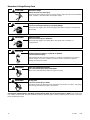
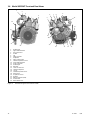
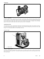
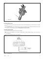
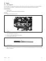
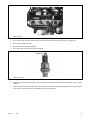
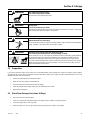
Section 1. Components and Maintenance Locations
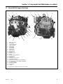
1.1 Model KG2204 Engine Side Views
1. Rocker Arm Cover
2. Rear Hanger
3. Crankcase Breather
4. Spark Plug Wires
5. Oil Filler Cap
6. Front Hanger
7. Air-Fuel Mixer
8. Throttle Body
9. TMAP Sensor
1
10. Intake Manifold
11. Flywheel
12. Exhaust Manifold
13. Oil Pan
14. Battery Charging Alternator
15. Oil Pump Drive
16. Ignition Coil
17. Crankshaft Position Sensor
18. Oil Dipstick and Tube
19. Knock Sensor (if equipped with turbocharger)
20. Oil Cooler Adapter (not included on all models)
21. Oil Pan Drain Plug
22. Oil Pressure Sender
23. Oil Filter Base
24. Oil Filter
1
Air Temperature / Manifold Absolute Pressure (TMAP)
Figure 1 KG2204 Engine Side Views
3
2
1
4
5
15
16
17
18
19
20
24
22
21
23
6
8
9
10
11
12
13
14
7

16 TP-6901 8/18
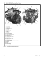
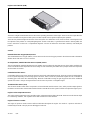
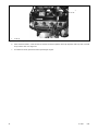
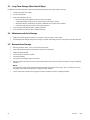
1.2 Model KG2204 Front and Rear Views
1. Air-Fuel Mixer
2. Throttle Body
3. TMAP Sensor
4. Upper Intake Manifold
5. PCV Valve
6. Rocker Arm Cover
7. Oil Filter
8. Ignition Coil
9. Oil Dipstick
10. Fuel Control Valve
11. Upper Coolant Outlet
12. Coolant Temperature Sensor
13. Drive Belt
14. Vibration Dampener
15. Crankshaft Position Sensor
16. Timing Cover
17. Oil Drain Plug
18. Oil Pressure Sensor (PGS)
19. Oil Filter Base
20. Oil Cooler Adapter (not included on all models)
21. Lower Intake Manifold
22. Flywheel
23. Exhaust Manifold Studs
24. Oil Pan
25. Exhaust Manifold
26. Battery Charging Alternator
27. Water Pump Inlet
Figure 2 KG2204 Engine Front and Rear Views
3
2
1
4
5
15
18
19
20
27
22
21
23
6
8
9
10
11
12
13
14
7
1
16
17
24
25
26

TP-6901 8/18 17
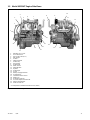
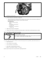
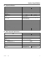
1.3 Model KG2204T Engine Side Views
1. Regulator to FCV Hose
2. FCV to Mixer Hose
3. Fuel Control Valve (FCV)
4. Rear Hanger
5. Oil Filter
6. Spark Plug Wires
7. Oil Filler Cap
8. Front Hanger
9. Throttle Body
10. TMAP Sensor
1
11. Intake Manifold
12. Flywheel
13. Turbocharger
14. Oil Pan
15. Battery Charging Alternator
16. Oil Pump Drive
17. Crankshaft Position Sensor
18. Ignition Coil
19. Oil Dipstick and Tube
20. Oil Cooler Adapter and Stand-off
21. Engine Control Module
22. Turbo Oil Feed Line
1
Air Temperature / Manifold Absolute Pressure (TMAP)
Figure 3 KG2204T Engine Side Views
3
2
1
4
5
17
20
21
22
6
8
9
7
19
18
16
15
14
13
10
11
12

18 TP-6901 8/18
1.4 Model KG2204T Front and Rear Views
1. Throttle body
2. Upper intake manifold
3. Fuel control valve
4. Oil filter
5. Coil
6. Spark plug wires
7. Oil dipstick
8. Upper coolant outlet
9. Coolant temperature sensor
10. Lower intake manifold
11. Turbo oil feed line
12. Turbocharger
13. Drive belt
14. Turbo oil return line
15. Vibration dampener
16. Oil pan
17. Crankshaft position sensor
18. Timing cover
19. Oil pressure sensor
20. Flywheel
21. Dual fuel regulator (DFR)
22. Air-fuel mixer
23. DFR breather hose
Figure 4 KG2204T Engine Front and Rear Views
5
1
2
3
4
6
7
8
9
10
11
12
13
14
15
16
17
18
19
20
21
22
23

TP-6901 8/18 19
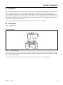
Section 2. Operation
2.1 Introduction
These four-stroke internal combustion engines are certified to operate on either Propane, Liquid Petroleum Gas (LPG) or Natural
Gas (NG). System configuration is factory preset for NG. Instructions for switching to LPG are provided within this section.
The fuel system on this engine is a closed loop design. As the engine runs, sensors located at various points within the system
provide continuous operating feedback to the Engine Control Module (ECM). The ECM adjusts the engine speed, ignition timing,
and fuel supply in response to changes in the applied load, surrounding air temperature, operating temperature of the engine,
and amount of oxygen present in the exhaust.
Refer to the equipment Operation Manual for specific information on how fault codes are displayed.
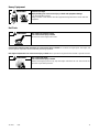
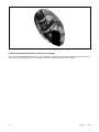
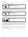
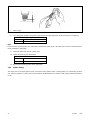
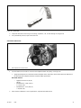
2.2 Fuel System
2.2.1 Components
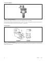
Fuel Shut-Off Valves
Figure 5 Fuel Shut-Off Valve
The fuel supply contains two fuel shut-off valves located upstream from the fuel connection point on the engine. Each valve
consists of a 12V solenoid and a normally closed port. When energized, the solenoid opens the valve and allows the LPG/NG
vapor to flow through the system.
The valves are open during the engine cranking and run cycles. Voltage to the valves is controlled by the ECM.

20 TP-6901 8/18
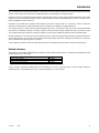
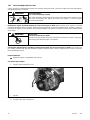
Fuel Pressure Regulator
Figure 6 Fuel Pressure Regulator
The fuel pressure regulator modulates the pressure of the LPG/NG vapor to the air-fuel mixer.
The fuel pressure regulator is not adjustable. However, a selector at the base of the regulator is rotated when switching from
NG to LPG and back. See the section “NG to LPG Conversion” for instructions.
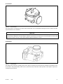
Fuel Control Valve
Figure 7 Fuel Pressure Regulator
The fuel control valve is an ECM-controlled vacuum switch that adjusts the fuel pressure delivered from the fuel pressure
regulator to the air-fuel mixer.
Page is loading ...
Page is loading ...
Page is loading ...
Page is loading ...
Page is loading ...
Page is loading ...
Page is loading ...
Page is loading ...
Page is loading ...
Page is loading ...
Page is loading ...
Page is loading ...
Page is loading ...
Page is loading ...
Page is loading ...
Page is loading ...
Page is loading ...
Page is loading ...
Page is loading ...
Page is loading ...
Page is loading ...
Page is loading ...
Page is loading ...
Page is loading ...
Page is loading ...
Page is loading ...
Page is loading ...
Page is loading ...
Page is loading ...
Page is loading ...
Page is loading ...
Page is loading ...
Page is loading ...
Page is loading ...
Page is loading ...
Page is loading ...
Page is loading ...
Page is loading ...
Page is loading ...
Page is loading ...
Page is loading ...
Page is loading ...
Page is loading ...
Page is loading ...
-
 1
1
-
 2
2
-
 3
3
-
 4
4
-
 5
5
-
 6
6
-
 7
7
-
 8
8
-
 9
9
-
 10
10
-
 11
11
-
 12
12
-
 13
13
-
 14
14
-
 15
15
-
 16
16
-
 17
17
-
 18
18
-
 19
19
-
 20
20
-
 21
21
-
 22
22
-
 23
23
-
 24
24
-
 25
25
-
 26
26
-
 27
27
-
 28
28
-
 29
29
-
 30
30
-
 31
31
-
 32
32
-
 33
33
-
 34
34
-
 35
35
-
 36
36
-
 37
37
-
 38
38
-
 39
39
-
 40
40
-
 41
41
-
 42
42
-
 43
43
-
 44
44
-
 45
45
-
 46
46
-
 47
47
-
 48
48
-
 49
49
-
 50
50
-
 51
51
-
 52
52
-
 53
53
-
 54
54
-
 55
55
-
 56
56
-
 57
57
-
 58
58
-
 59
59
-
 60
60
-
 61
61
-
 62
62
-
 63
63
-
 64
64


Kohler 36CCL Operating instructions
- Type
- Operating instructions
Ask a question and I''ll find the answer in the document
Finding information in a document is now easier with AI
Related papers
-
Kohler Portable Generator 24RCL User manual
-
Kohler KG200 Operating instructions
-
-
-
Kohler KG60 Operating instructions
-
-
-
-
-