
15
Instructions for use
Air-conditioner
PAC 36

16
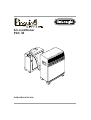
Please read this instruction
booklet carefully before
installing and using the
appliance. In this way, you will
obtain the best possible results
and maximum operating safety.
In particular, refer to the safety
warnings on page 24.
INTRODUCTION
The new PAC 36 is a highly versatile electronically-
controlled air-conditioner: it can be used as a
manual or automatic air-conditioner during the
summer.
This conditioner consists of two units: the internal
unit is designed to operate inside the room to be
conditioned; the external unit is installed in the
open.
The two units are connected by a special hose,
approximately 3,5 metres in length. This hose
contains the freon tubes, the electrical wiring and
the condensation discharge tube.
This appliance also has a SLEEP function. This
function activates a program studied and
designed to increase comfort during sleeping
hours. The program not only ensures perfect
silence (from both the internal and external units)
but also controls the temperature of the
environment, without lowering it excessively, to
produce the healthiest conditions.
TECHNICAL DATA
Power supply voltage see rating label
Maximum input power
(air-conditioning mode) see rating label
Cooling capacity* see rating label
Fan speeds 2
Maximum air flow 560 m3/h
Timer 24 h
Length of hose 3500 mm
Tube size 20 x 44 mm
Dimensions (internal unit):
•width 560 mm
• height 735 mm
• depth 355 mm
•weight 44 kg
Dimensions (external unit):
•width 450 mm
• height 470 mm
• depth 210 mm
•weight 14 kg
*Standard conditions:
Room temperature 27°C
47% relative
humidity
External temperature 35°C
41% relative
humidity
Temperature during night
Temperature
60 min. 120 min.
Time
IDEAL OPERATING CONDITIONS
Room temperature 21 ÷ 32°C
External temperature 21 ÷ 43°C

17
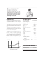
DESCRIPTION
INTERNAL UNIT
Condensation discharge tube
Castors
Power cable
Rear panel
Carrying handle
Removable filter
Power cable
Air intake grille
INTERNAL UNIT Connection hose
Air outlet grid
Control panel
Control panel cover
EXTERNAL UNIT

18
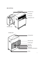
ACCESSORIES
ILLUSTRATION NUMBER SUPPLIED
2
4
4
2
1
2
1
4
DESCRIPTION
Wall bracket
Screws + wall plugs (Ø 6mm)
Nut and bolt (Ø 5mm)
Support belt with hook
Frame for connector hose
Castor stop
Condensation drainage coupling
Castors for external unit and washers
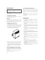
This appliance is fitted with a special HE (High
Efficiency) system for extra-low energy
consumption. When the unit is switched on,
this system requires about 4 minutes before
cold air is generated.

19
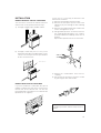
INSTALLATION
MODELS WITHOUT SPECIAL COUPLINGS
The hose which connects the internal unit to the
external unit can be positioned in two ways:
In this case, it is necessary to disconnect the
internal unit as follows:
1) Remove the plug from the wall socket.
2) Remove the rear panel (on the back of the
appliance) by unscrewing the four retaining
screws.
3) Remove the metal brackets which fasten the
hose to the appliance (N. 3).
4) Using a 24mm spanner, unscrew the union on
the coupling. When doing this, use a 19mm.
spanner to block the extrimity of the hose in
position.
Repeat this operation for the second union.
The path of the connector hose should be as
straight as possible, without sharp curves or
kinks.
5) Detach the condensation hose from its
coupling.
6) Disconnect the electrical connector socket
by pressing the two retainer tabs.
a) Through a slightly-open window or door.
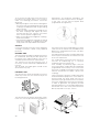
MODELS WITH SPECIAL COUPLINGS
If your air-conditioner is fitted with the special
rapid-fit coupling, the hose which connects the
internal unit to the external unit can also be
passed through a round hole in an external wall
(diameter: 6 cm. approx.).
ø6
cm 30
Frame for hose
b) Through a small hole (5.5 x 2.5 cm.) in the
lower part of the door or window frame. In this
case, it is necessary to use the special frame
for the connection hose.

20
To re-connect the ends of the connector hose to
the internal unit, repeat steps 1 to 6 in reverse
order. The following precautions should be
observed:
•Before passing the connector hose through the
hole in the wall, the threaded ends of the rapid
couplings should be protected using insulating
tape or similar.
•Fit the two upper refrigerant couplings to the
two lower couplings and tighten by hand,
ensuring that they are correctly connected.
Then use the spanner to tighten fully.
•After connecting the two refrigerant couplings,
fasten the brackets.
•Check that the refrigerant couplings are sealed
perfectly by wetting the couplings with a little
soapy water. No soap bubbles should form.
Attention
Connection and disconnection of the refrigerant
couplings should be carried out by qualified
personnel.
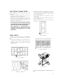
The external unit can also be mounted on a wall.
In this case, use the special wall-mount brackets.
EXTERNAL UNIT
The external unit can be positioned on a terrace
or balcony. In this case, it is not necessary to use
the fixing brackets.
Alternatively, for temporary installation, the
external unit can be hung as shown in the figure.
In this case, use the special support belts
(supplied with the appliance).
The external unit can be installed above or at the
same level as the internal unit, provided that the
difference in height between the two units does
not exceed 1.5 m.
The intake and outlet vents must not be obstructed.
Leave a space of at least 6 cm. between the rear
of the unit and the wall.
The condensation which forms when the unit is
used for air-conditioning (i.e. in summer)
evaporates from the external unit.
If the humidity is particularly high, it may be
necessary to fit the condensation discharge tube
(supplied with the machine). In this case, fit the
hose to the coupling on the bottom section of the
external unit (remove the rubber cap from the
coupling).
In the event there is still some condensation to be
eliminated and the equipment is connected to its
electrical feed, the waste pump may turn on
spontaneously to get rid of that excess moisture
even if the equipment itself has been turned off.
In order to guarantee the greatest possible
operational efficiency, you are advised to position
the external unit in such a way that it will not be
directly exposed to sun rays, rain etc.
INTERNAL UNIT
The internal unit should be installed in the room to
be conditioned. Generally,the ideal position for
the internal unit is under a window. In any case, it
should be positioned near an external wall.
The internal unit must be perfectly level. If
necessary, use the castor stops supplied with the
machine.
The air intake and outlet grilles should not be
obstructed in any way.
Coupling
Ring
Rubber cap
Castor
Washer

21
Do not cover
Close the doors
•Draw the curtains and/or partially close the
blinds to protect the room against direct sunlight.
This will increase the efficiency and economy
of the air-conditioner.
•Do not place objects of any kind on the air-
conditioner.
•Ensure that the air intake and discharge vents
are not obstructed.
•Make sure that there are no sources of heat in
the room.
Draw the curtains
Close the windows
FINAL CHECK
In order to ensure that your air-conditioner
operates with the maximum efficiency, make sure
that:
•all doors and windows in the room to be air-
conditioned are closed (except for temporary
installation, in which case a window must be left
partially open).
ELECTRICAL CONNECTIONS
Before plugging the unit into the mains, check the
following:
•the mains voltage must be the same as the
voltage shown on the rating plate
•the power socket and the mains circuit must be
suitable for the power requirements of the unit
•the socket must be suitable for the plug; if not,
have the socket replaced
•the power socket must be properly earthed.
The manufacturer declines all responsibility
for any damage or injury arising from non-
observance of this safety requirement.
This appliance is manufactured in
compliance with EEC Directive EN 44014
regarding the suppression of radio
interference.
Lower the blinds
YOUR AIR-CONDITIONER IS NOW READY FOR
USE.

22
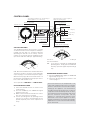
"SLEEP" signal lamp
Min. speed signal lamp
Air-cooling signal lamp
ON timer signal lamp
CONTROL PANEL
ON/OFF Timer key
"SLEEP" key
SETTING THE TIMER
Ther programmer/timer, like all clocks, must be
set to the exact time. If for example it is 4.00 p.m.
(16.00), turn the dial in a clockwise direction
(following the direction of the arrow) until the
number 16 is lined up with the tringular pointer
(the arrows indicates 4:00 p.m. approximately).
N.B.: Never turn the dial in anti-clockwise direction!
The timer is in effect, an electric clock and works
only if the plug is connected to the power supply.
Whenever the plug is disconnected or there is a
power failure, the programmer stops (the clock is
then "slow" and must be re-set.
Select operation "with timer" or "without timer".
21
20
19
16
Example: from 7 p.m. to 9 p.m.
The air-conditioner will now switch on each day at
the selected times.
N.B.: If you wish to override the programmed
operating times, simply press the ON/OFF
timer key (the timer signal lamp ON will go
out).
Timer Thermostat
slider
Air-cooling
signal lamp
ON/OFF key Automatic function signal lamp
Signal lamp indicating 3 min. wait (flashing) or
working appliance (on continuously)
Signal lamp mains (continuous light) or
malfunction (flashing light)
Fan speed key
Air-cooling key
Max. speed signal lamp
Pointer
21
20
19
16
Function
O
F
F
O
N
O
F
F
OPERATION WITH TIMER
1) Select the desired function as shown in the
chart overleaf.
2) Press the TIMER key, the "TIMER ON" signal
lamp will come ON.
3) Make sure that the timer indicates the correct
time (see instructions on setting).
4) Set the operating times by pushing out the
notches on the dial corresponding to the
period required (each notch represent 15
mins).
OPERATIONG WITHOUT TIMER
1) Press the TIMER ON key again, the TIMER ON
signal lamp will go out.
2) Select the desired function as shown in the
chart on page. 9.
For technical reasons, the temperature is not
expressed in degrees but by a line increasing in
thickness. We therefore recommend that when
starting up the appliance, the thermostat be
turned to maximum (thick green line = maximum
cold). When the desired temperature has been
reached move the thermostat slider slowly away
from the maximum cold position until the
appliance is switched off by operation of the
thermostat. In this way the appliance has been
programmed with the exact temperature degree
required, which is then maintained automatically
by the thermostat.

23
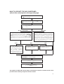
HOW TO OPERATE THE AIR-CONDITIONER
(refer to the control panel on the opposite page)
Plug the appliance into the power socket.
The pilot lamp lights.
▼
The appliance comes on.
If not, refer to page 25.
▼
To switch off the appliance,
press the ON/OFFr push-button.
This appliance is fitted with a special safety circuit. When the compressor switches off, this circuit
prevents it from switching on again for at least 3 minutes.
▼
Press the ON/OFF key. The conditioning and sleep
pilot lamps flash and the pilot lamp switches off.
▼
Press the button for the desired function:
=Air-conditioning
=Sleep
The signal lamps AUTO, MAX, MIN are flashing. Move
the slider on the thermostat towards MAX cold and press
the fan speed key. The correct sequence is MIN, MAX,
AUTO. When the key is pressed the first time, the MIN
lamp will flash for 3 - 4 seconds and the AUTO and MAX
lamps will go out (to modify the power, press the relevant
key).
AIR-CONDITIONING ▼
▼
The SLEEP warning lamp remains on. An automatic
program is enabled. The appliance is activated at
minimum speed. Once the ideal temperature has
been reached, the appliance controls the tempe-
rature in perfect silence, ensuring that it does not
drop excessively. The PAC 36 will only restart if the
temperature exceeds levels considered healthy.
N.B: The room should always be air-conditioned
before the SLEEP function is used.
The AUTO signal lamp comes
on. The appliance will
automatically select the fan
speed according to the internal
and external ambient
conditions. In this way, the
machine will provide the correct
cooling power and operate with
the minimum noise.
▼
AUTO
The MAX signal lamp comes on.
The appliance will function at
the maximum fan speed.
▼
MAX
The MIN signal almp comes on.
The appliance will function at
the minimum fan speed.
▼
MIN
▼
SLEEP
▼▼▼
▼
Select the desired operating mode “with timer” or
“without timer” (see previous page).

24
MAINTENANCE
Always remove the plug from the power
socket before carrying out any cleaning or
maintenance operations.
The air-conditioner must never be washed with
running water.
CLEANING THE CABINET
Clean the cabinet with a damp cloth and dry
carefully with a dry cloth.
Warning
Never use petrol, methylated spirits or solvents
for cleaning. Never spray insecticides or similar
products on the appliance, as these may seriously
damage the paintwork and plastic.
CLEANING THE AIR FILTER
•If the air filter is dirty, air circulation is reduced
and the efficiency of the air-conditioner will be
diminished. It is therefore recommended to
clean the filter at weekly intervals.
•Remove the filter as shown in the figure.
AT THE END OF THE SEASON
Switch off the appliance by pressing the ON/OFF
key.
Remove the plug from the drainage tube and
empty the water from the internal condensation
tray.
Clean the filter, and dry it carefully before
replacing.
Cover the appliance with a plastic bag to protect
it from dust.
•Use a vacuum cleaner to remove the dust from
the filter. If the filter is very dirty, wash it in
lukewarm water and rinse thoroughly. The tem-
perature of the water should not exceed 40°C.
Allow the filter to dry before replacing it in the
appliance.
AT THE BEGINNING OF THE SEASON
Check that the power cord and the plug are
undamaged and that the power socket is properly
earthed.
Ensure that the installation procedures are
followed meticulously.
IMPORTANT
•This appliance is designed to cool domestic
environments, and should not be used for any
other purpose.
•Any attempts to modify or alter the
characteristics of the appliance may be
dangerous.
•Should repair be necessary, contact your
nearest authorised Service Centre. Any repairs
carried out by unqualified personnel may be
dangerous.
•This appliance must be properly earthed. Have
your electrical system checked by a qualified
electrician.
•Avoid the use of extension cords.
•Always remove the plug from the power socket
before performing any cleaning or maintenance
operations.
•Do not move the appliance by pulling the
power cord.
•Do not install the appliance in a room which
might contain gas, oil or sulphur, or near sources
of heat.
•Do not place hot or heavy objects on the
appliance.
•Clean the air filter at least once weekly.
•The appliance should be transported in the
upright position or placed on its side.
Empty the condensation tray before transporting
the appliance.
After transportation, wait at least one hour before
switching on the appliance.
Filter

25
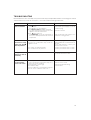
TROUBLESHOOTING
Most malfunctions are caused by a very minor and easily solved problem. Before contacting your nearest
authorised Service Centre for assistance, consult the troubleshooting chart below.
The air-conditioner
does not function •if the pilot lamp is not lit
-power failure
-the appliance is not plugged in
•if the Memo Control pilot lamp is flashing
-less than 3 minutes have passed since the
appliance was last switched off
•if the pilot lamp is lit
- in conditioning mode: the temperature in
the room is already lower than the selected
temperature
•wait until the power supply is restored
•insert the plug
•wait three minutes
•slide thermostat slider slowly to the
maximum cooling position
PROBLEM CAUSE SOLUTION
The air-conditioner
functions for a brief
period only. The
pilot lamp flashes
•the safety float has switched the appliance off
because the condensation tray inside the
appliance is full
•the control circuit board is faulty
•the condenser fas has jammed
•remove the plug from the drainage
tube and drain the condensation from
the tray.
If this fault persists, contact your
nearest Service Centre.
•contact your nearest Service Centre
•contact your nearest Service Centre
The appliance
switches on and off
constantly
•switch the appliance off and contact
your nearest Service Centre
The air-conditioner
functions but the
room is not cooled
•window open
•source of heat in the room (heater, lamp, etc.)
or the room is very crowded
•the thermostat is set too high
•the air filter is dirty
•the air-conditioner is not powerful enough for
the size or the conditions of the room
•close the window
•remove source of heat
•lower the thermostat setting
•clean the filter
-
 1
1
-
 2
2
-
 3
3
-
 4
4
-
 5
5
-
 6
6
-
 7
7
-
 8
8
-
 9
9
-
 10
10
-
 11
11


Ask a question and I''ll find the answer in the document
Finding information in a document is now easier with AI
Related papers
-
DeLonghi PAC 35 Instructions For Use Manual
-
-
-
DeLonghi PAC390 Owner's manual
-
-
DeLonghi PAC290 User manual
-
-
-
-
Other documents
-
Trotec PAC 4600 Operating instructions
-
Continental CE75096 Owner's manual
-
TECHNIBEL SCDF Series Operating instructions
-
Klimaire KIWQ18H2-3T / KOIQ18H2-3 Installation guide
-
Hitachi RAC-10SH3 User manual
-
Ecoair Crystal MK2 7000/9000BTU R290 Owner's manual
-
-
 Amcoraire 18EZ User manual
-
Whynter 14,000 BTU Portable Air Conditioner [ARC-148MS] User manual
-
Panasonic CS-MKE12NKU User manual
