
www.lg.com
Please read this installation manual completely before installing the product.
Installation work must be performed in accordance with the national wiring standards by
authorized personnel only.
Please retain this installation manual for future reference after reading it thoroughly.
CEILING CASSETTE - 1 WAY
Original instruction
[Representative] LG Electronics Inc. EU Representative : LG Electronics European Shared
Service Center B.V. Krijgsman 1, 1186 DM Amstelveen, The Netherlands
[Manufacturer] LG Electronics Inc. Changwon 2nd factory 84, Wanam-ro, Seongsan-gu,
Changwon-si, Gyeongsangnam-do, KOREA
INSTALLATION MANUAL
AIR
CONDITIONER
MFL68686521
Rev.00_052219
Copyright © 2017 - 2019 LG Electronics Inc. All Rights Reserved.
ENGLISH
ITALIANO
ESPAÑOL
FRANÇAIS DEUTSCH
РУССКИЙ ЯЗЫК
УКРАÏНСЬКА
ҚАЗАҚ ТІЛІ
БЕЛАРУСКАЯ МОВА
OʻZBEK TILI
ΕΛΛΗΝΙΚΆ
ČEŠTINA
NEDERLANDS
POLSKI
LIMBA ROMÂNĂ

2 Indoor Unit
Table of Contents
3 INSTALLATION PARTS
4 SAFETY PRECAUTIONS
10 INSTALLATION
10 Selection of the Best Location
12 Ceiling Dimension and Hanging Bolt Location
13 Wiring Connection
14 Installation of Decoration Panel (Panel Type)
15 Installation of Decoration Panel (Grille Type)
16 Drain Piping
17 DIP Switch Setting
18 Group Control Setting
23 Model Designation
23 Airborne Noise Emission
23 Limiting concentration
TABLE OF CONTENTS

Installation Manual 3
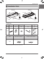
Installation Parts
ENGLISH
Wired Remote Controller
(Accessory)
Wired Remote Controller
(Accessory)
Air
Intake
Air Intake
Air
Intake
Air Outlet
Air Outlet
Installation Parts
Name
Quantity
Shape
for gas pipe
for liquid pipe
Clamp metal
2 EA
Insulation for
fitting
1 SET
Drain hose
1 EA
Plastic band
8 EA
Washer for
hanging bracket
4 EA
Name
Quantity
Shape
Paper pattern for installation
1 EA
Installation and Owner's manual
1 EA
Panel type Grille type
• Screws for fixing panels are attached to decoration panel.
Installation Tool

4 Indoor Unit
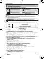
Safety Precautions
Safety Precautions
To prevent injury to the user or other people and property damage, the following instructions must be
followed.
n Incorrect operation due to ignoring instruction will cause harm or damage. The seriousness is
classified by the following indications.
The following symbols are displayed on indoor and outdoor units.
n Meanings of symbols used in this manual are as shown below.
This symbol indicates the possibility of death or serious injury.
This symbol indicates the possibility of injury or damage to properties only.
Be sure not to do.
Be sure to follow the instruction.
Installation
• Compliance with national gas regulations shall be observed.
• Do not use a defective or underrated circuit breaker. Use this appliance
on a dedicated circuit.
- There is risk of fire or electric shock.
• For electrical work, contact the dealer, seller, a qualified electrician, or
an Authorized Service Center.
- Do not disassemble or repair the product. There is risk of fire or
electric shock.
• Always ground the product.
- There is risk of fire or electric shock.
• Install the panel and the cover of control box securely.
- There is risk of fire or electric shock.
• Always install a dedicated circuit and breaker.
- Improper wiring or installation may cause fire or electric shock.
• Use the correctly rated breaker or fuse.
- There is risk of fire or electric shock.
• Do not modify or extend the power cable.
- There is risk of fire or electric shock.
Read the precautions in this manual
carefully before operating the unit.
This appliance is filled with flammable
refrigerant (R32)
This symbol indicates that the Operation
Manual should be read carefully.
This symbol indicates that a service
personnel should be handling this
equipment with reference to the
Installation Manual.
WARNING
CAUTION
!
!
WARNING
!

Installation Manual 5
Safety Precautions
ENGLISH
• Do not install, remove, or re-install the unit by yourself (customer).
- There is risk of fire, electric shock, explosion, or injury.
• Be cautious when unpacking and installing the product.
- Sharp edges could cause injury. Be especially careful of the case
edges and the fins on the condenser and evaporator.
• For installation, always contact the dealer or an Authorized Service
Center.
- There is risk of fire, electric shock, explosion, or injury.
• Do not install the product on a defective installation stand.
- It may cause injury, accident, or damage to the product.
• Be sure the installation area does not deteriorate with age.
- If the base collapses, the air conditioner could fall with it, causing
property damage, product failure, and personal injury.
• Do not turn on the breaker or power under condition that front panel,
cabinet, top cover, control box cover are removed or opened.
- Otherwise, it may cause fire, electric shock, explosion or death.
• Use a vacuum pump or Inert (nitrogen) gas when doing leakage test or
air purge. Do not compress air or Oxygen and Do not use Flammable
gases. Otherwise, it may cause fire or explosion.
- There is the risk of death, injury, fire or explosion.
•
Have all electric work done by a licensed electrician according to "Electric
Facility Engineering Standard" and "Interior Wire Regulations" and the
instructions given in this manual and always use a special circuit.
- If the power source capacity is inadequate or electric work is
performed improperly, electric shock or fire may result.
• Always intstall a dedicated circuit and breaker.
- Improper wiring or installation may cause fire or electric shock.
• The appliance shall be stored in a well-ventilated area where the room
size corresponds to the room area as specified for operation. (for R32)
• The appliance shall be stored in a room without continuously operating
ignition sources (for example: open flames, an operating gas appliance
or an operating electric heater.)
• Keep any required ventilation openings clear of obstruction.
• Mechanical connections shall be accessible for maintenance purposes.
• To prevent the mixing of different types of refrigerants, be sure to check
the type of refrigerant used in the outdoor unit.
Operation
• Do not let the air conditioner run for a long time when the humidity is
very high and a door or a window is left open.
- Moisture may condense and wet or damage furniture.

6 Indoor Unit
Safety Precautions
• Take care to ensure that power cable could not be pulled out or
damaged during operation.
- There is risk of fire or electric shock.
• Do not place anything on the power cable.
- There is risk of fire or electric shock.
• Do not plug or unplug the power supply plug during operation.
- There is risk of fire or electric shock.
• Do not touch(operate) the product with wet hands.
- There is risk of fire or electrical shock.
• Do not place a heater or other appliances near the power cable.
- There is risk of fire and electric shock.
• Do not allow water to run into electric parts.
- There is risk of fire, failure of the product, or electric shock.
• Do not store or use flammable gas or combustibles near the product.
- There is risk of fire or failure of product.
• Do not use the product in a tightly closed space for a long time.
- Oxygen deficiency could occur.
• When flammable gas leaks, turn off the gas and open a window for
ventilation before turn the product on.
- Do not use the telephone or turn switches on or off. There is risk of
explosion or fire.
• If strange sounds, smell or smoke comes from product. Turn the
breaker off or disconnect the power supply cable.
- There is risk of electric shock or fire.
• Stop operation and close the window in storm or hurricane.
If possible, remove the product from the window before the hurricane
arrives.
- There is risk of property damage, failure of product, or electric shock.
• Do not open the inlet grill of the product during operation.
(Do not touch the electrostatic filter, if the unit is so equipped.)
- There is risk of physical injury, electric shock, or product failure.
• When the product is soaked (flooded or submerged), contact an
Authorized Service Center.
- There is risk of fire or electric shock.
• Be cautious that water could not enter the product.
- There is risk of fire, electric shock, or product damage.
• Ventilate the product from time to time when operating it together with a
stove, etc.
- There is risk of fire or electric shock.
• Turn the main power off when cleaning or maintaining the product.
- There is risk of electric shock.

Installation Manual 7
Safety Precautions
ENGLISH
• When the product is not be used for a long time, disconnect the power
supply plug or turn off the breaker.
- There is risk of product damage or failure, or unintended operation.
• Take care to ensure that nobody could step on or fall onto the outdoor
unit.
- This could result in personal injury and product damage.
• When mechanical connectors are reused indoors, sealing parts shall
be renewed. (for R32)
• When flared joints are reused indoors, the flare part shall be re-
fabricated. (for R32)
• Periodic ( more than once/year ) cleaning of the dust or salt particles
stuck on the heat exchanger by using water.
• Do not use means to accelerate the defrosting process or to clean,
other than those recommended by the manufacturer.
• Do not pierce or burn refrigerant cycle part.
• Be aware that refrigerants may not contain an odour.
Installation
• Always check for gas (refrigerant) leakage after installation or repair of
product.
- Low refrigerant levels may cause failure of product.
• Install the drain hose to ensure that water is drained away properly.
- A bad connection may cause water leakage.
• Keep level even when installing the product.
- To avoid vibration or water leakage.
• Do not install the product where the noise or hot air from the outdoor
unit could damage the neighborhoods.
- It may cause a problem for your neighbors.
• Use two or more people to lift and transport the product.
- Avoid personal injury.
• Do not install the product where it will be exposed to sea wind (salt
spray) directly.
- It may cause corrosion on the product. Corrosion, particularly on the
condenser and evaporator fins, could cause product malfunction or
inefficient operation.
CAUTION
!

8 Indoor Unit
Safety Precautions
• Any person who is involved with working on or breaking into a
refrigerant circuit should hold a current valid certificate from an industry-
accredited assessment authority, which authorises their competence to
handle refrigerants safely in accordance with an industry recognised
assessment specification. (for R32)
• The appliance shall be stored so as to prevent mechanical damage
from occurring.
• Refrigerant tubing shall be protected or enclosed to avoid damage.
• Flexible refrigerant connectors (such as connecting lines between the
indoor and outdoor unit) that may be displaced during normal
operations shall be protected against mechanical damage.
• The installation of pipe-work shall be kept to a minimum.
• Pipe-work shall be protected from physical damage.
• A brazed, welded, or mechanical connection shall be made before
opening the valves to permit refrigerant to flow between the
refrigerating system parts.
• Dismantling the unit, treatment of the refrigerant oil and eventual parts
should be done in accordance with local and national standards.
Operation
• Do not expose the skin directly to cool air for long periods of time.
(Don't sit in the draft.)
- This could harm to your health.
• Do not use the product for special purposes, such as preserving foods,
works of art, etc. It is a consumer air conditioner, not a precision
refrigeration system.
- There is risk of damage or loss of property.
• Do not block the inlet or outlet of air flow.
- It may cause product failure.
• Use a soft cloth to clean. Do not use harsh detergents, solvents, etc.
- There is risk of fire, electric shock, or damage to the plastic parts of
the product.
• Do not touch the metal parts of the product when removing the air filter.
They are very sharp!
- There is risk of personal injury.
• Do not step on or put anything on the product. (outdoor units)
- There is risk of personal injury and failure of product.
• Always insert the filter securely. Clean the filter every two weeks or
more often if necessary.
- A dirty filter reduces the efficiency of the air conditioner and could
cause product malfunction or damage.

Installation Manual 9
Safety Precautions
ENGLISH
• Do not insert hands or other objects through the air inlet or outlet while
the product is operated.
- There are sharp and moving parts that could cause personal injury.
• Do not drink the water drained from the product.
- It is not sanitary and could cause serious health issues.
• Use a firm stool or ladder when cleaning or maintaining the product.
- Be careful and avoid personal injury.
• Replace the all batteries in the remote control with new ones of the
same type. Do not mix old and new batteries or different types of
batteries.
- There is risk of fire or explosion.
• Do not recharge or disassemble the batteries. Do not dispose of
batteries in a fire.
- They may burn or explode.
• If the liquid from the batteries gets onto your skin or clothes, wash it
well with clean water. Do not use the remote if the batteries have
leaked.
- The chemicals in batteries could cause burns or other health hazards.
• If you eat the liquid from the batteries, brush your teeth and see doctor.
Do not use the remote if the batteries have leaked.
- The chemicals in batteries could cause burns or other health hazards.
• Servicing shall only be performed as recommended by the equipment
manufacturer. Maintenance and repair requiring the assistance of other
skilled personnel shall be carried out under the supervision of the
person competent in the use of flammable refrigerants. (for R32)
• Means for disconnection must be incorporated in the fixed wiring in
accordance with the wiring rules.
• If the supply cord is damaged, it must be replaced by the manufacturer,
its service agent or similarly qualified persons in order to avoid a
hazard.

10 Indoor Unit
Installation
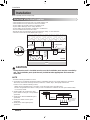
• There should not be any heat source or steam near the unit.
• There should not be any obstacles to the air circulation.
• A place where air circulation in the room will be good.
• A place where drainage can be easily obtained.
• A place where noise prevention is taken into consideration.
• Do not install the unit near the door way.
• Ensure the spaces indicated by arrows from the wall, ceiling, or other obstacles.
• The indoor unit must have the maintenance space.
Read completely, then follow step by step.
Unit:mm
Ceiling
Ceiling board
Ceiling board
200 or more
Above 1 800
3 300 or less
1 000
or more
500 or
more
500 or
more
300 or less
10 or more
20 ±3
Floor
Floor
Floor
Selection of the Best Location
NOTE
• Avoid the following installation location.
1. Such places as restaurants and kitchen where considerable amount of oil steam and flour is generated.
These may cause heat exchange efficiency reduction, or water drops, drain pump mal-function.
In these cases, take the following actions;
• Make sure that ventilation fan is enough to cover all noxious gases from this place.
• Ensure enough distance from the cooking room to install the air conditioner in such a place where it may
not suck oily steam.
2. Avoid installng air conditioner in such
places where cooking oil or iron powder is
generated.
3. Avoid places where inflammable gas is
generated.
4. Avoid place where noxious gas is
generated.
5. Avoid places near high frequency
generators.
Use the ventilation fan
for smoke-collecting
hood with sufficient
capacity.
Cooking table
Air conditioner
Take enough
distance
Installation
CAUTION
In case that the unit is installed near the sea, the installation parts may be corroded by
salt. The installation parts (and the unit) should be taken appropriate anti-corrosion
measures.
!

Installation Manual 11
Installation
ENGLISH
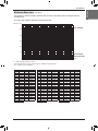
- The appliance shall be installed, operated and stored in a room with a floor area larger than the
minimum area.
- Use the graph of table to determine the minimum area.
- m : Total refrigerant amount in the system
- Total refrigerant amount : factory refrigerant charge + additional refrigerant amount
- Amin : minimum area for installation
Minimum floor area
0
100
200
300
400
500
600
Amin (m
2
)
m (kg)
0 1.224 2 3 4 5 6 7 8
Floor standing
Wall mounted
Ceiling mounted
Floor location
m (kg) Amin (m
2
)
< 1.224
-
1.224
12.9
1.4 16.82
1.6 21.97
1.8 27.80
2 34.32
2.2 41.53
2.4 49.42
2.6 58.00
2.8 67.27
3 77.22
3.2 87.86
3.4 99.19
3.6 111.20
3.8 123.90
4 137.29
4.2 151.36
4.4 166.12
Floor location
m (kg) Amin (m
2
)
4.6 181.56
4.8 197.70
5 214.51
5.2 232.02
5.4 250.21
5.6 269.09
5.8 288.65
6 308.90
6.2 329.84
6.4 351.46
6.6 373.77
6.8 396.76
7 420.45
7.2 444.81
7.4 469.87
7.6 495.61
7.8 522.04
Wall mounted
m (kg) Amin (m
2
)
< 1.224
-
1.224
1.43
1.4 1.87
1.6 2.44
1.8 3.09
2 3.81
2.2 4.61
2.4 5.49
2.6 6.44
2.8 7.47
3 8.58
3.2 9.76
3.4 11.02
3.6 12.36
3.8 13.77
4 15.25
4.2 16.82
4.4 18.46
Wall mounted
m (kg) Amin (m
2
)
4.6 20.17
4.8 21.97
5 23.83
5.2 25.78
5.4 27.80
5.6 29.90
5.8 32.07
6 34.32
6.2 36.65
6.4 39.05
6.6 41.53
6.8 44.08
7 46.72
7.2 49.42
7.4 52.21
7.6 55.07
7.8 58.00
Ceiling Mounted
m (kg) Amin (m
2
)
< 1.224
-
1.224
0.956
1.4 1.25
1.6 1.63
1.8 2.07
2 2.55
2.2 3.09
2.4 3.68
2.6 4.31
2.8 5.00
3 5.74
3.2 6.54
3.4 7.38
3.6 8.27
3.8 9.22
4 10.21
4.2 11.26
4.4 12.36
Ceiling Mounted
m (kg) Amin (m
2
)
4.6 13.50
4.8 14.70
5 15.96
5.2 17.26
5.4 18.61
5.6 20.01
5.8 21.47
6 22.98
6.2 24.53
6.4 26.14
6.6 27.80
6.8 29.51
7 31.27
7.2 33.09
7.4 34.95
7.6 36.86
7.8 38.83
(for R32)

12 Indoor Unit
Installation
Ceiling Dimension and Hanging Bolt Location
Level gauge
Ceiling
(Unit: mm)
TT Chassis
TU Chassis
1 285(Hanging bolt)
1 385(Ceiling opening)
50
250
600
50
466
(Ceiling opening)
1 180
448
600
250
965(Hanging bolt)
1 065(Ceiling opening)
50
50
860
448
306
400 4040
400 4040
306
354
(Hanging bolt)
466
(Ceiling opening)
354
(Hanging bolt)
Ceiling board
• The dimensions of the paper model for installation are the same as those of the ceiling opening dimensions.
Set screw of
paper model (4 pieces)
Paper model
for installation
Ceiling board
70 mm
Adjust the same height
Ceiling board
Ceiling
Flat washer for M10
(accessory)
Keep the length of the bolt
from the bracket to 40 mm
Open the ceiling board
along the outer edge of the
paper model
Flat washer for M10
(accessory)
Hanging bolt
(W3/8 or M10)
Nut
(W3/8 or M10)
Nut
(W3/8 or M10)
Spring washer
(M10)
Air conditioner body
• The following parts are local purchasing.
① Hanging bolt - W 3/8 or M10
② Nut - W 3/8 or M10
③ Spring washer - M10
④ Plate washer - M10
• The following parts are local purchasing.
① Hanging bolt - W 3/8 or M10
② Nut - W 3/8 or M10
③ Spring washer - M10
④ Plate washer - M10
CAUTION
Tighten the nut and bolt to prevent unit
from falling off.
!
CAUTION
• This air-conditioner uses a drain pump.
• Install the unit horizontally using a level
gauge.
• During the installation, care should be
taken not to damage electric wires.
• Select and mark the position for fixing bolts
and piping hole.
• Decide the position for fixing bolts slightly
tilted to the drain direction after considering
the direction of drain hose.
• Drill the hole for anchor bolt on the wall.
!
CAUTION
• When mechanical connectors are reused indoors, sealing parts shall be renewed. (for R32)
• When flared joints are reused indoors, the flare part shall be re-fabricated. (for R32)
!

Installation Manual 13
ENGLISH
Installation
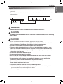
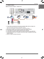
Terminal Block Indoor
1(L) 2(N) 3 4
INDOOR
POWER INPUT
A ----BABAB
GND 12 V
DRY2DRY1
INTERNET
Terminal Block of outdoor unit
IDUSODU
Outdoor
Unit
• Connect the wires to the terminals on the control board individually according to the outdoor unit
connection.
• Ensure that the color of the wires of outdoor unit and the terminal No. are the same as those of indoor
unit respectively.
Wiring Connection
WARNING
Make sure that the screws of the terminal are free from looseness.
!
CAUTION
The Power cord connected to the unit should be selected according to the following
specifications.
!
CAUTION
After the confirmation of the above conditions, prepare the wiring as follows:
1) Never fail to have separate power specially for the air conditioner. As for the method of
wiring, follow the circuit diagram pasted on the inside of control box cover.
2) Provide a circuit breaker switch between power source and the unit.
3) The screw which fasten the wiring in the casing of electrical fittings are liable to come
loose from vibrations to which the unit is subjected during the course of transportation.
Check them and make sure that they are all tightly fastened. (If they are loose, it could give
rise to burn-out of the wires.)
4) Confirm the Specification of power source
5) Confirm that electrical capacity is sufficient.
6) Be sure that the starting voltage is maintained at more than 90 % of the rated voltage
marked on the name plate.
7) Confirm that the cable thickness is as specified in the power sources specification.
(Particularly note the relation between cable length and thickness.)
8) Do not install the leakage breaker in a place which is wet or moist.
Water or moist may cause short circuit.
9) The following troubles would be caused by voltage drop-down.
• Vibration of a magnetic switch, damage on the contact point there of, fuse breaking, disturbance
to the normal function of a overload protection device.
• Proper starting power is not given to the compressor.
!

14 Indoor Unit
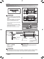
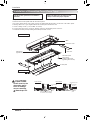
1. Open the air outlet vane, and extract side covers.
2. Remove the air inlet panel from the decoration panel.
3.
Hook decoration panel to indoor unit, using hooks attached at the backside of both side of decoration panel.
4. Arrange wires not to get caught between decoration panel and indoor unit.
5. Screw 7 fixing screws. (7, 9, 12 kBtu : 6 screws)
6. Connect the vane motor connector ,display connector and air inlet panel connector.
7. Install the air inlet panel (including the air filter) and side covers.
Air conditioner unit
Decorative panel
Side cover
Decorative panel
fixing screws
(hexagon M6 screws)
(tightening about 20 mm)
Air inlet panel
Air outlet vane
Plasma filter
(applied only to plasma model)
Mesh
Control box cover
The decoration panel has its installation
direction.
Before installing the decoration panel,
always remove the paper template.
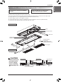
Air conditioner
unit
Ceiling
board
Decoration panel
Decoration
panel
Fit the insulator (this part) and
be careful for cool air leakage
Good example
Air
Cool air leakage
(no good)
Bad example
Ceiling
board
Air conditioner unit
Installation of Decoration Panel (Panel Type)
Installation
CAUTION
Install certainly the
decoration panel.
Cool air leakage
causes sweating.
Waterdrops fall.
!

Installation Manual 15
ENGLISH
Installation
1. Open the air outlet vane, and extract side covers.
2. Remove the air inlet grille from the decoration panel.
3.
Hook decoration panel to indoor unit, using hooks attached at the backside of both side of decoration panel.
4. Arrange wires not to get caught between decoration panel and indoor unit.
5. Screw 7 fixing screws. (7, 9, 12 kBtu : 6 screws)
6. Connect the vane motor connector and display connector. (Plasma connector for plasma model)
7. Install the air inlet grille (including the air filter) and side covers.
Air conditioner unit
Decorative panel
Plasma filter
(applied only to plasma model)
Mesh
Control box cover
Decorative panel
fixing screws
(hexagon M6 screws)
(tightening about 20 mm)
Side cover
Air inlet grille
Air outlet vane
The decoration panel has its installation
direction.
Before installing the decoration panel,
always remove the paper template.
Air conditioner
unit
Ceiling
board
Decoration panel
Decoration
panel
Fit the insulator (this part) and
be careful for cool air leakage
Good example
Air
Cool air leakage
(no good)
Bad example
Ceiling
board
Air conditioner unit
Installation of Decoration Panel (Grille Type)
CAUTION
Install certainly the
decoration panel.
Cool air leakage
causes sweating.
Waterdrops fall.
!

16 Indoor Unit
• Drain piping must have down-slope (1/50 to 1/100): be sure not to
provide up-and-down slope to prevent reversal flow.
• During drain piping connection, be careful not to exert extra force
on the drain port on the indoor unit.
• The outside diameter of the drain connection on the indoor unit is
32 mm.
•
Be sure to install heat insulation on the drain piping.
Piping material: Polyvinyl chloride pipe VP-25 and
pipe fittings.
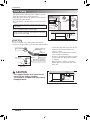
The air conditioner uses a drain pump to drain water.
Use the following procedure to test the drain pump operation:
• Connect the main drain pipe to the exterior
and leave it provisionally until the test
comes to an end.
• Feed water to the flexible drain hose and
check the piping for leakage.
• Be sure to check the drain pump for normal
operating and noise when electrical wiring
is complete.
• When the test is complete, connect the
flexible drain hose to the drain port on the
indoor unit.
Heat insulation material: Polyethylene foam with
thickness more than 8 mm.
Drain Test
Maintenance
drain port
Upward
routing
not allowed
Pipe clamp
Indoor unit
1/50~1/100
Max 700 mm
Feed water
Drain pump
Drain pan
Flexible drain hose
(accessory)
Main
drain pipe
Glue the joint
Drain
port
Drain hose connection
Use the clip (accessory)
1/50~1/100 slope
Hanger
distance
Hanger bracket
Max 700 mm
Flexible drain hose
Insulation
Metal
clamp
Max 300 mm
1~15 m
Drain Piping
Installation
CAUTION
The supplied flexible drain hose should
not be curved, neither screwed.
The curved or screwed hose may cause a
leakage of water.
!

Installation Manual 17
ENGLISH
Installation
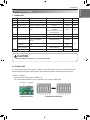
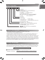
DIP Switch Setting
Function Description Setting Off Setting On Default
SW1
SW2
SW3
SW4
SW5
SW6
SW7
SW8
Communication
Cycle
Group Control
Dry Contact Mode
Installation
Heater linkage
Ventilator linkage
Vane selection
(Console)
Region selection
Etc.
N/A (Default)
N/A (Default)
Selection of Master or Slave
Selection of Dry Contact
Mode
Fan continuous operation
N/A
Selection of Ventilator
linkage
Selection of up/down side
Vane
Selection tropical region
Spare
-
-
Master
Wired/Wireless remote
controller
Selection of Manual or Auto
operation Mode
Continuous operation Removall
-
Linkage Removal
Up side + Down side Vane
General model
-
-
-
Slave
Auto
-
-
Working
Up side Vane
Only
Tropical model
-
Off
Off
Off
Off
Off
Off
Off
Off
2. Outdoor Unit
1. Indoor Unit
In case that the products meet specific conditions, “Auto addressing” function can start automatically
with the improved speed by turning the DIP switch #3 of the outdoor unit and resetting the power.
* Specific conditions:
- All names of the indoor units are ARNU****4.
- The serial number of Multi V super IV (outdoor units) is after October 2013.
DIP switch 7 segment
Outdoor Unit PCB Outdoor Unit DIP Switch
CAUTION
For Multi V Models, DIP switch 1, 2, 6, 8 must be set OFF.
!

18 Indoor Unit
Installation
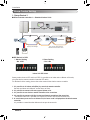
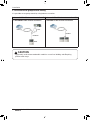
Group Control Setting
GND
Signal
12 V
Master Slave Slave Slave
Display Error Message
Only connect serial signal and
GND lines between indoor units.
or
LGAP Network System
Master
1. Group Control 1
n Wired remote controller 1 + Standard Indoor Units
Some products have no DIP switch on PCB. It is possible to set indoor units to Master or Slave by
using the wireless remote controller instead of DIP switch.
For the details of the setting, please refer to the manual of the wireless remote controller.
1. It is possible to 16 indoor units(Max.) by one wired remote controller.
Set only one indoor unit to Master, set the others to Slave.
2. It is possible to connect with every type of indoor units.
3. It is possible to use wireless remote controller at the same time.
4. It is possible to connect with Dry Contact and Central controller at the same time.
- The Master indoor unit is possible to recognize Dry Contact and Central Controller only.
5. In case that any error occurs at indoor unit, the error code is displayed on the wired remote
controller.
It is possible to control the other indoor units except the error units.
n DIP Switch in PCB
¿ Master Setting
- No. 3 Off
¡ Slave Setting
- No. 3 On
Indoor Unit DIP Switch

Installation Manual 19
ENGLISH
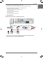
Installation
GND
Signal
12 V
Slave
Slave
Master
or
Donʼt connect serial 12 V line
LGAP Network System
Master
MasterMaster
Display Error Message
h It is possible to connect indoor units since Feb. 2009.
h It can be the cause of malfuctions when there is no setting of master and slave.
h In case of Group Control, it is possible to use following functions.
- Selection of operation, stop or mode
- Temperature setting and room temperature check
- Current time change
- Control of flow rate (High/Middle/Low)
- Reservation settings
It is not possible to use some functions.
h It is possible to control 16 indoor units(Max.) with the master wired remote control.
h Other than those, it is same with the Group Control 1.
2. Group Control 2
n Wired remote controllers + Standard Indoor Units

20 Indoor Unit
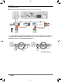
Installation
GND
Signal
12 V
LGAP Network System
FAU
Master
FAU
or
Slave
Master
Slave
Master
Master
Display Error Message
Display Error Message
N
M
FAU
Standard
FAU FAU
Standard
FAU
* FAU : Fresh Air Intake Unit
Standard: Standard Indoor Unit
Standard Standard
h In case of connecting with standard indoor unit and Fresh Air Intake Unit, separate Fresh
Air Intake Unit with standard units. (N, M ≤ 16) (Because setting temperature are different.)
h Other than those, it is same with Group Control 1.
3. Group Control 3
n Mixture connection with indoor units and Fresh Air Intake Unit
Page is loading ...
Page is loading ...
Page is loading ...
Page is loading ...
Page is loading ...
-
 1
1
-
 2
2
-
 3
3
-
 4
4
-
 5
5
-
 6
6
-
 7
7
-
 8
8
-
 9
9
-
 10
10
-
 11
11
-
 12
12
-
 13
13
-
 14
14
-
 15
15
-
 16
16
-
 17
17
-
 18
18
-
 19
19
-
 20
20
-
 21
21
-
 22
22
-
 23
23
-
 24
24
-
 25
25


Ask a question and I''ll find the answer in the document
Finding information in a document is now easier with AI
Related papers
-
LG ARNU18GTLC4.ENWBUAE Installation guide
-
LG ARNU09GTLC4.ENWBLEU User manual
-
LG ARNU24GTLA4.ENWBEVH Owner's manual
-
LG ARNU18GTLA4.ANWALAP Installation guide
-
-
LG ARNU07GCEU4 Installation guide
-
LG ARNU24GTSC4.ENWBLEU Installation guide
-
LG ARNU24GTSA4 Installation guide
-
-
LG ARNU24GCFU4 Installation guide
