NEC Diamond Pro 730 Owner's manual

Category
TVs & monitors
Type
Owner's manual

NEC Diamond Pro 730: This high-resolution color monitor boasts a 43cm/17" screen with a maximum addressable resolution of 1600x1200. Compatible with both PC and Macintosh platforms, it provides sharp text and vivid color graphics. Its auto-scanning capability allows for easy upgrading of video cards or software. With On Screen Display (OSD) of all monitor set-up and adjustment functions, it's user-friendly and easy to operate.

NEC Diamond Pro 730: This high-resolution color monitor boasts a 43cm/17" screen with a maximum addressable resolution of 1600x1200. Compatible with both PC and Macintosh platforms, it provides sharp text and vivid color graphics. Its auto-scanning capability allows for easy upgrading of video cards or software. With On Screen Display (OSD) of all monitor set-up and adjustment functions, it's user-friendly and easy to operate.

- 1-1 -
ENGLISH
CAUTION
The power cord provided with this monitor is de-
signed for safety and must be used with a properly
grounded outlet to avoid possible electrical shock.
Do not remove the monitor cabinet as this can
expose you to very high voltages and other hazards.
Trademark
IBM, PC, PS/2, PS/V, Personal System/2 are registered trade-
marks of International Business Machines Corp.
Apple Macintosh is a registered trademark of Apple Computer, Inc.
Quadra is a trademark of Apple Computer, Inc.
UNIX is a registered trademark in the United States and other
countries, licensed exclusively through X/Open Company Limited.
ENERGY STAR
is a U.S. registered mark.
© 2001 NEC-Mitsubishi Electric Visual Systems Corporation
1. INTRODUCTION ..................................................... 1-2
1.1 Features ........................................................ 1-2
1.2 Internal Preset Memory Capability ................ 1-3
1.3 Power Management Function ....................... 1-3
1.4 DDC .............................................................. 1-3
1.5 Location Considerations ............................... 1-3
1.6 Cleaning Your Monitor .................................. 1-3
1.7 Unpacking ..................................................... 1-4
1.8 Tilt/Swivel Base............................................. 1-4
Screen Position Adjustment .......................... 1-4
1.9 Quick Operation Chart .................................. 1-4
2. PART NAME............................................................ 1-5
2.1 Control Names .............................................. 1-5
2.2 Function ........................................................ 1-5
3. INSTALLATION AND CONNECTION ..................... 1-6
3.1 AC Power Connection................................... 1-6
3.2 Signal Cable Connection .............................. 1-6
3.2.1 Connecting to any IBM VGA Compatible
System ................................................... 1-6
3.2.2 Connecting to an Apple Macintosh
Computer ............................................... 1-6
4. OSD(On Screen Display) FUNCTIONS .................. 1-7
4.1 How to adjust the screen .............................. 1-7
4.2 Adjustment Items .......................................... 1-8
5. TROUBLESHOOTING ............................................ 1-10
6. SPECIFICATIONS................................................... 1-12
7. APPENDIX .............................................................. 1-13
7.1
Optional Macintosh Adapter AD-A205 settings .
1-13
CONTENTS
MANUFACTURER DECLARATION FOR CE-MARK-
ING:
We, NEC-Mitsubishi Electric Visual Systems Corpo-
ration, declare under our sole responsibility, that this
product is in conformity with the following standards:
EN60950
EN55022 Class B
EN61000-3-2
EN61000-3-3
EN55024
following the provisions of:
73/23/EEC Low Voltage Directive
89/336/EEC EMC Directive
WARNING!
This product is not designed for use in life support
devices and NEC-Mitsubishi Electronics Display makes
no representations to the contrary. Life support devices
are those devices which are used to measure, diagnose,
or evaluate the tissue, systems or functions of the
human body; or other devices employed to support or
sustain life or good health.
01.8.9, 10:37 AMPage 1
- 1-2 -
1
1
INTRODUCTION
Congratulations on your purchase of the high resolution
color monitor. We designed this monitor to provide you
with years of reliable trouble-free operation.
This guide tells you how to connect, adjust and care for your
monitor. This guide also provides technical specifications
and instructions for troubleshooting any basic problems
you may experience with your monitor.
1.1 Features
This monitor is a 43cm/17"(41cm/16" Diagonal Viewable
Image) intelligent, microprocessor-based monitor compat-
ible with most analog RGB (Red, Green, Blue) display
standards.
It provides crisp text and vivid color graphics with both PC
and Macintosh platforms.
The monitor’s wide auto-scanning compatibility range
makes it possible to upgrade video cards or software
without purchasing a new monitor.
Digitally controlled auto-scanning is done using an
internal microprocessor, for horizontal scan frequen-
cies between 31kHz and 96kHz, and vertical scan
frequencies between 55Hz and 160Hz. The micropro-
cessor-based intelligence allows the monitor to oper-
ate in each frequency mode with the precision of a fixed
frequency monitor.
The monitor contains resident memory for pre-pro-
grammed screen display standards and is also capable
of storing additional user adjustment parameters.
The monitor is capable of producing a non-interlaced
maximum addressable resolution format of 1600 dots
x 1200 lines. This display is well suited for windowing
environments.
Because of the analog signal inputs, the monitor can
display an unlimited palette of colors that can be
manually adjusted to suit your specific needs.
The monitor has a power management function ac-
corded to VESA
TM
-DPMS
TM
-standard. To save energy,
the monitor must be connected to a system compliant
with the VESA
TM
-DPMS
TM
-standard. (Refer to your
computer and/or video card instructions for proper
operation.)
To ensure ease of installation and ongoing use, the
monitor features On Screen Display (OSD) of all moni-
tor set-up and adjustment functions.
For use in a variety of applications, the monitor com-
plies with UL 1950, CSA C22.2 No.950-95 and EN60950
for safety, FCC Class-B and EN55022 Class-B for EMI,
pr EN50279 (MPR-III), ISO 9241-3, ISO9241-7 and
ISO9241-8 for ergonomics. The monitor also complies
with TCO’99 guideline for environmental safe use.
The monitor features the world's standard
DIAMONDTRON NF CRT upgraded with improved
focus and convergence for supersharp and pure pic-
ture images.
The monitor complies with Video Electronics Standards
Association (VESA
TM
) DDC
TM
1/2B(EDID) specification.
If your computer is Plug & Play compliant setup will be
done automatically.
The CRT provides fine 0.25mm aperture grille pitch/
Maximum addressable resolution of 1600x1200.
The monitor has a contrast enhancement function
(FPM: Fine Picture Mode) and it is to accentuate
pictures and graphical images.
01.8.9, 10:37 AMPage 2
- 1-3 -
ENGLISH
1.3 Power Management Function
The monitor has a power management function which
reduces the power consumption of the monitor when not
in use.
The power saving mode is invoked by a VESA DPMS-
compliant computer. Check your computer's manual for
setting this function.
1.4 DDC
The monitor includes the VESA DDC™ 1 and DDC™ 2B
feature. DDC (Display Data Channel) is a communication
channel over which the monitor automatically informs the
computer system about its capabilities (e.g. each sup-
ported resolution with its corresponding timing).
DDC is routed through previously unused pins of the 15-pin
VGA connector.
The system will “Plug and Play” if both monitor and com-
puter implement the DDC protocol.
CAUTION
1.5 Location Considerations
When setting up and using the monitor, keep the following
in mind:
For optimum viewing, avoid placing the monitor
against a bright background or where sunlight or
other light sources may reflect on the display area of
the monitor. Place the monitor just below eye level.
Place the monitor away from strong magnetic or
electromagnetic fields, such as high capacity trans-
formers, electric motors, large current power lines,
steel pillars, etc....
Magnetism can cause distortion in the picture and/or
color purity.
Avoid covering the slots or openings of the monitor.
Allow adequate ventilation around the monitor so the
heat from the monitor can properly dissipate. Avoid
putting the monitor into any enclosure that does not
have adequate ventilation.
Avoid exposing the monitor to rain, excessive mois-
ture, or dust, as this can cause a fire or shock hazard.
Avoid placing the monitor, or any other heavy object,
on the power cord. Damage to the power cord can
cause a fire or electrical shock.
When transporting the monitor, handle it with care.
1.6 Cleaning Your Monitor
When cleaning the monitor, please follow these guidelines:
Always unplug the monitor before cleaning.
Wipe the screen and cabinet front and sides with a
soft cloth.
If the screen requires more than dusting, apply a
household window cleaner to a soft cloth to clean
the monitor screen.
Do not use benzene, thinner or any volatile sub-
stances to clean the unit as the finish may be
permanently marked.
Never leave the monitor in contact with rubber or
vinyl for an extended time period.
Do not spray directly on the screen as cleaner may
drip into the monitor and damage the circuitry.
Never use an abrasive cleaner on the screen sur-
face as this will damage the anti-reflection coating.
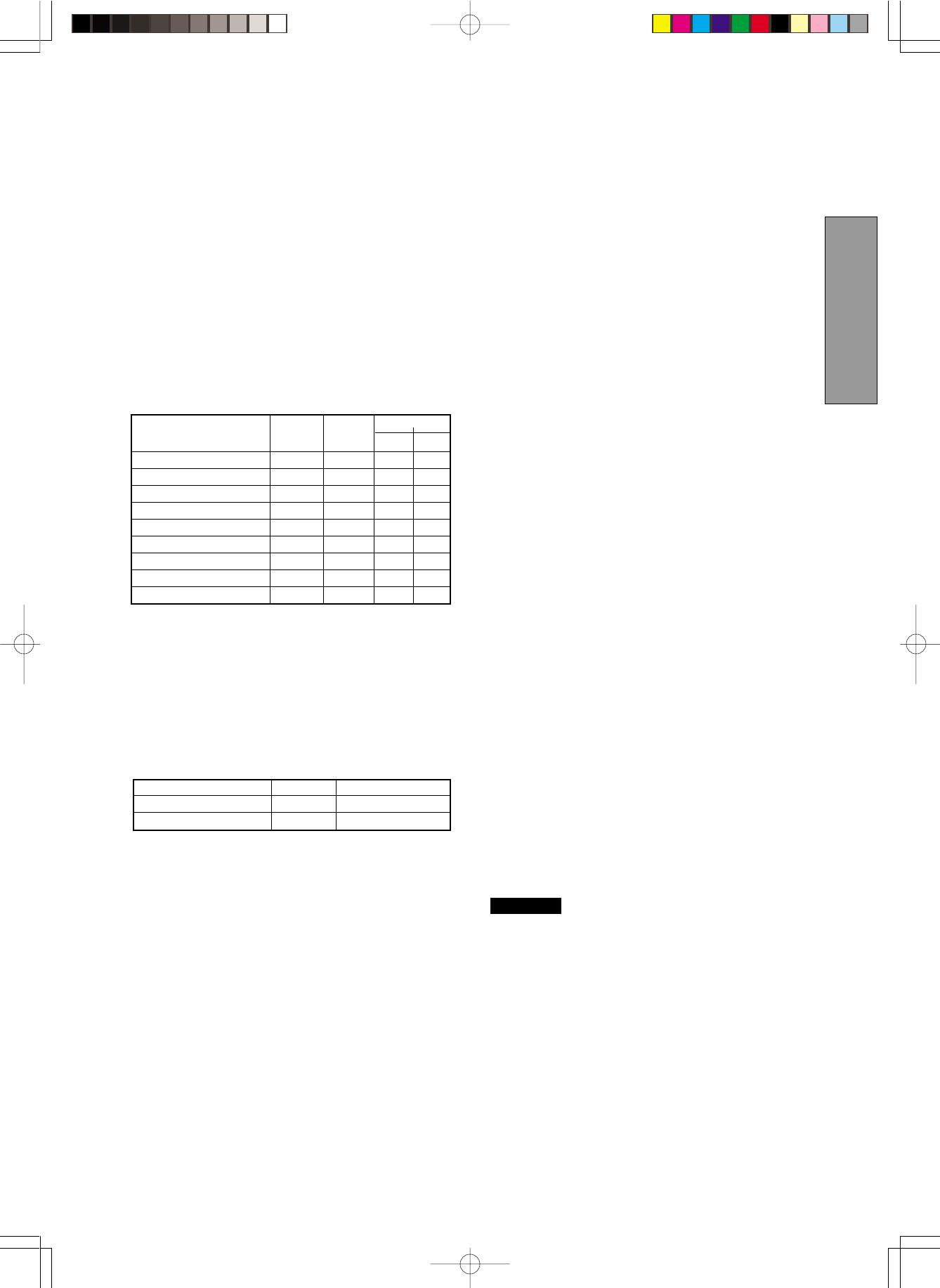
Mode Power Power-On Indicator
Normal 96 W Green
Power Saving Mode 5 W Orange
PRESET Polarity
TIMING Fh(kHz) Fv (Hz) H V
640 x 480 N.I. 31.5 59.9
640 x 480 N.I. 37.5 75.0
800 x 600 N.I. 46.9 75.0 + +
800 x 600 N.I. 53.7 85.0 + +
1024 x 768 N.I. 60.0 75.0 + +
1024 x 768 N.I. 68.7 85.0 + +
1280 x 1024 N.I. 80.0 75.0 + +
1280 x 1024 N.I. 91.1 85.0 + +
1600 x 1200 N.I. 93.8 75.0 + +
1.2 Internal Preset Memory Capability
To minimize adjustment needs, the factory has preset
popular display standards into the monitor, as shown in
Table 1. If any of these display standards are detected, the
picture size and position are automatically adjusted. All of
the factory presets may be overwritten by adjusting the user
controls. This monitor is capable of automatically storing up
to 16 additional display standards. The new display infor-
mation must differ from any of the existing display stan-
dards by at least 1kHz for the horizontal scan frequency or
5Hz for the vertical scan frequency or the sync signal
polarities must be different.
Table 1. Memory Buffer Factory Presets
01.8.9, 10:37 AMPage 3
- 1-4 -
Connect the color monitor and computer with
the necessary cords and cables.
1.9 Quick Operation Chart
To summarize the steps in connecting your computer
with the color monitor and setting the necessary controls
and switches, refer to the chart below.
See
Section 3. INSTALLATION AND CONNECTION
Turn on the computer.
Turn on the color monitor.
Set the controls.
See
Section 4. OSD(On Screen
Display) FUNCTIONS
If a problem appears.
If the problem persists.
Call for your authorized Product Support.
See Section 5. TROUBLESHOOTING
OK
OK
1.7 Unpacking
After you unpack the box you should have all of the items
indicated in Figure 1. Save the box and packing materials
in case you transport the monitor.
Figure 1
Figure 2
1. Color Monitor
2. AC Power Cord
3. User's Guide
(this document)
1.8 Tilt/Swivel Base
The monitor comes with a tilt/swivel base. This enables you
to position the monitor at the best angle and tilt for
maximum viewing comfort.
Screen Position Adjustment
Adjust the tilt and rotation of the monitor by placing your
hands at opposite sides of the case. You can adjust the
monitor 90 degrees right or left, 10 degrees up or 5 degrees
down, as shown below.
1
2
3
Keep your fingers away from the pivot area of the tilt/swivel
base.
CAUTION
90°
5°
10°
90°
01.8.9, 10:37 AMPage 4
- 1-5 -
ENGLISH
FPM
OSD OFF
2.1 Control Names
See Figures 3 and 4 for the location of the user controls,
indicator and connectors.
Each part is identified by number and is described
individually.
REAR
2
2
PART NAME
FRONT
Figure 3
6. AC POWER CONNECTOR
7. SIGNAL INPUT CONNECTOR: DB9-15P
Figure 4
2.2 Function
1. POWER SWITCH: A push-on / push-off switch for AC
power.
2. POWER-ON INDICATOR: This indicator illuminates
green when AC power is on, and illuminates orange
when the monitor is in the power management modes.
3. FPM (FINE PICTURE MODE) / OSD OFF BUTTON:
•Without OSD screen, push to on/off the contrast
enhancement function.
•With OSD screen, push to turn the OSD screen off.
4. ITEM SELECT BUTTONS: Push to select the item icon.
5. FUNCTION ADJUST BUTTONS: Push the adjust
buttons to adjust the image on the screen.
01.8.9, 10:37 AMPage 5
- 1-6 -
3.2.2 Connecting to An Apple Macintosh Computer
Figure 6 shows the signal cable and AD-A205 Adapter
(option) to the video port in an Apple Macintosh.
The Macintosh Adapter is available that converts the 2 row
D-sub video connector on legacy Macintosh computers to
a 3 row D-sub(VGA) connector compatible with your
Mitsubishi monitor. The Macintosh Adapter is not needed
on G3 (ice and blue) and later version of the Macintosh. If
the Macintosh Adapter is required for your system, please
contact our Information Support.
1. Power off, both the monitor and the computer.
2. Set the DIP switches of Macintosh Adapter according
to the setting chart.
(See Section 7.3 Optional Macintosh Adapter AD-
A205 settings.)
3. Connect the 15-pin (DB-15P) end of the AD-A205
Adapter to the straight 15-pin connector on the
Macintosh video port on the computer or on the video
board.
4. Connect the sub-miniature 15-pin (DB9-15P) end of
the AD-A205 Adapter to the signal cable.
5. Power on the monitor, then the Macintosh.
6. After using the system, power off the monitor, then the
Macintosh.
Power Cord Signal Cable
Macintosh
Adapter
AD-A205
(Option)
Figure 6
On the back of the monitor two kinds of plug-in connections
are provided: AC power connector for the AC input, DB9-
15P connector for video signal input.
3.1 AC Power Connection
One end of the AC power cord is connected to the AC
power connector on the back of the monitor. The other end
is plugged into a properly grounded three-prong AC outlet.
The monitor’s auto-sensing power supply can automati-
cally detect 100-120V AC or 220-240V AC and 50 or 60Hz.
3.2 Signal Cable Connection
The DB9-15P(VGA) connector is provided for compatible
analog RGB outputs from your computer. Apple Macintosh
computers can also be interfaced with using the optional
Mitsubishi Macintosh adapter AD-A205.
3.2.1 Connecting to Any IBM VGA Compatible Sys-
tem
Figure 5 shows the signal cable connection to the Video
Graphics Array (VGA) port in an IBM Personal System/2
®
series, or any VGA compatible system.
1. Power off, both the monitor and the computer.
2. Connect the one end of the signal cable to the
DB9-15P connector on the VGA controller card.
3. Power on the monitor, then the computer.
4. After using the system, power off the monitor, then
the computer.
Power Cord
Computer
VGA
Compatible
System
DB9-15P
Signal Cable
Figure 5
CAUTION
The socket-outlet shall be installed near the equipment
and shall be easily accessible. During servicing, discon-
nect the plug from the socket-outlet.
3
3
INSTALLATION AND
CONNECTION
For the Apple Macintosh Computers having a VGA
compatible port, steps 2 through 4 are not necessary.
Connect the end of the signal cable to the port directly.
In case of Apple Macintosh G3 series, use "Control
Panel" of "Apple Menu" when selecting a resolution.
If select the resolution from "Control Bar", no screen
may be displayed and the computer may freeze.
AD-A205
MITSUBISHI
ON
ON
12 3
4
56
Computer
Apple Macintosh
Computer
01.8.9, 10:37 AMPage 6
- 1-7 -
ENGLISH
4
4
OSD (On Screen Display)
FUNCTIONS
The monitor has an OSD(On Screen Display) function.
The following procedure shows how to adjust the screen using the OSD function.
4.1 How to adjust the screen
If you don't press any button for the time set at "OSD TURN OFF", the OSD
will turn off automatically.
FPM
OSD OFF
(1) Turn on the monitor by pressing
(2) Display the OSD screen by pressing
(3) Select the group icon on Main Menu by pressing
(4) Display the Sub Menu by pressing
(5) Select the item icon on Sub Menu by pressing
(6) Adjust by pressing
(7) To turn the OSD screen off, press button
FPM
OSD OFF
Group Icon
Sub Menu
Main Menu
01.8.9, 10:37 AMPage 7
- 1-8 -
4.2 Adjustment Items x : Available
A. Press "FACTORY PRESET" to restore to the factory preset level.
B. Press and buttons together, to restore to the factory preset level.
C. Set data does not change by the change of the signal timing.
If a non-Factory Preset timing is used, "FACTORY PRESET" does not work.
CONTRAST
XXX
BRIGHT XXX
COLOR XXX
COLOR TEMPERATURE
XXX
FACTORY PRESET ---
HORIZ-SIZE XX
HORIZ-POSITION XX
VERT-SIZE XX
VERT-POSITION XX
ROTATION XXX
GTF AUTO ADJUST ---
FACTORY PRESET ---
PINCUSHION XX
PIN-BALANCE XX
KEYSTONE XX
KEY-BALANCE XX
TOP-PIN XX
BOTTOM-PIN XX
FACTORY PRESET ---
Group
Icon
Press the Minus Button
Item
Item
Icon
Press the Plus Button
To restore to factory preset level.
To narrow the width of the image
on the screen.
To expand the width of the image
on the screen.
To decrease the contrast. To increase the contrast.
To decrease the brightness.
To increase the brightness.
To increase the red color level. To increase the blue color level.
To move the image on the screen
to the left.
To move the image on the screen
to the right.
To narrow the height of the image
on the screen.
To expand the height of the image
on the screen.
To move the image down.
To move the image up.
To rotate the image
counterclockwise.
To rotate the image clockwise.
To adjust the screen size automatically.
To restore to factory preset level.
To expand the center of the
image.
To move the top and bottom of
the screen image to the right.
To decrease the width at the top
of the screen image and to
increase the width at the bottom.
To make the screen slant to the
left.
To make the screen slant to the
right.
To narrow the width of the screen
image near the corners of bottom.
To expand the width of the screen
image near the corners of bottom.
To restore to factory preset level.
(SCREEN)
(GEOMETRY)
(DISTORTION)
When selecting mode "sRGB", "COLOR TEMPERATURE", "CONTRAST" and "BRIGHT" are unavailable.
To select preferable display color mode. And, to adjust the color
balance at the selected color mode.
"GTF AUTO ADJUST" is available when using with the computer which VESA GTF
TM
function is installed.
If a non-Factory Preset timing is used, "FACTORY PRESET" is unavailable.
To collapse the center of the
image.
To narrow the width of the screen
image near the corners of top.
If a non-Factory Preset timing is used, "FACTORY PRESET" is unavailable.
To move the top and bottom of the
screen image to the left.
To increase the width at the top of
the screen image and to decrease
the width at the bottom.
To expand the width of the screen
image near the corners of top.
CBA
01.8.9, 10:37 AMPage 8
- 1-9 -
ENGLISH
x : Available
MOIRE CANCEL LEVEL XX
CLAMP PULSE POSITION
X
FACTORY PRESET ---
HORIZ-CONVERGENCE
XXX
VERT-CONVERGENCE XXX
FACTORY PRESET ---
DEGAUSS ---
POWER SAVE XXX
CONTROL LOCK X
OSD POSITION XXX
OSD TURN OFF XXX
DIAGNOSIS ---
LANGUAGE X
AUTO SAVE X
ALL RESET ---
FACTORY PRESET ---
Group
Icon
Press the Minus Button
Item
Item
Icon
Press the Plus Button
To adjust the horizontal beam alignment on the full screen area.
To adjust the vertical beam alignment on the full screen area.
To decrease the level of the moire-clear wave.
To eliminate an excessive green or white-back ground that may occur
when external sync signals are applied to the monitor.
To restore to factory preset level.
To eliminate possible color shading
or impurity due to magnetic effects.
To select the constant power
consumption mode.
To select the power-save mode.
(Your computer must be set for power
management.)
To permit all OSD adjustments.
To lock the OSD function except
for "BRIGHT" and "CONTRAST".
To move the OSD screen position
in a clockwise direction.
To save the new setting with a
confirmation message.
Restores all items to the factory preset level.
(PURITY)
(CONVER.)
(MISC.)
To clamp the video signal at the
front of the H-Sync pulse.
"BRIGHT" and "CONTRAST" are unavailable at the locked condition.
When selecting "OFF", if "SAVE" is not done before the OSD screen disappeared, the new setting is invalid.
To choose the language used on OSD.
ENG.....English, FRA.....French, ESP.....Spanish, GER.....German, JPN.....Japanese
To save the new setting automati-
cally.
To restore to factory preset level.
CBA
To clamp the video signal at the
back of the H-Sync pulse. If you
connect to an older Macintosh, you
may need to press plus button.
To adjust the time that the OSD screen disappear when no access.
Indicates the current scanning frequency, factory or user preset timing
number, and signal input connector.
To move the OSD screen position
in a counter clockwise direction.
A. Press "FACTORY PRESET" to restore to the factory preset level.
B. Press and buttons together, to restore to the factory preset level.
C. Set data does not change by the change of the signal timing.
If a non-Factory Preset timing is used, "FACTORY PRESET" does not work.
01.8.9, 10:37 AMPage 9
- 1-10 -
Black vertical
lines are visible
on the screen.
PROBLEM
ITEMS TO CHECK
Before calling your Authorized Product Support, please
check that the items below are properly connected or set.
In case of using a non-standard signal, please check the
pin assignments and the signal timing of your computer
with the specification outlined in Section 6. SPECIFICA-
TIONS.
LOCATION
No
picture
LED On
(Green)
Front (OSD)
Front
Rear
Rear
Computer
Press any key on the keyboard
or move the mouse.
Front
Rear
Computer
Press any key on the keyboard
or move the mouse.
Check the specification of
graphics adapter.
Front (OSD)
Front (OSD)
Abnormal picture
Display is miss-
ing, center shifts,
or too small or too
large of a display
size.
The following message appeared.
5
5
TROUBLESHOOTING
LED Off
LED On
(Orange)
LED Blinking
(Orange)
Due to fine dusts existing in the inside of CRT, a discharge may occur at the CRT. When the
discharge occur, the monitor may turn off automatically. This is by an internal protection circuit
operated and it is to avoid electrical components broken.
NOTE
Contrast and brightness controls.
Power switch.
AC power cord disconnected.
Signal cable disconnected.
Computer power switch.
Power management function is active.
Power switch.
Signal cable disconnected.
Computer power switch.
Power management function is active.
Input signal frequency range is too high or too low for the
monitor to synchronize with.
Do "FACTORY PRESET" for a standard signal.
Adjust HORIZ-SIZE, VERT-SIZE, HORIZ-POSITION, and
VERT-POSITION with non-standard signals.
Monitor may not be able to get full-screen image depend on
signal. In this case, please select other resolution, or other
vertical refresh timing.
Make sure you wait a few seconds after adjusting the size
of the image before changing or disconnecting the signal.
Thin vertical black lines on one or both sides of the
screen. This minor condition is caused by grille element
overlap which can occur during shipping.
Position an open white window over the affected area of
the screen and maximize the brightness and contrast
controls. This will cause localized heating of the overlap
which will clear in a few minutes. Be sure to readjust the
brightness and contrast controls back to the normal
viewing levels after this procedure.
01.8.9, 10:37 AMPage 10
- 1-11 -
ENGLISH
PROBLEM
ITEMS TO CHECK LOCATION
Two fine horizontal
lines are visible on
the screen.
The 2 very faint thin lines across the screen are normal.
They are caused by the aperture grille stabilization
filaments(Damper Wires) which are required for all
aperture grille CRTs’.
A buzzing sound
when power on.
A brief vibration or hum sound that is heard just after power
up is normal. This is caused by the automatic degaussing
function. This sound will be heard each time the monitor is
powered up from a cold start and each time the manual
degauss button is used.
01.8.9, 10:37 AMPage 11
- 1-12 -
Size 43cm/17"(41cm/16" Diagonal Viewable Image)
Mask type Aperture grille
Gun In-line
Deflection angle 90°
CRT Phosphors Red, Green, Blue EBU (medium short persistence)
Aperture grille pitch 0.25mm
Face Plate Anti-glare, Anti-reflection and Anti-static film
Focusing method Dynamic Beam Forming (DBF)
Video 0.7V analog RGB
Sync Separate H, V sync., or Composite sync
Input Connectors DB9-15P
Input Impedance 75 (video), 2.2k (sync.)
SCANNING Horizontal 31 - 96kHz
FREQUENCY Vertical 55 - 160Hz
RESOLUTION (HxV) 1600 dots x 1200 lines Non-Interlaced maximum addressable resolution format at 75Hz
WARM-UP TIME 30 minutes to reach optimum performance level
BRIGHTNESS 100cd/m
2
, standard full white video signal at 9300K (+ 8MPCD)
Horizontal 2.9 µsec (typ.)
Vertical 500 µsec (typ.)
DISPLAY SIZE 315mm x 236mm(typ.) ratio 4:3
COLOR 5000K~9300K
AC100-120/220-240V± 10% 50/60Hz 96W (typ.)
OPERATING Temperature 10 35°C
ENVIRONMENT Humidity 30 80%RH (without condensation)
DIMENSIONS (W) 399mm x (H) 413mm x (D) 415mm / (W)15.7inch x (H)16.3inch x (D)16.4inch
WEIGHT Approx. 19.0kg (41.9lbs.)
TILT/SWIVEL Tilt Angle -5° - +10°
BASE Swivel Angle ± 90°
Safety UL1950 (UL), CSA C22.2 No.950-95 (C-UL)
EN60950 (TÜV-GS)
EMC FCC Class-B, DOC Class-B
EN55022 Class-B
EN61000-3-2, EN61000-3-3, EN55024
REGULATIONS X-Ray DHHS, HWC, Röv vom 8.1, 1987
Other CE-Marking, pr EN50279(MPR-III)
ISO9241-3, ISO9241-7, ISO9241-8 (TÜV-GS)
TCO '99
International ENERGY STAR Program
6
6 SPECIFICATIONS
INPUT SIGNAL
SIGNAL INTERFACE
BLANKING TIME
POWER SOURCE
*
This monitor is registered / certified with Model No. JC-17W41.
01.8.9, 10:37 AMPage 12
- 1-13 -
ENGLISH
7.1 Optional Macintosh Adapter AD-A205 settings
The AD-A205 Macintosh Adapter(option) allows you to
take an advantage of the built in video capabilities of
your Macintosh computer with the monitor.
(1) Set the dip switches of the adapter, before connect
to the computer.
Apple Macintosh
Switch
ON
Switch Setting
2,4
Macintosh LC, LC II
Macintosh LC III, LC475, LC630
1,2
Macintosh Quadra 610, 650, 700, 800, 840AV, 900, 950
Macintosh Centris 610, 650, 660AV
Power Macintosh 4400, G3
Performa 6260, 6310, 6410, 6420
Power Macintosh 6100, 6100AV, 6200, 6300
Power Macintosh 7100AV, 7200, 7300, 7500, 7600
Power Macintosh 8100, 8100AV, 8500, 8600
Power Macintosh 9500, 9600
Workgroup Server 7350, 8150, 9150, 9650
1,2,3,4
1,2,6
O
N
ON
1 2 3
4
5 6
AD-A205
O
N
O
F
F
M
IT
S
U
B
IS
H
I
Macintosh
Display monitor
Dip Switches
(2) Set the dip switches according to the following chart.
By using the following chart, you can choose a main
resolution, quickly.
If you wish to operate by other resolution, refer to
next page; “AD-A205 Mac Adapter Setting Chart”
3,4
7
7 APPENDIX
01.8.9, 10:37 AMPage 13
- 1-14 -
(3) “AD-A205 Mac Adapter Setting Chart” shows all available modes for Macintosh systems and all possible combinations
with the monitor.
We recommend that you use the monitor with a preset timing. (See Section 1.2 Internal Preset Memory Capability)
(4) Please refer to the instruction book of your computer about the resolution setting.
Resolution may not be changed on some computers.
1. The resolution does not change with the computer powered on when you set the dip switches.
Be sure to power off the computer when you set the dip switches.
2. Set the dip switches by a pointed article like a pencil or ball point pen to touch end of the switch groove.
640 x480@60Hz
640 x480@67Hz
640 x480@67Hz
640 x480@72Hz
640 x480@75Hz
640 x480@85Hz
800 x600@60Hz
800 x600@72Hz
800 x600@75Hz
800 x600@85Hz
832 x624@75Hz
832 x624@75Hz
1024 x768@60Hz
1024 x768@70Hz
1024 x768@72Hz
1024 x768@75Hz
1024 x768@75Hz
1024 x768@85Hz
1152 x870@75Hz
1152 x870@75Hz
1280 x960@60Hz
1280 x960@75Hz
1280 x960@85Hz
1280 x1024@60Hz
1280 x1024@75Hz
1280 x1024@85Hz
1600 x1200@60Hz
1600 x1200@65Hz
1600 x1200@67Hz
1600 x1200@70Hz
1600 x1200@75Hz
IIsi
IIci
IIvi
IIvx
LC
LCII
LCIII
LC475
LC630 Quadra
700
900
Quadra
610
650
800
950
Centris
610
650
Quadra
840AV
Centris
660AV
6260
6310
6410
6420
Workgroup
Server
8150
9150
6100
8100
6100AV
7100AV
8100AV
DRAM
Video Port
(HDI-45)
6200
6300
7200 4400
7300
7500
7600
8500
8600
Workgroup
Server
7350
9500
9600/233
Workgroup
Server
9650
9600/300
9600/350
G3
Macintosh
Performa Power Macintosh
8100
VRAM
Video Card
(DB-15)
6100AV
7100AV
8100AV
AV
Video Card
(DB-15)
1,21,2 1,2 1,2
3,4
1,2 1,2 1,2,6 1,2,6
3,4 3,4 3,4 3,4 3,4 3,4 1,2,6 1,2,6 3,4 3,4
3,4
3,4 3,4 3,4 3,4 3,4
3,4
3,4
3,4
3,4
3,4
3,4
3,4
3,4
3,4
3,4
3,4
3,4
3,4
3,4
1,2,6
3,4
3,4
3,4
3,4
3,4
3,4
1,2,6
3,4
3,4
3,41,2,6
1,2,6
1,2,6
1,2,61,2,6
3,4
1,2,6
1,2,6
3,4
3,4
3,4
3,4
3,43,4
1,2,6 1,2,6 1,2,6 1,2,61,2,61,2,63,4
3,4
3,4
3,4
3,4
3,4
3,4
3,4
3,4
3,4
3,4
3,4
3,4
3,4
3,4
3,4
3,4
3,4
1,2,6
1,2,63,4
1,2,6
3,4
3,4
1,2,6
1,2,6
3,4
1,2,6
3,4
3,4
3,4
1,2,61,2,6
1,2,6
1,2,6
1,2,6
3,4
1,2,6
3,4
1,2,6
3,4
1,2,6
3,4
3,4
3,4
1,2,6
3,4
1,2,6
1,2,6
3,4
3,4
2,42,4 2,4 2,4 2,4 1,2,6 1,2,6
1,2,63,4
3,4
2,32,3
1,2,3,4 1,2,3,4 1,2,3,4
1,2,6
1,2,6
1,2,6 1,2,63,4
1,2,6 1,2,6
3,4
3,4
3,43,4
1,2,6 3,4 3,4
1,2,61,2,63,4
3,4 3,4
1,2,6
1,2,63,41,2,61,2,6
1,2,6
1,2,6 3,4
1,2,6
1,2,6
RESOLUTION
<
O
p
t
i
o
n
a
l
M
a
c
i
n
t
o
s
h
A
d
a
p
t
e
r
A
D
-
A
2
0
5
S
e
t
t
i
n
g
C
h
a
r
t
>
Set the dip switch "ON" as shown below. Example; "1,2" )
01.8.9, 10:37 AMPage 14
  • Page 1 1
  • Page 2 2
  • Page 3 3
  • Page 4 4
  • Page 5 5
  • Page 6 6
  • Page 7 7
  • Page 8 8
  • Page 9 9
  • Page 10 10
  • Page 11 11
  • Page 12 12
  • Page 13 13
  • Page 14 14

NEC Diamond Pro 730 Owner's manual

Category
TVs & monitors
Type
Owner's manual

NEC Diamond Pro 730: This high-resolution color monitor boasts a 43cm/17" screen with a maximum addressable resolution of 1600x1200. Compatible with both PC and Macintosh platforms, it provides sharp text and vivid color graphics. Its auto-scanning capability allows for easy upgrading of video cards or software. With On Screen Display (OSD) of all monitor set-up and adjustment functions, it's user-friendly and easy to operate.

Ask a question and I''ll find the answer in the document

Finding information in a document is now easier with AI