Page is loading ...

COPYRIGHT © MAY, 2019 BY GRIZZLY INDUSTRIAL, INC.
WARNING: NO PORTION OF THIS MANUAL MAY BE REPRODUCED IN ANY SHAPE
OR FORM WITHOUT THE WRITTEN APPROVAL OF GRIZZLY INDUSTRIAL, INC.
#JL20398 PRINTED IN TAIWAN
New Parts
The following changes were recently made since the owner's manual was printed:
• Added lower blade guard.
Aside from this information, all other content in the owner's manual applies and MUST be read and under-
stood for your own safety. IMPORTANT: Keep this update with the owner's manual for future reference.
For questions or help, contact our Tech Support at (570) 546-9663 or [email protected].
READ THIS FIRST
For questions or help with this product contact Tech Support at (570) 546-9663 or techsupport@grizzly.com
Model G0668
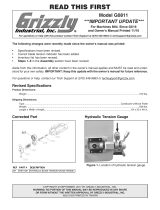
***IMPORTANT UPDATE***
For Machines Mfd. Since 08/18
and Owner's Manual Revised 02/08
37
38
36
REF PART # DESCRIPTION
36 P0668036 LOWER BLADE GUARD SET
37 P0668037 PHLP HD SCR M6-1 X 10
38 P0668038 FLAT WASHER 6MM

COPYRIGHT © MAY, 2017 BY GRIZZLY INDUSTRIAL, INC.
WARNING: NO PORTION OF THIS MANUAL MAY BE REPRODUCED IN ANY SHAPE
OR FORM WITHOUT THE WRITTEN APPROVAL OF GRIZZLY INDUSTRIAL, INC.
#MN18905 PRINTED IN TAIWAN
We recently made the following changes to the Model G0668:
• Revised electrical & control panel wiring diagram and photos.
• Revised welding station wiring diagram.
• Changed transformer manufacturer.
• Revised electrical parts.
Aside from the information contained in this update, all other content in the owner's manual applies to this
machine. For your own safety, you MUST read and understand this update and the applicable owner's
manual. Keep this update for future reference!
If you have any further questions about this manual update or the changes made to the machine, contact
our Technical Support at (570) 546-9663 or email [email protected].
READ THIS FIRST
For questions or help with this product contact Tech Support at (570) 546-9663 or techsupport@grizzly.com
Model G0668
***IMPORTANT UPDATE***
For Machines Mfd. Since June, 2008
and Owner's Manual Printed February, 2008
30V2
347V2348V2
4-1V2
4-2V2
4-3V2
4-4V2
32V2
32-1V2
Revised Electrical Parts
REF PART # DESCRIPTION
4-1V2 P0668004-1V2 POWER SWITCH W/KEY NHD CB-10 V2.06.08
4-2V2 P0668004-2V2 POWER LAMP NHD-22 V2.06.08
4-3V2 P0668004-3V2 E-STOP BUTTON NHD CB-01 V2.06.08
4-4V2 P0668004-4V2 MOTOR ON BUTTON NHD CB-10 V2.06.08
30V2 P0668030V2 TRANSFORMER YJ A174-0055 V2.01.13
32V2 P0668032V2 RELAY STON MY4S 24V 3-5A V2.01.13
32-1V2 P0668032-1V2 RELAY HOLDER STON PYF14AE V2.01.13
347V2 P0668347V2 ANNEALING PUSH BUTTON V2.06.08
348V2 P0668348V2 WELDING PUSH BUTTON V2.06.08

-2-
G0668 Update (Mfd. Since 06/08)
Revised Electrical & Control Panel
Wiring Diagram
220V
3-Phase
Power
NEMA 15-15 Plug
(As Recommended)
COLOR KEY
Black
Wt
White
Gn
Green
Rd
Red
Yel/Grn
Yg
1L/1 13NO5L/33L/2
14NO6T/34T/22T/1
A1
A2
Fuse 3A
Fuse 3A
220V
380V
415V
440V
0V
220V
0V
12V
T
Grnd
U
V
W
R1
R3 S3
12
11
10
9
8
7
6
5
NHD C120 24V
Power
Lamp
Power
Switch
Start
Button
Emergency
Stop Button
Bk
Ground
Transformer
YJ A174-0055
S
Bk Bk
Bk
13
24V
24V
A2
1
1
R
Contactor
Relay
Arita MY4S 24V 3-5A
0
S
W
Z
G
X
Ground
Hot
Hot
Hot
W
W
TS
Rd Rd
Rd Rd
T2
U
U
14
3
R2
R2
T2
V
U
2
2
11
T
T
R3
S1
R1
S3
S1
0V
12
0
0
V
V
R
R
R
Grnd
Bk
Bk
Bk
Bk
Bk
Bk
TSR
V
U
W
Bk Bk
3
3
0V
S1
R1
0V
24V
1
Wt
NHD-22 NHD CB-10
NHD CB-10
NHD CB-01
1
0
0
2
Control Panel
(see Figure 4
on Page 5)
To Motor Fan
(see Photo & Wiring
Diagram on Page 45)
To Welding Station
(see Photo & Wiring
Diagram on Page 46)
To Inverter
(see Wiring
Diagram on
Page 43)
Connect the
manufactured
leg of a power
converter
to the
"S" terminal
here.

G0668 Update (Mfd. Since 06/08)
-3-
Revised Welding Station Wiring Diagram
NO NC
ON
OFF
Annealing Button
Welding
Button
Left
Welding
Clamp
Right
Welding
Clamp
220V Transformer
Grinder
Switch
Grinder
Motor
Start Capacitor
3MFD 250VAC
1
4
6
2
3
5
Bk
Bk
Bk
Yl
Yl
Yl
COM
1 2 3 4 5 6
Gn
Bk
S1
R1
Gy
COLOR KEY
Bk
Black
Wt
White
Gn
Green
Rd
Red
Gy
Gray
Yl
Yellow
Bu
Blue
1
COM
NO NC
COM
NO NC
LIMIT
SWITCH
Yl
Figure 1. Welding station wiring.
To Electrical Panel
(see Page 2)

-4-
G0668 Update (Mfd. Since 06/08)
COLOR KEY
Bk
Black
Wt
White
Gn
Green
Rd
Red
Bu
Blue
Yl
Yellow
RM5G-2002 2 HP 220V 3-PH
Tc2
Ta2
Ta1
Tb1
Tc1
12V
Vin
GND
Iin
FM+
AM+
Y2
R
STUVW
Y1
CME
X4
X3
X2
X1
X6
C0M
X5
REV
COM
FWD
FAST
SLOW
Bk
Wt
Bk
Wt
Rd
Rd
Bk
Wt
Rd
Bk
Wt
Rd
11
12
Gn
Figure 54. Variable
speed dial wiring.
To Motor
(see Photo &
Wiring Diagram
on Page 45)
To Electrical
Panel
(see Figure
57 on Page
44, Wiring
Diagram on
Page 42)
Inverter
(see Figure 56 on Page 44)
Revised Inverter Wiring Diagram

G0668 Update (Mfd. Since 06/08)
-5-
Revised Electrical Components
Figure 2. Main electrical wiring with new
transformer.
New
Figure 3. Main electrical wiring with old
transformer.
Old

-6-
G0668 Update (Mfd. Since 06/08)
Figure 4. New control panel wiring.
New
Figure 5. Old control panel wiring.
Old
Revised Electrical Components (Cont.)
Figure 6. New annealing and welding buttons.

COPYRIGHT © JANUARY, 2015 BY GRIZZLY INDUSTRIAL, INC.
WARNING: NO PORTION OF THIS MANUAL MAY BE REPRODUCED IN ANY SHAPE
OR FORM WITHOUT THE WRITTEN APPROVAL OF GRIZZLY INDUSTRIAL, INC.
#BL17101 PRINTED IN TAIWAN
New/Revised Parts
515V2
526
518V2
520V2
REF PART # DESCRIPTION
515V2 P0668515V2 WORM GEAR W/9MM SHAFT V2.12.14
518V2 P0668518V2 HANDWHEEL W/9MM BORE V2.12.14
520V2 P0668520V2 BRACKET W/9MM BORE V2.12.14
526 P0668526 BALL BEARING 609ZZ
The following change was recently made to this machine since the owner's manual was printed:
• Redesigned guide post elevation handwheel, bracket, worm gear, and added a ball bearing.
Aside from this information, all other content in the owner's manual applies and MUST be read and under-
stood for your own safety. IMPORTANT: Keep this update with the owner's manual for future reference.
For questions or help, contact our Tech Support at (570) 546-9663 or [email protected].
READ THIS FIRST
For questions or help with this product contact Tech Support at (570) 546-9663 or techsupport@grizzly.com
Model G0668
***IMPORTANT UPDATE***
For Machines Mfd. Since 12/14
and Owner's Manual Printed 02/08
Note: If replacing older V1 parts with V2 parts,
you must replace the worm gear, bearing, brack-
et, and handwheel as a set.

COPYRIGHT © FEBRUARY, 2013 BY GRIZZLY INDUSTRIAL, INC.
WARNING: NO PORTION OF THIS MANUAL MAY BE REPRODUCED IN ANY SHAPE
OR FORM WITHOUT THE WRITTEN APPROVAL OF GRIZZLY INDUSTRIAL, INC.
#TS15611 PRINTED IN TAIWAN
Model G0668
***IMPORTANT UPDATE***
For Machines Mfg. Since February, 2013
and Owner's Manual Printed February, 2008
The following change was made to this machine since the owner's manual was printed:
• The blade shear was improved to a more heavy-duty version (see Figure 1).
This document provides an update to a portion of the owner's manual that no longer applies—aside from
this information, all other content in the owner's manual applies and MUST be read and understood for your
own safety. IMPORTANT: Keep this update with the owner's manual for future reference.
For questions or help, contact our Tech Support at (570) 546-9663 or [email protected].
Changed Parts
READ THIS FIRST
11V2
12V2
REF PART # DESCRIPTION
11V2 PB06M HEX BOLT M8-1.25 X 12
12V2 P8144Z012V2 BLADE SHEAR V2.02.13
Figure 1. Heavy-duty blade shear.
Blade
Shear

WARNING: NO PORTION OF THIS MANUAL MAY BE REPRODUCED IN ANY SHAPE
OR FORM WITHOUT THE WRITTEN APPROVAL OF GRIZZLY INDUSTRIAL, INC.
We recently made the following changes to the Model G0668:
Page 42)
Page 43
Page 46
Page 43Figure 54
Page 44Figure 56
Page 44Figure 57
Page 46Figure 59
Page 47
Keep this update for future reference!
If you have any further questions about this manual update or the changes made to the machine, contact
our Technical Support at (570) 546-9663 or email [email protected].
Model G0668
***IMPORTANT UPDATE***
Applies to Models Mfg. Since 10/11
and Owner's Manual February, 2008

220V
3-Phase
Power
NEMA 15-15 Plug
(As Recommended)
COLOR KEY
Black
Wt
White
Gn
Green
Rd
Red
Yel/Grn
Yg
1L/1 13NO5L/33L/2
14NO6T/34T/22T/1
A1
A2
Fuse 3A
Fuse 3A
220V
380V
415V
440V
0V
220V
0V
12V
24V
Grnd
T
Grnd
U
V
W
R1
R3 S3
12
11
10
9
8
7
6
5
NHD C120 24V
22 21
14 13
13 14
21 22
22 21
14 13
Power
Lamp
Power
Switch
Start
Button
Emergency
Stop Button
Bk
Ground
Transformer
1-PH 0-3VA
S
Bk Bk
Bk Bk
13
24V
24V
A2
1
1
1
1
R
Contactor
Relay
Arita MY4S 24V 3-5A
0
S
W
Z
G
X
Ground
Hot
Hot
Hot
W
W
TS
2
Rd Rd Rd Rd
T2
U
U
14
3
R2
R2
T2
V
U
2
2
11
T
T
R3
S1
R1
S3
S1
0V
12
0
0
V
V
R
R
R
Bk
Bk
Bk
Bk
Bk
Bk
TSR
V
U
W
Bk Bk
3
3
0
0
0V
S1
R1
Revised Electrical & Control Panel
Wiring Diagram
Figure 57
Page 44
Figure 55
Page 44
Page 45
Page 46
Page 43

COLOR KEY
Bk
Black
Wt
White
Gn
Green
Rd
Red
Bu
Blue
Yl
Yellow
RM5G-2002 2 HP 220V 3-PH
Tc2
Ta2
Ta1
Tb1
Tc1
12V
Vin
GND
Iin
FM+
AM+
Y2
R
STUVW
Y1
CME
X4
X3
X2
X1
X6
C0M
X5
REV
COM
FWD
FAST
SLOW
Bk
Wt
Bk
Wt
Rd
Rd
Bk
Wt
Rd
Bk
Wt
Rd
11
12
Gn
Figure 54.
Page 45
Figure
57Page
44
Page 42
Figure 56Page 44
Revised Inverter Wiring Diagram

Electrical Components
Figure 56.
Page 43
Figure 57.Page 42

1
4 2
1
4 2
NO NC
ON
OFF
Annealing Button
Welding
Button
Sensor
Left
Welding
Clamp
Right
Welding
Clamp
220V Transformer
Grinder
Switch
Grinder
Motor
Start Capacitor
3MFD 250VAC
1
4
6
2
3
5
Bk Bk
Bk
Yl
Yl
Yl
COM
1 2 3 4 5 6
Gn
Yl
Bk
S1
R1
Gy
COLOR KEY
Bk
Black
Wt
White
Gn
Green
Rd
Red
Gy
Gray
Yl
Yellow
Bu
Blue
1
Figure 59.
Welding Station Wiring Diagram
Page 42

SECTION 8: PARTS
Cabinet
KEYPAD
MPM
RPM
T.S
FUN
PROG
DATA
STOP
RUN
RESET
1
2
3
5
6
7
8
9
10
11
12
13
14
15
16
17
18
19
20
21
22
23
24
25
26
27
28
19
20
4
4-1
4-2
4-3
4-4
29
30
31
32V2
32-1V2
33
34
35
18-1
REF PART # DESCRIPTION REF PART # DESCRIPTION
1 P0668001 WHEEL DOOR LOWER 18 P0668018 WORK LAMP 220V
2 P0668002 HINGE PIN LOWER 18-1 P0668018-1 LIGHT BULB 220V
3 PS05M PHLP HD SCR M5-.8 X 8 19 P0668019 DOOR KNOB
4 P0668004 CONTROL PANEL 20 PS47M PHLP HD SCR M6-1 X 25
4-1 P0668004-1 POWER SWITCH W/KEY 21 PSB28M CAP SCREW M6-1 X 15
4-2 P0668004-2 POWER LAMP 22 PW03M FLAT WASHER 6MM
4-3 P0668004-3 EMERGENCY STOP BUTTON 23 P0668023 MOTOR ACCESS PANEL
4-4 P0668004-4 MOTOR ON BUTTON 24 PW03M FLAT WASHER 6MM
5 P0668005 BLADE CLEANING BRUSH 25 PB04M HEX BOLT M6-1 X 10
6 PS47M PHLP HD SCR M6-1 X 25 26 P0668026 CHIP PAN
7 P0668007 WHEEL DOOR UPPER 27 P0668027 DIGITAL DISPLAY
8 P0668008 HINGE PIN UPPER 28 P0668028 INVERTER RM5G 2HP 220V 3PH
9 PS05M PHLP HD SCR M5-.8 X 8 29 P0668029 CONTROL PANEL
10 P0668010 DIGITIAL DISPLAY BRACKET 30 P0668030 TRANSFORMER 1PH 0-3VA
11 PSB11M CAP SCREW M8-1.25 X 16 31 P0668031 CONTACTOR NHD C120D 220V
12 P0668012 BLADE SHEAR 32V2 P0668032V2 RELAY STON MY4S 24V 3-5A
13 P0668013 VARIABLE SPEED DIAL 32-1V2 P0668032-1V2 RELAY HOLDER STON PYF14AE
14 P0668014 AIR PUMP 33 P0668033 FUSE HOLDER
15 P0668015 BANDSAW CABINET 34 P0668034 FUSE 3A
16 P0668016 AIR HOSE 4X6MM 35 P0668035 TERMINAL BLOCK 11-POST
17 P0668017 AIR NOZZLE

MODEL G0668
20" VERTICAL METAL-CUTTING
BANDSAW
OWNER'S MANUAL
COPYRIGHT © FEBRUARY, 2008 BY GRIZZLY INDUSTRIAL, INC.
WARNING: NO PORTION OF THIS MANUAL MAY BE REPRODUCED IN ANY SHAPE
OR FORM WITHOUT THE WRITTEN APPROVAL OF GRIZZLY INDUSTRIAL, INC.
#TS10278 PRINTED IN TAIWAN


Table of Contents
SECTION 5: ACCESSORIES ......................... 31
SECTION 6: MAINTENANCE .........................
32
Schedule ...................................................... 32
Cleaning ....................................................... 32
Redressing Rubber Tires .............................
33
Lubrication ................................................... 33
SECTION 7: SERVICE ...................................
34
Troubleshooting ........................................... 34
Lower Wheel Pulley Alignment ....................
36
Tensioning V-Belts ....................................... 36
Replacing V-Belts ........................................
37
Adjusting Wheel Brush ................................
37
Wheel Alignment ..........................................
38
Aligning Table to Blade ................................
40
Blade Guides ...............................................
41
Electrical &
Control Wiring Diagram ............ 42
Inverter Wiring Diagram ...............................
43
Electrical Component
s ................................. 44
Motor Wiring Diagram ..................................
45
Welding Station Wiring Diagram ..................
46
SECTION 8:
PARTS ....................................... 47
Cabinet ......................................................... 47
Table & Lower Guide ...................................
48
Motor & Lower Wheel ..................................
49
Welding Station ............................................ 50
Guide Post ...................................................
52
Upper Wheel ................................................
53
Labels .......................................................... 54
WARRANTY AND RETURNS ........................
57
INTRODUCTION ............................................... 2
Foreword ........................................................ 2
Contact Info ...................................................
2
Machine Data Sheet ......................................
3
Identification ................................................... 5
Control Panel Identification ............................
6
SECTION 1: SAFETY .......................................
7
Safety Instructions for Machinery ..................
7
Safety Instructions for
Metal Cutting
Bandsaws ................................ 9
SECTION 2: CIRCUIT REQUIREMENTS ......
10
220V 3-Phase
Operation ............................. 10
SECTION 3: SETUP .......................................
11
Setup Safety ................................................
11
Items Needed for Setup ............................... 11
Unpacking .................................................... 11
Clean Up ......................................................
12
Site Considerations ......................................
12
Mounting to Shop Floor ...............................
13
Moving & Placing .........................................
13
Test Run ......................................................
14
Recommended Adjustments ........................
15
SECTION 4: OPERATIONS ...........................
16
Operation Safety ..........................................
16
Cutting Overview .........................................
16
Cutting Tips ..................................................
17
Workpiece Inspection ..................................
17
Basic Controls ..............................................
18
Blade Selection ............................................
19
Blade Breakage ...........................................
22
Blade Care &
Break-In ................................. 22
Chip Inspection Chart ..................................
23
Blade Changes ............................................
24
Blade Tensioning .........................................
25
Guide Post ...................................................
25
Adjusting Blade Guides & Support ..............
26
Adjusting Table Tilt ......................................
27
Blade Welding ..............................................
28

-2-
G0668 20" Vertical Metal-Cutting Bandsaw
INTRODUCTION
Foreword
We are proud to offer the Model G0668 20"
Vertical Metal-Cutting Bandsaw. This machine
is part of a growing Grizzly family of fine met
-
alworking machinery. When used according to
the guidelines set forth in this manual, you can
expect years of trouble-free, enjoyable operation
and proof of Grizzly’s commitment to customer
satisfaction.
The specifications, drawings, and photographs
illustrated in this manual represent the Model
G0668 when the manual was prepared. However,
owing to Grizzly’s policy of continuous improve
-
ment, changes may be made at any time with no
obligation on the part of Grizzly.
For your convenience, we always keep current
Grizzly manuals available on our website at
www.grizzly.com. Any updates to your machine
will be reflected in these manuals as soon as they
are complete. Visit our site often to check for the
latest updates to this manual!
If you have any comments regarding this manual,
please write to us at the address below:
Grizzly Industrial, Inc.
C
/O Technical Documentation Manager
P.O. Box 2069
Bellingham, WA 98227-2069
Email: manuals@grizzly.com
We stand behind our machines. If you have any
service questions or parts requests, please call or
write us at the location listed below.
Grizzly Industrial, Inc.
1203 Lycoming Mall Circle
Muncy, PA 17756
Phone: (570) 546-9663
Fax: (800) 438-5901
E-Mail: techsupport@grizzly.com
Web Site: http://www.grizzly.com
Contact Info

-3-
G0668 20" Vertical Metal-Cutting Bandsaw
Machine Data Sheet
data sheet
/