Duerkopp Adler 8967 Operating instructions
- Type
- Operating instructions

Contents: Page:
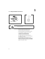
Preface and General Safety Information
Part 1: Operating Instructions Cl. 8967
1. Product Description
1.1 Short Description and Proper Use . . . . . . . . . . . . . . . . . . . . . 5
1.2 Sub-Classes . . . . . . . . . . . . . . . . . . . . . . . . . . . . . . . . . 5
1.3 Technical Specification . . . . . . . . . . . . . . . . . . . . . . . . . . . 5
2. Operating Elements and Their Function
2.1 Elements at the Sewing Head . . . . . . . . . . . . . . . . . . . . . . . . 6
2.2 Elements on the Frame . . . . . . . . . . . . . . . . . . . . . . . . . . . 8
3. Operating the Sewing Machine
3.1 Threading the Needle Thread . . . . . . . . . . . . . . . . . . . . . . . . 11
3.2 Winding the Bobbin Thread . . . . . . . . . . . . . . . . . . . . . . . . . 12
3.3 Changing the Bobbin . . . . . . . . . . . . . . . . . . . . . . . . . . . . . 13
3.4 Setting the Bobbin Thread Tension . . . . . . . . . . . . . . . . . . . . . 14
3.5 Setting the Thread Regulator . . . . . . . . . . . . . . . . . . . . . . . . 15
4. Operating the Frame
4.1 Folding Down the Table Top . . . . . . . . . . . . . . . . . . . . . . . . . 16
5. Maintenance
. . . . . . . . . . . . . . . . . . . . . . . . . . . . . . . . . 17
Contents:Page:
GB
Home


1. Product Description
1.1 Short Description and Proper Use
The special sewing machine 8967 is a single needle-double lock stitch free-arm
machine with lower transport without stroke and an upper transport with alternating
pressure feet.
The machine is designed and may only be used for sewing of textile material or leather.
1.2 Sub-Classes
8967-160180 Execution without thread trimmer,
Pressure foot lift electropneumatic.
8967-160182 Execution with electromechanical
thread trimmer for needle and
bobbin thread, electropneumatic,
automatic interlock and pressure foot lift.
1.3 Technical Specification
Needle system: System 2134-35
Max. number of stitches:
dependent on pressure foot stroke 2000, 3000 rpm
and stitch length
Maximum stitch length:
forward (F), reverse (R) 6 (F); 6 (R) mm
Pressure foot stroke: 2 - 7 mm
Maximum clearance under
the pressure feet:
When sewing: 10 mm
When raised in needle high position: 17 mm
Maximum thread thickness:
Cotton: 9/3
Synth. endless: 15/3 Nm
Core thread (poly-cotton): 20/3 Nm
Through-feed area: 281 x 135 mm
Free arm diameter 47 mm
Operating pressure: 6
+
/- 0.5 bar
Line pressure: 7 - 10 bar
Air consumption per work cycle: 0.15 NL
5

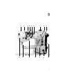
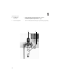
2. Operating Elements and Their Function
2.1 Elements at the Sewing Head
Element Function
1 Pressure foot screw - This screw is screwed in completely at the factory
and the position may not be changed.
2 Thread regulator - Setting the correct thread quantity for different
material thicknesses, sewing yarns and stitch lengths.
3 Control knob - Setting auxiliary tension for the needle thread.
4 Lever - Opening the main needle thread tension and
auxiliary needle thread tension.
5 Control knob - Setting the main tension for the needle thread
6 Lever - Switching the auxiliary tension on and off.
Pull the lever to the right before switching over in or-
der to free it from its catch.
7 Adjustment wheel - Setting the pressure foot stroke.
8 Lever - Bobbin thread winding device
9 Viewing glass with - Show the oil level in the reservoir.
11 fill opening The oil level must be kept above "MIN".
If necessary fill Esso "SP NK 10" up to the "MAX"
marking in the reservoir.
10 Control knob - Setting the stitch length for sewing forwards.
12 Control knob - Setting the stitch length for sewing in reverse.
13 Hand lever - Continuous adjustment of the stitch length between
the set forward and reverse stitch lengths.
14 Lever - Determining the status of the main needle thread
tension during pressure foot lift.
Lever up: Tension open.
Lever down: Tension closed.
15 Needle
Caution!
Be sure to turn off the main switch when threading or
replacing the needle.
Risk of Injury.
16 Knob - Arresting the pressure foot in the raised position.
6


2.2 Elements on the Frame
Element Function
Frame Type MG 55-3
1 Main switch - Switching the machine on and off
2 Pedal
Rest position - No function
Position forward - Sewing with desired rpm
Position "half back" - Raise pressure foot when machine at rest
Position "full back" - Thread trimming and raise pressure foot
3 Screw - Setting the Table Top Height.
Frame Type MG 56-2
4 Main switch - Switching the machine on and off
5 Pedal
Rest position - No function
Position forward - Sewing with desired rpm
Position "half back" - Raise pressure foot when machine at rest
Position "full back" - Thread trimming and raise pressure foot
6 Lever - Securing the raised table top half
7 Brace - For supporting the lowered table top in the
horizontal position.
8


3.2 Winding the Bobbin Thread
–
Place the bobbin 4 on the bobbin winder 3.
–
Pull the thread through the guide 1 and the tension 2.
–
Wind the thread approx. 5 x clockwise around the
bobbin core and tear off at the thread clamp 6.
–
Press the bobbinr lever 5 into the bobbin.
–
Sewing
The bobbin winder lever stops the procedure when
the bobbin is full.
Attention !
If the thread is not to be wound during sewing, the
pressure foot must be arrested in the raised position and
the pressure foot stroke set at the smallest value.
1
2
3
4
5
6
12

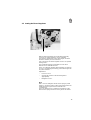
3.3 Changing the Bobbin
Caution Risk of Injury!
Turn off the main switch before changing the bobbin.
–
Bring the needle into the highest position
–
Pull the covering cap 1 from the free-arm.
–
Remove the bobbin housing 2 with bobbin 3. Hereby
raise the bobbin case flap 4 as far as possible.
–
Remove the bobbin
–
Insert a full bobbin in such a way that, when the
thread is pulled off, it turns in the direction shown in
the illustration.
–
Pull the thread through the slit 7, under the spring 6
to the hole 5.
–
Insert the bobbin case with bobbin as far as possible
into the bobbin case base and release the bobbin
case flap.
For security press in the bobbin case with your index
finger and make sure that the bobbin case flap has
caught.
–
Push on the covering cap 1.
1
2
3
4
7
6
5
13

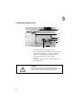
3.4 Setting the Bobbin Thread Tension
Caution Risk of Injury!
Turn off main switch.
–
Bring the needle into the highest position
–
Pull the covering cap from the free-arm
–
Remove the bobbin housing with bobbin. Hereby
raise the bobbin case flap as far as possible.
–
Carefully turn the regulating screw 1.
To the right = Increase thread tension
To the left = Decrease thread tension
The initial setting for the tension spring 2 is:
The bobbin housing must slowly lower through its
own weight. (see sketch)
–
Insert the bobbinn case with bobbin as far as
possible into the bobbin case base and release the
bobbin case flap. For security press in the bobbin
case with your index finger and make sure that the
bobbin case flap has caught.
1
2
14

3.5 Setting the Thread Regulator.
With the thread regulator the needle thread quantity
necessary for stitch formation can be regulated.
The setting is dependent on the stitch length, material
thickness and the yarn characteristics.
Only a precisely set thread regulator assures an optimal
sewing result.
The needle thread loop should glide over the hook
without excess with little tension.
In the "0" setting the greatest thread quantity is released,
such as is required by particularly great stitch length and
very thick material.
Adjustment:
–
Loosen screw 1.
–
Change the position of the thread regulator
appropriately.
–
Retighten screw 1.
Note
With a correct setting the thread check spring is pulled
approx. 1 mm down from its upper end position when the
needle thread loop passes the maximum hook
circumference.
The 1 mm dimension is a guideline. Depending on the
thread check spring tension it can be greater or smaller.
1
15

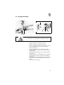
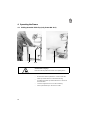
4. Operating the Frame
4.1 Folding Down the Table Top (only Frame MG 56-2)
Caution Risk of Injury!
Hold the table top with both hands when pulling down.
–
Release the table top fasteners 1 and 2 under the
table top and fastener 3 on the left frame leg.
–
Pull down the table top with both hands as shown in
the illustration.
–
Lock the diagonal brace 4 into the mounting.
–
Fold up the table top in the reverse order.
4
1/ 2
3
16

5. Maintenance
Caution Risk of Injury!
Turn off main switch.
Maintenance work must be conducted at the latest after
the number of operating hours listed in the column "
Interval". Shorter maintenance intervals may be required
when working with very linty materials.
Procedure Interval Remarks
Head
Removal of lint 8 Particularly in following areas:
accumulations Underside of the stitch bed
Transporter stays
Area around the hook
Bobbin housing top
Check the oil level in both
reservoirs 40 see subject 2.1
Element 9 and 11
Maintenance Unit
Clean insert in the 9
air filter (page 10) 500
Caution!
Interrupt the compressed air supply
and vent the system.
17
-
 1
1
-
 2
2
-
 3
3
-
 4
4
-
 5
5
-
 6
6
-
 7
7
-
 8
8
-
 9
9
-
 10
10
-
 11
11
-
 12
12
-
 13
13
-
 14
14
-
 15
15


Duerkopp Adler 8967 Operating instructions
- Type
- Operating instructions
Ask a question and I''ll find the answer in the document
Finding information in a document is now easier with AI
Related papers
-
 Duerkopp Adler 367 Owner's manual
-
 Duerkopp Adler M-TYPE 667 Operating instructions
-
Duerkopp Adler H867 Owner's manual
-
 Duerkopp Adler 382 Owner's manual
-
 Duerkopp Adler 467-180 Operating instructions
-
 Duerkopp Adler H868 Operating instructions
-
 Duerkopp Adler 567 Operating instructions
-
 Duerkopp Adler 767 CLASSIC Operating instructions
-
Duerkopp Adler 281 Operating instructions
-


Other documents
-
DURKOPP ADLER 867-M PREMIUM Owner's manual
-
Kenmore 14812181 Owner's manual
-
-
 Mauser MA 2545 User manual
-
Brother PQ-1500/1500S User manual
-
-
SINGER 20U73B User manual
-
 Consew 199RB-1A User manual
-
 Consew 199R-1A User manual
-
 Consew 103 User manual


