Page 4 <&(%$*4.8"4,7%H'*#$"&8#I%/7*,#*%4,77%JKLLLKMLNKNMJL1 Item 63621
?@<6AO
P6GQCER%ACS?
ACR%0%?ACTU
TVEA;VG?
PC;6
D@CEA6E@ET6
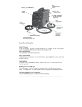
67*4$("4,7%?,2*$>
6G6TA;CT%?BVTU%4,8%UCGG1
1. A'(8%&22I%9"#4&88*4$%/&)*(I%,89%
9"#4.,(3*%*7*4$(&9*%$&%3(&'89%+*2&(*%#*$$"83%
9&)8%$&(4.0*7*4$(&9*%.&79*(%,89%+*2&(*%#*(Y"4*1
2. Q&%8&$%$&'4.%*8*(3"Z*9%*7*4$("4,7%/,($#1%%
Wear dry, insulating gloves. Do not touch electrode
holder, electrode, welding torch, or welding wire with
bare hand. Do not wear wet or damaged gloves.
3. T&88*4$%$&%3(&'89*9I%R<TCK/(&$*4$*9%
/&)*(%#'//7>%&87>1
4. Q&%8&$%'#*%8*,(%),$*(%&(%9,5/%&+=*4$#1
5. S*&/7*%)"$.%/,4*5,X*(#%#.&'79%4&8#'7$%$.*"(%
physician(s) before use. Electromagnetic fields
in close proximity to heart pacemaker could cause
pacemaker interference or pacemaker failure.
6. Q&%8&$%*[/&#*%)*79*(#%$&%(,"8%&(%)*$%4&89"$"&8#1%%%
Water entering a welder will increase
the risk of electric shock.
7. Q&%8&$%,+'#*%$.*%4&(91%%E*Y*(%'#*%$.*%4&(9%
2&(%4,((>"83I%/'77"83%&(%'8/7'33"83%$.*%)*79*(1%%
U**/%4&(9%,),>%2(&5%.*,$I%&"7I%#.,(/%*93*#%
&(%5&Y"83%/,($#1%%Damaged or entangled
cords increase the risk of electric shock.
8. Q&%8&$%'#*%&'$9&&(#1
9. C8#'7,$*%>&'(#*72%2(&5%$.*%)&(X/"*4*%,89%
3(&'891%Use nonflammable, dry insulating
material if possible, or use dry rubber mats,
dry wood or plywood, or other dry insulating
material large enough to cover your full
area of contact with the work or ground.
10. ABC?%P6GQCER%D@TBCE6%DF?A%W6%
TVEE6TA6Q%AV%SVP6;%?VF;T6%CE%
@TTV;Q@ET6%PCAB%@SSGCT@WG6%
6G6TA;CT@G%TVQ6?1
<"(*%?,2*$>
@;T%@EQ%?G@R%4,8%4,'#*%2"(*1
1. T7*,(%,),>%&(%/(&$*4$%27,55,+7*%&+=*4$#1%%%
Remove or make safe all combustible materials for a
radius of 35 feet (10 meters) around the work area.
Use a fire resistant material to cover
or block all open doorways, windows,
cracks, and other openings.
2. U**/%@WTK$>/*%2"(*%*[$"83'"#.*(%8*,(%
)&(X%,(*,%,89%X8&)%.&)%$&%'#*%"$1
3. D,"8$,"8%,%#,2*%)&(X"83%*8Y"(&85*8$1%%%
Keep the work area well lit.
Make sure there is adequate
surrounding workspace. Keep the work area free
of obstructions, grease, oil, trash, and other debris.
4. Q&%8&$%&/*(,$*%)*79*(#%"8%,$5&#/.*(*#%
4&8$,"8"83%9,83*(&'#7>%(*,4$"Y*%&(%
27,55,+7*%7"H'"9#I%3,#*#I%Y,/&(#I%&(%9'#$1%%
Provide adequate ventilation in work areas
to prevent accumulation of such substances.
Welders create sparks which may ignite flammable
substances or make reactive fumes toxic.
5. C2%)&(X"83%&8%,%5*$,7%),77I%4*"7"83I%*$41I%
/(*Y*8$%"38"$"&8%&2%4&5+'#$"+7*#%&8%$.*%
&$.*(%#"9*%+>%5&Y"83%$.*%4&5+'#$"+7*#%$&%,%
#,2*%7&4,$"&81 If relocation of combustibles is
not possible, designate someone to serve as
a fire watch, equipped with a fire extinguisher,
during the cutting process and for at least one
half hour after the cutting is completed.
6. Q&%8&$%)*79%&(%4'$%&8%5,$*(",7#%.,Y"83%
,%4&5+'#$"+7*%4&,$"83%&(%4&5+'#$"+7*%
"8$*(8,7%#$('4$'(*I%,#%"8%),77#%&(%4*"7"83#I%)"$.&'$%
,8%,//(&Y*9%5*$.&9%2&(%*7"5"8,$"83%$.*%.,Z,(91
7. Q&%8&$%9"#/&#*%&2%.&$%#7,3%"8%4&8$,"8*(#%
.&79"83%4&5+'#$"+7*%5,$*(",7#1
8. @2$*(%)*79"83I%5,X*%,%$.&(&'3.%*[,5"8,$"&8%
2&(%*Y"9*84*%&2%2"(*1%%Be aware that easily
visible smoke or flame may not be present
for some time after the fire has started.
9. Q&%8&$%,//7>%.*,$%$&%,%4&8$,"8*(%$.,$%.,#%.*79%
,8%'8X8&)8%#'+#$,84*%&(%,%4&5+'#$"+7*%
5,$*(",7%).&#*%4&8$*8$#I%).*8%.*,$*9I%
4,8%/(&9'4*%27,55,+7*%&(%*[/7&#"Y*%Y,/&(#1%%
Clean and purge containers before applying heat.
Vent closed containers, including castings,
before preheating, welding, or cutting.