Page is loading ...

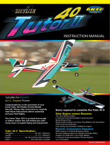
Trainer 40 Instruction Manual

Introduction
Trainer 40 Instructions
Thank you for purchasing the Trainer 40,
and welcome to the dynamic world of
model aviation! Perhaps more so than any
other branch of model Operation, model
aircraft present a unique set of challenges
Trainer 40 will help you to
master these, enabling you to
become a proficient and safe pilot.
Your Trainer 40 instruction manual
will take you step by step through
the building, installation and
Operation of every aspect
of a modern and
sophisticated
training aircraft.
Following a logical building sequence,
illustrated with both photographs
and detailed descriptions,
the Trainer 40 will
assemble with
ease and in
the minimum
of time.
To help you choose the most
suitable accessories for your model, a
complete list of recommended hardware is
included together with basic tool and
adhesive requirements.
Completed, your Trainer 40 will equip you
with the best available airframe with which
to master the challenge of model flying. It is
strongly recommended that a local club is
joined whose members can check the
model over, carry out the initial test and
trimming flights and then teach the fledgling
pilot the intricacies of model flying, all within
a safe and controlled environment.
Once solo and competent, the Student will
be able to explore the more advanced flying
capabilities of the Trainer 40, such as loops,
rolls and stall turns. These, and other
manoeuvres, are possible from the same
basic airframe and will equip the Student
with an understanding of all
things aerodynamic.

Before starting
Right hand wing panel
Left hand
wing panel
Fin
Fuselage
Remove the protective wrapping and identify the airframe components. The wing panels include the ailerons hinged and
The tailplane includes the elevator hinged and fitted. The fin includes the rudder hinged and fitted. The fuselage includes
mount and noseleg bracket fitted and the control pushrods.
Open the large accessory bag and identify the Contents.
Keep the smaller bags sealed until their parts are required
for use, this will prevent losing any item.
fitted.
the engine
A Fuel tank with accessories and
foam packing
B Nose wheel and pair of
main wheels
C Selection of spare wood for any
minor repairs
D Engine Spinner and securing
screws
E Various mounting hardware and
moulded components
F Wing retaining elastic bands
G Main undercarriage legs
H Nose wheel undercarriage leg
J Aileron pushrods
K Seif adhesive covering repair
strip
L Aileron servo mounting tray
and bearers
Further items and tools required
In order to build your Trainer 40 model a selection of hand
tools and adhesives will be required.
These include:
Steel ruler
Cyanoacrylate adhesive medium viscosity
5 minute epoxy adhesive
30 minute epoxy adhesive
Pliers
Side cutters
Modelling knife
Small file
Small allen key
Feit tip pen
Ball point pen
Masking tape
Pin chuck with 1.5mm and 2mm drills
Small cross point screwdriver

Trainer 40 Instructions
Joining the wing panels
1. Locate the wing joiner and slide it into the slot of the left hand wing panel. If required, carefully file the opening of the slot to
allow the joiner to pass freely into the wing. Using a pen, mark onto the joiner the centre line position. Trim away the covering at the
aileron servo openings on the wing underside.
1.1 Correct orientation of the wing joiner
4fc ^r
1.2 Mark the wing joiner with the wing
centre line
1.3 Trim away the covering at the aileron
servo openings
2. Following the adhesive's instructions, mix up sufficient five minute epoxy and spread the adhesive evenly onto all sides of one
half of the wing joiner. Making sure the joiner is the correct way up, push the joiner into the left hand wing panel up to the centre
line mark, wiping off any excess adhesive. Allow epoxy to set.
2.1 Applying epoxy to one half of joiner 2.2 Pushin left hand wing panel 2.3 Wiping off excess adhesive
3. Trial fit the right hand panel by sliding it over the protruding joiner, checking that the two wing panel faces meet without an
excessive gap. Note that the wing is not flat but has a slight bend, called dihedral. This is built in automatically using the joiner and
panel faces. When satisfied apply PLENTY of epoxy to the joiner and panel face, sliding the joiner into the right hand wing panel and
bringing the two wing halves together. To ensure sufficient working time use 30 min or 1 hour epoxy. Wipe off any excess adhesive
and use masking tape to hold the panels aligned together. Allow the epoxy to set and remove the tape.
3.1 Applying epoxy to the joiner
and panel face
4. Approximately six millimetres from
the wing join, apply masking tape to
each panel all around the wing. Using a
piece of card or thin wood, scrape
five minute epoxy into the join between
the two masking tape runs. Remove
the tape and allow the epoxy to set.
3.2 Pushing the right hand panel over
the joiner
3.3 Using masking tape to hold the
panels aligned together
4.1 Masking tape applied all around
wing join
4.2 Scraping epoxy into the join

Trainer 40 Instructions
:
itting the aileron servc
5. Position the aileron servo mounting tray centrally over the cut-out in the wing underside. Using a Sharp modelling knife score
around the tray being carefui only to cut through the covering and not the wing sheeting beneath. Remove the covering and glue the
tray in place using medium cyanoacrylate adhesive. Dependant upon the depth of the servo, it may be necessary to glue the two
servo spacers to the tray to raise the servo to clear the wing.
T
5.1 Aileron servo tray and servo spacers 5.2 Scoring around aileron servo tray
5.3 Tray glued to wing and spacers
glued to tray
6. Following the manufacturer's instructions, fit the rubber servo mounting grommets and brass ferrules supplied with the radio
enuipment to the aileron servo and locate the servo in the tray. Drill 1.5mm pilot holes for the four securing screws supplied with the
and screw the servo in place, orientating the servo lead to the front of the model.
6.1 Installing aileron servo 6.2 Drilling pilot holes 6.3 Screwing servo in place
7. Centre the aileron servo by switching on the radio equipment with the sticks centralised and trim levers at neutral. Switch off and
disconnect the aileron servo. Trim off the two unused arms from the servo arm. With the servo arm placed parallel with the
wingspan, push the arm onto the servo. Using a 2mm drill, open out the holes in the servo arms corresponding to approximately
11 mm each side of centre.
7.1 Trimming off the unused servo arms 7.2 Aileron servo centred with
arm attached
7.3 Drilling out the servo arm to 2mm
8. Identify the hardware used in the
aileron linkage as shown in the
photograph. Screw in place the two aileron
torque rod horns to an equal distance of
25mm from the wing underside
8.1 Aileron drive hardware
8.2 Aileron torque rod horns in place

Trainer 40 Instructions
9. Thread a plastic clevis keeper onto each of the two clevises. Holding the threaded pushrods using pliers screw the two nylon
clevises onto the ends of the pushrods. Open the clevises and snap them into the torque rod horns.
9.1 Threading clevis keeper onto a clevis
9.2 Screwing the clevises to
the pushrods
9.3 Connecting the clevises to the
torque rod horns
10. Holding in turn each aileron centred with the wing, mark the position where the pushrod crosses the 2mm hole in the servo arm
with a felt tip pen. Using a pair of pliers, bend the pushrod up through 90 degrees at this point and cut off the excess length,
leaving 6mm of pushrod after the bend.
10.1 Marking the pushrod bend position 10.2 Bending the pushrod at 90 degrees 10.3 Trimming off the excess length
11. Thread the pushrods into these holes followed by a swing keeper onto the pushrods, snapping the keepers into place
on the pushrods.
11.1 Pushrod threaded through servo
arm hole
11.2 Swing keeper threaded
onto pushrod
11.3 Swing keeper snapped %&
onto pushrod
J
12. Reconnect the servo to the receiver and check that the ailerons are centred at neutral. The clevises can be undipped from the
torque rod horns and wound in or out to achieve this. Secure the arm to the servo using the manufacturer's screw. Finally, push the
clevis keepers closer to the torque rod horns. Note that one aileron will rise and one will fall - this is correct and is
necessary to effect a turn.
12.1 Securing arm to servo
12.2 Clevis keepers in final position
12.3 Completed aileron
servo installation

Trainer 40 Instructions
Fitting the undercarriage legs and wing retaining dowels
13. Identify the undercarriage components as shown in the photograph.
These include: three wheels, six wheel retaining collets, a nose leg, nose
leg steering arm, two main undercarriage legs, two main undercarriage
clamps and four clamp retaining screws.
13.1 Undercarriage hardware
14. On the underside of fuselage, locate the slot for the main undercarriage, cutting through and removing the covering material.
Insert the two undercarriage legs into the holes in the mounting blocks and secure the legs with the two undercarriage clamps and
four retaining screws.
14.1 Cutting away the covering over the
main undercarriage slot
14.2 Inserting the main undercarriage legs
14.3 Completed main
undercarriage fixing
15. Connect the nose leg steering arm to the lower wire pushrod in the front of the fuselage and engage it into the slot of the nose
leg moulding. Pass the nose leg through the nose leg moulding and into the steering arm. Note that the groove in the leg should
face the front of the model and will engage with the screw in the steering arm. Tighten the screw of the steering arm onto
the nose leg.
-^Mrv
15.1 Nose leg steering arm located into
nose leg moulding
15.2 Fitting the nose leg to the nose
leg moulding
15.3 Tightening the steering arm screw
16. Fit a wheel collet to each of the
three undercarriage legs in a position
just outside the bend of the axles. Add
the wheels and retain them with three
further collets ensuring the wheels can
rotate freely. Securely tighten the
collet screws.
16.1 Fitting the inboard collets 16.2 Fitting the wheels and securing
with the outboard collets

Trainer 40 Instructions
17. Using a finger, locate the two wing dowel holes below the wing seating on each side of the fuselage side. Cut away and remove
the covering material at these points and insert the two wing dowels through the holes. Measure the dowels to ensure they are
protruding an equal amount and apply a small amount of medium cyanoacrylate to secure them.
17.1 Cutting away the covering
17.2 Inserting the dowels
17.3 Secure with a drop of medii
cyanoacrylate
•
itting the tail surfaces
18. Using the slot edges as a guide, cut
through and remove the covering
material from the fin and tailplane slots
at the rear of the fuselage.
18.1 Carefully cut through and remove the 18.2 Repeat for the tailplane slot
covering at the fin slot position
19. Assemble the wing centrally to the fuselage and secure it using two wing elastic bands. Trial fit the tailplane by sliding it fully in
place into the tailplane slot. Align it to the fuselage by checking the measurements shown the diagram. Using the wings as a
reference, check that it sits perpendicular to the fuselage by viewing from the rear.
c=ci
19.1 Trial fitting the tailplane
19.2 Tailplane alignment measurements
B B1
20. Using a felt tip pen, mark onto the tailplane upper and lower surfaces the fuselage shape. Remove tailplane from fuselage.
20.1 Marking the fuselage shape onto
the tailplane upper surface
20.2 ....and onto the lower surface
20.3 Marked lines on tailplane

Trainer 40 Instructions
21. Using a modelling knife and ruler carefully cut through ONLY the covering material inside of the marked lines.
Remove the covering material and clean off any trace of pen marks.
21.1 Cutting through only the
covering material
21.2 Covering removed from upper and
lower surfaces
21.3 Cleaning off any trace of pen
22. Mix sufficient 30 minute epoxy and
apply plenty to the exposed upper and
lower surfaces just formed. Slide the
tailplane back into place wiping clear any
excess adhesive, including within the fin
slg^Once more check that the tailplane is
afljwed to the fuselage and leave to cure.
22.1 One hour epoxy applied to both
sides of the tailplane
22.2 Cleaning off excess adhesive
23. Slide the fin into the slot in the rear of the fuselage above the tailplane, checking that it is standing perpendicular to the tailplane
by viewing from the rear. Using a felt tip pen, mark the shape of the fuselage onto both sides of the fin. Remove the fin and, in a
similar way to the tailplane, cut carefully through ONLY the covering material inside of the marked lines. Remove covering material.
23 1 Marking the fuselage shape onto
£ sides of the fin
23.2 Cutting through only the
covering material
23.3 Covering removed from both sides
of the fin
24. Apply plenty of 30 minute epoxy to both sides of the exposed lower part of the fin and slide it in place into the fuselage. Wipe
clear any excess adhesive, checking once more that it is aligned perpendicular to the tailplane. Leave to cure.
24.1 30 minute epoxy applied to both
sides of fin
24.2 ....and to the underside of the
fin strake
24.3 Fin in place and perpendicular

Trainer 40 Instructions
Fitting the fuel tank
25. Identify the fuel tank and its
hardware. Following the diagrams
included, assemble the fuel tank
ensuring that the clunk is free to move
from side to side and up and down. This
will ensure that fuel is delivered
to the engine regardless of the model's
attitude. Tighten the bung screw to
seal the fuel tank.
25.1 Fuel tank and clunk assembly 25.2 Sealing the fuel tank by tightening
the bung screw
26. Pass the fuel tank through the wing opening in the fuselage and into the nose of the model, the neck of the tank protruding into
the opening at the centre of the metal engine mount. Using the foam packing supplied with the fuel tank, support the tank by
packing it around the tank bay.
26.1 Pass the tank into the fuselage
Installing the engi
26.2 Fuel tank neck protruding through
engine mount former
26.3 Support the fuel tank using the
foam packing supplied
27. We recommend the MDS 40 PRO
two stroke engine for powering the
Trainer 40. This powerful, easy to handle,
quiet engine will give many hours of
trouble free, smooth running.
Identify the engine mounting hardware
consisting of two metal clamping
plates, four mounting screws, four shake
proof washers and eight nuts.
27.1 MDS 40 PRO engine used in
the prototype
27.2 Engine mounting hardware
28. Connect to each of the fuel tank outlets a 100mm length of fuel tubing. Their free ends can be taped to the top of the fuselage
to keep them temporarily out of the way. With its carburettor removed, place the engine in the engine mount. The engine's
mounting lugs should sit over the grips moulded into the mount.
28.1 Fuel tubing connected to fuel 28.2 Fuel tubing free ends temporarily 28.3 MDS 40 PRO engine in position on
tank outlets taped out of the way engine mounts

Trainer 40 Instructions
29. Add the clamping plates and screws to either side of the engine. From the underside, thread onto the screws a shake proof
washer and nut. Tighten the screws evenly so that the clamping plates are not distorted and ensure that the engine remains pointing
straight. Finally, add the remaining nuts to each of the screws and tighten in position.
29.1 Clamping plates and screws
in position
29.2 Adding the shake proof washer
and nut
29.3 Lock nuts added and tightened
30. The engine's throttle is controlled by the movement of a pushrod located in the front, upper part of the fuselage. Thread the
pushrod's Z bend into a hole in the carburettor's throttle arm and, following the engine manufacturer's instructions, secure the
carburettor to the engine. Attach also the engine's silencer, ensuring the holding screws are well tightened. Trim to length and
connect the fuel tank's clunk tank outlet to the engine^ carburettor and the fuel tank's upper vent to the silencer's pressure nipple.
T^remaining fuel tank outlet is the filling port and the tubing is simply sealed using a suitable clean screw.
30.1 Attaching the pushrod Z bend to
the throttle arm
30.2 Securing the engine's silencer
in place
30.3 Connecting the fuel tubing to
the engine
31. Looking from the rear of the model, the rudder horn is fitted on the left hand side of
the rudder at a position approximately 25mm from the base of the rudder. Hold the
horn in place on the rudder, aligning the horn clevis holes with the rudder hinge centre
lir ^pbnd drill through the horn mounting holes into the rudder with a 2mm drill. Secure
the horn in position with two 11 mm long self tapping screws which pass through the
horn, into the rudder and into the horn backing plate.
31.2 Drilling the rudder for fixing screws
31.3 Securing the horn to the rudder
using two screws and backing plate
31.1 Rudder horn position
31.4 Position horn holes in line with
control surface hinge

Trainer 40 Instructions
32. Looking from the rear of the model, the elevator horn is fitted on the right hand underside of the elevator. It should be held at a
distance of approximately 20mm from the centre of the model, with the horn clevis holes aligned with the elevator centre line. Usinc
a 2mm drill, drill the elevator for the securing screws. Secure the horn in position in a similar way to the rudder horn.
32.1 Elevator horn position 32.2 Drilling the elevator for
fixing screws
32.3 Securing the horn to the elevator
using two screws and backing plate
I
Installing the fuselage servo
33. Following the manufacturer's instructions, fit the rubber servo mounting grommets and brass ferrules supplied with the radio
equipment to the elevator, rudder and throttle servos and remove the two wooden pushrods from the fuselage. The servos are
mounted in a ply tray pre-installed in the fuselage. Observe the photograph showing the servo arrangement and install the server^
into the plywood tray. Drill 1.5mm pilot holes for the four securing screws supplied with each servo and screw the servos in placer
33.1 Arrangement of rudder, elevator
and throttle services
33.2 Install the servos, allowing their leads
to pass underneath the tray towards the
throttle servo
33.3 Drill 1,5mm pilot holes for the
securing screws and screw in place
Installing the elevator pushrod
34. Locate the slot for the elevator pushrod
(on the right hand side of the fuselage,
looking from the rear) and cut through and
remove the covering. Note that the elevator
pushrod is the longer of the two wooden
pushrods. Insert the threaded end of the
pushrod through the fuselage opening at
the wing position, down into the fuselage
and out through the slot.
34.1 Cutting through and removing the
covering material from the pushrod slot
34.2 Threaded end of pushrod passed
through slot
35. Fit a plastic clevis keeper onto a clevis and screw the clevis onto the pushrod. Open the clevis and snap it in place into the
middle hole of the elevator horn.
35.1 Fitting clevis keeper onto
a clevis
35.2 Threading clevis onto end
of pushrod
35.3 Clevis snapped into middle hole of
elevator horn

Trainer 40 Instructions
36. Centre the elevator servo by switching on the radio equipment with the sticks centralised and trim levers at neutral. Switch off
and disconnect the servo. Using a 2mm drill, open out the hole in a servo arm which corresponds approximately to 11mm from
centre. Trim off any unused sides of the arm and position it on the servo in line with the width of the fuselage.
36.1 Open out with a 2mm drill the hole
in the servo arm corresponding to 11mm
from centre
36.2 Using side cutters, cut off any
unused arms
36.3 Servo arm in place aligned with
width of fuselage
37. With the elevator held at neutral, mark
the wire where it passes over
the hole in the servo arm.
37.1 Elevator held at the neutral position
37.2 Mark the wire where it passes over
the hole in the servo arm
38. Release the clevis from the horn
and pull the pushrod clear from the
fuselage a sufficient distance to allow
a 90 degree bend to be formed at the
marked position. Cut off any excess
wire to leave 6mm of pushrod after
the bend.
38.1 90 degree bend formed at
marked position
38.2 Cut off excess wire to leave
6mm of pushrod beyond the bend
emove the arm from the elevator servo and thread it over the bend formed on the pushrod followed by a swing keeper,
sniping the keeper into place.
39.1 Servo arm threaded onto pushrod
39.2 Swing keeper in place on pushrod 39.3 Swing keeper snapped over pushrod
40. Replace the arm onto the elevator
servo, securing in place with the
radio manufacturer's screw. Re-attach
the clevis and slide the clevis keeper
closer to the horn.
40.1 Servo arm secured in place with 40.2 Clevis replaced and clevis keeper in
manufacturer's screw final position

Trainer 40 Instructions
I'-HUH
nstalling the rudder and nose leg pushr<
41. Locate the slot for the rudder pushrod (on the top face of the left hand side of the fuselage, looking from the rear) and cut
through and remove the covering. Insert the threaded end of the pushrod through the fuselage opening at the wing position, down
into the fuselage and out through the slot.
41.1 Cutting through and removing the
covering material from the pushrod slot
41.2 Locate the pushrod using a loop of
flex and pull it through the opening
41.3 Threaded end of pushrod passed
out of slot
42. Thread a plastic clevis keeper onto a clevis and screw the clevis onto the pushrod. Open the clevis and snap it in place into the
middle hole of the rudder horn.
42.1 Threading clevis keeper onto a clevis 42.2 Threading clevis onto end of pushrod 42.3 Clevis snapped into middle hole of
rudder horn
43. Centre the rudder servo by switching on the radio equipment with the sticks centralised and trim levers at neutral. Switch off ana
disconnect the servo. Using a 2mm drill, open out the hole in a servo arm which corresponds approximately to 11mm from centre.
Note that as well as operating the rudder, the rudder servo also controls the steerable nose leg, utilising the opposite side of the
servo arm to do this. Trim off any unused sides of the arm and position on the servo in line with the width of the fuselage.
43.1 Open out with a 2mm drill the hole
in the servo arm corresponding to 11mm
from centre
43.2 Using side cutters, cut off any
unused arms
43.3 Servo arm in place aligned with
width of fuselage
44. With the rudder held at neutral, mark
the wire where it passes over the
hole in the servo arm.
44.1 Rudder held at the neutral position
44.2 Mark the wire where it passes ove
the hole in the servo arm

Trainer 40 Instructions
45. Release the clevis from the horn and
pull the pushrod clear from the fuselage
a sufficient distance to allow a 90 degree
bend to be formed at the marked
position. Cut off any excess wire to
leave 6mm of pushrod after the bend.
45.1 90 degree bend formed at
marked position
45.2 Cut off excess wire to leave
6mm of pushrod beyond the bend
46. Remove the servo arm. Unscrew the grub screw from the centre of an adjustable connector and attach the connector to the
rudder servo arm approximately 11mm from the centre and on the opposite side to the rudder pushrod. Only tighten the screw into
the first nut an amount to allow the connector to freely rotate and then apply a small drop of medium cyanoacrylate and add the
second lock nut and tighten the two nuts together. Check that the connector is still free to rotate and replace the central grubscrew.
46.1 Connector illustration
46.2 Connector fitted to rudder
control horn
46.3 Small drop of medium cyanoacrylate
applied together with locknut
47. Thread the rudder servo arm over the bend formed on the rudder pushrod followed by a swing keeper, snapping the
keeper into place.
47 J Servo arm threaded onto pushrod
..#
47.2 Swing keeper in place on pushrod
47.3 Swing keeper snapped over pushrod
48. Thread the steerable nose leg
pushrod through the adjustable
connector, at the same time replacing
the arm onto the rudder servo. With the
nose wheel held centred, mark the
pushrod at a position 8mm beyond the
adjustable connector. Remove the servo
arm and cut the pushrod to the
marked line.
48.1 Nose wheel held centred 48.2 Marking nose leg pushrod position

Trainer 40 Instructions
49. Pass the pushrod again through the connector and replace the arm onto the servo, securing in place with the radio
manufacturer's screw. With the wheel held centred, tighten the grub screw of the connector onto the pushrod. Re-attach the rudder
clevis and slide the clevis keeper closer to the horn.
49.1 Nose leg pushrod through
connector and securing servo arm in
place with manufacturer's screw
49.2 Tightening connector grub screw
with wheel centred
49.3 Clevis replaced and clevis keeper
in final position
Installing the receiver switch
50. Form the switch operating arm from
one of the discarded pieces of wire
pushrod. Bend a 90 degree bend of
approximately 8mm length on one end of
the wire. Check the fit of the wire in the
hole in the switch and if necessary open
out the hole to suit.
50.1 Bending the first bend of the switch
operating wire
50.2 Open out the hole in the switch to
suit the wire
51. Place the backing plate of the switch
over the remaining rectangular hole in the
servo tray and use it to drill two, 2mm
holes for the switch mounting. Pass the
switch from the underneath into the tray
hole, add the backing plate and secure in
place with the two screws supplied.
Drill a suitable hole for the operating arm
wire in the fuselage side in line with the
switch side.
52. On the other end of the wire make a 45
degree bend, facing towards the rear of the
model, to form a grip. Pass the wire
through the fuselage side and thread the 90
degree bend into the hole in the switch.
The wire is prevented from becoming
detached by gluing a repair piece of wood
onto the tray, allowing it to rest against the
wire. Ensure the switch operates
smoothly and that it follows convention by
arranging the operating arm to push for 'on'
51.1 Using the switch backing plate to
drill the two mounting holes
51.2 Drilling fuselage side for ^
operating arm in line with switch side
52.1 45 degree bend formed on other
end of wire
52.2 Scrap piece of wood glued to tra
to prevent the operating arm becomir
detached

Trainer 40 Instructions
Installing the throttle pushr
53. Position the throttle servo to represent maximum throttle by switching on the radio equipment with the throttle stick fully
upwards and trim lever at neutral. Check too that the servo moves in the correct direction to close the throttle. Switch off and
disconnect the throttle servo. Prepare the throttle servo arm by attaching a connector, in a similar way to the nose leg arm, at a
distance approximately 16mm from centre. Trim off any unused arms. Push the throttle to fully open, thread the connector onto the
pushrod and fit the arm onto the servo at approximately 45 degree angle, facing forwards.
53.1 Throttle stick at maximum power
(Inset shows corresponding throttle position)
53.2 Throttle servo arm with connector
in place
53.3 Servo arm at 45 degrees
54. Make a mark on the pushrod wire approximately 8mm beyond the connector, remove the arm and cut the pushrod to the mark,
arm back in place onto the pushrod and in the same position on the servo and tighten the connector grub screw. Operate the
to check that when the throttle stick is in the fully down position the carburettor throttle is almost closed without stalling the
servo. If it is not possible to reduce the servo arm movement to prevent this happening using the transmitter, the connector will
have to be moved closer to the servo arms centre and the process repeated. Check also that, by moving the throttle stick trim lever
fully downward, the engines throttle becomes completely closed, which will stop the engine if desired. Finally, secure the servo arm
using the manufacturer's screw.
54.1 Marking throttle pushrod length
54.2 Throttle stick at minimum power
54.3 Throttle in closed position
Fitting the battery, receiver a
5Fia?'ug the receiver battery into the switch
harass, wrap the battery in foam for
protection and install it into the fuselage just
behind the fuel tank. Connect all the
remaining leads into the receiver, wrap also
* in foam for protection and install into the
fuselage between the fuel tank and servo
tray. The receiver aerial should be lead out of
the receiver in a direct route and the aileron
55.1 Receiver wrapped in foam
extension lead and battery charging lead left f
or
n
ro
tection
accessible in the front of the fuselage.
55.2 Receiver and battery installed in
front of fuselage
56. Prepare an aerial pull stop by drilling two 2mm holes in a piece of the repair wood and thread the aerial into it. Drill a 2mm hole in
the fuselage side close to the rear wing dowel for the aerial outlet. With the pull stop remaining on the inside of the fuselage, lead
the aerial out through this hole, leaving the minimum of aerial between the receiver and pull stop.
56.1 Aerial pull stop
56.2 Aerial threaded through pull stop
56.3 Drilling a 2mm hole for the aerial outlet

Trainer 40 Instructions
57. Cut a piece of fuel tubing to
approximately 20mm length and push a
safety pin through the centre of the tubing.
Thread the free end of the aerial down the
tubing between the pin and push the pin
into the top of the fin. Pull the aerial tight
and push the pin firmly into the tubing.
\
\
57.1 Safety pin pushed through tubing 57.2 Aerial threaded into tubing and
pinned to fin
Fitting the propeller and spinner
58. Following the engine manufacturer's
recommendations, choose a propeller
suitable for both the engine and model
(typically a 10X6 with a 40 size two
stroke engine). Check the balance of the
propeller and if necessary lightly sand
the heavy blade to achieve a balance.
58.1 Checking propeller balance
58.2 Backplate location pegs
Push the spinner backplate onto the engine shaft followed by the propeller, washer and nut. As the compression resistance is felt, it
will feel more natural to flick the propeller with the blade tightened in the 12 o'clock position. Before tightening the nut check that
the two pegs of the backplate are resting against trailing edge of the propeller blade. Tighten the nut securely.
59. Fit the spinner using the two screws
provided. Depending on the make of
propeller, it may be necessary to trim
the cut outs in the spinner to allow
the spinner to locate into the backplate.
Tighten the screws securely and check
that the assembly rotates true.
59.1 Trimming cut outs in spinner
59.2 Tightening spinner securing screws
Trainer 40 flying instructions
Pre Flight
Before flying your Trainer 40, three essential checks need to be
carried out. These are best done, and corrected if necessary,
before arriving at the flying site. Your local club instructor should
also be asked to carry out these checks and would find it helpful
to have this manual at hand for reference to certain dimensions.
Check No. 1 - Balance point
In order for the model to fly in a controlled fashion the model
must balance with the fuselage horizontal at a point 85mm back
from the leading edge of the wing. The receiver battery can be
moved forwards or rearwards to achieve this.
Check No. 2 - Control surface movements
The amount of control surface movement also has an effect on
the control ability of the model. With the transmitter sticks at full
defection the corresponding control surface movements should
be adjusted to the dimensions below, all measured at the trailing
edge of the control surface.
Ailerons 6 mm up, 6 mm down
Elevator 12 mm up, 12 mm down
Rudder 25 mm left, 25 mm right
Equally important to check is the direction of control surface
movements. Standing behind the model, move the transmitter
sticks and observe the surface movements. Use the transmitter
servo reversing facility to correct the movement direction.
Ailerons Stick right - LH aileron down, RH aileron up
Stick left - LH aileron up, RH aileron down
Elevators Stick back - elevator up
Stick forward - elevator down
Rudder Stick right - rudder right, nose wheel moves right
Stick left - rudder left, nose wheel moves left
Check No. 3 - Engine
If the engine is brand new, follow the engine manufacturer's
starting instructions and run the engine for a couple of tanks of
fuel to ensure it will deliver adequate power with reliable
throttling. Always be aware of the dangers to yourself and other
persons from therotating propeller. Remain clear of the front of
the propeller arc once the engine is started and never point the
model towards other people, animals or property.
Flying
Before flying your model for the first time you MUST check the
control range of your radio control system. Start the engine and

Trainer 40 Instructions
have a helper hold the model ensuring that they are clear of the
propeller. Retract the transmitter aerial and walk away moving
the control sticks on the transmitter. Run the motor to full
power and repeat the movements. You should be able to walk
between 25-30 metres without interference or losing control. If
you lose control or the radio appears to have interference do not
attempt to fly. Rectify the problem and repeat the above
procedure until a satisfactory result is accomplished.
Contact the British Model Flying Association on 01162 440 028
for details of your local model flying club.
Choose a calm, bright day to test fly your Trainer 40. It is highly
recommended that your club instructor conducts the test flight
and trims out the model for you, but if this is not possible, and
the flying site rules allow beginners to fly unsupervised, follow
the instructions below.
On smooth ground, place the model pointing into wind. Hold the
model whilst you run the engine to maximum power and make
a final check that all the controls operate correctly.
^ elevator at neutral and when ready open the throttle
smoothly and positively and the Trainer 40 will accelerate. A
small amount of right rudder will be needed to hold the model
straight during the take off. As the model's speed increases the
model will become light. At this point gently apply up elevator to
lift the Trainer 40 off the ground. Hold the elevator movement
and continue climbing, keeping the wings level with small inputs
of aileron. The rudder can be returned to neutral for the
remainder of the flight.
Once a comfortable height has been reached, enter a turn
direction that will take the model away from any spectators. Use
only small aileron and elevator inputs. Fly away from yourself for
a short distance and turn again, this time onto a downwind
heading. The model should be climbing steadily throughout with
ample airspeed. Continue to fly downwind and then make
another turn to fly crosswind back towards yourself. Make one
more turn to align the model back into wind and pointing
towards the take off area. Reduce the throttle to a cruise,
maintaining sufficient power to hold the model's height and
airspeed. It is likely that with the elevator returned to neutral the
Tl^pll may want to sink or climb and this should be corrected
using the elevator trim control. Like wise, the wings may want
to bank left or right with neutral aileron. Again, this can be
trimmed out using the aileron trim.
With the trimming having taken place during the model's into
wind flight you can now enter another turn, again in a direction
away from any spectators, and fly another circuit, adjusting the
engine's throttle to maintain a constant height. This is the
correct way to control the models altitude, NOT by pulling or
pushing with the elevator control.
Remember that airspeed = safety! Flying too slowly, the model
may stall (lose lift) and crash.
It is good practice to fly both left hand and right hand turns so
large, smooth figure of eight turns should be attempted. Do not
allow the model to fly an uncomfortable distance away from you
or to drift in a direction towards spectators. Practice climbing
and descending using the engine throttle as a control but always
leaving plenty of height for recovery, should it be necessary.
As you perhaps are now aware, model flying requires a three
dimensional skill - but is very rewarding once accomplished!
To leave ample fuel for a misjudged approach, after seven or
eight minutes of flying enter a landing circuit. Do this by
reducing the throttle and descending downwind parallel with the
take off area at a comfortable distance out. Turn the model
crosswind towards you descending gradually, and turn once
more into a position directly into wind and heading towards the
landing area. Carefully adjust the throttle aiming to descend the
model onto the landing strip, keeping the wings horizontal with
small aileron inputs. As the model crosses over the strip, reduce
the .throttle to idle and allow the model to glide onto the
approach. Near to the ground gently apply a small amount of up
elevator to raise the model's nose, slowing the model and flaring
out. Judged correctly, the main wheels should touch the ground
just as the model's wing lift can no longer support the
aircraft, the model landing at the slowest possible airspeed.
Allow the model to come to rest, stop the engine using the
throttle trim, switch off the receiver and transmitter, and then
take a well-earned rest!
With more flying, confidence will grow and the Trainer 40's
flight envelope can be fully explored. Slow flying, stalling and
recovery, loops, rolls, stall turns, inverted flight and more are all
possible BUT only to be attempted for the first time with plenty
of height as insurance.
To cater for a natural progression within the sphere of model
flying, Ripmax supply a wide range of flying model aircraft from
gliders to large scale models, incorporating both kit and almost
ready to fly models. Check these out at your local model shop.
Congratulations, Happy and Safe Flying!

Ripmax Pic, Ripmax Corner,
Green Street,
Enfield EN3 7SJ
Email: [email protected]m
Tel: 020 8282 7500
Fax: 020 8282 7501
Website: www.ripmax.com
/