Page is loading ...

Danfoss scroll compressors
SM SY SZ
R22 - R407C - R134a - R404A - R507A - R513A - 50 - 60 Hz
Application guidelines
http://danfoss.us.com/


Application guidelines
3AB237986441643en-US0601
Content
Compressor model designation ..............4
Nomenclature ............................................................ 4
Danfoss scroll compression principle .....5
Features ..................................................... 6
Technical specications ...........................7
50 Hz data ................................................................... 7
60 Hz data ................................................................... 8
Dimensions ...............................................9
SM/SZ 084-090-100-110-120 ............................... 9
SM 112-124-SM/SZ147* ....................................... 10
SM/SZ147 code 3 ....................................................10
SM/SZ 148-161 ........................................................11
SM/SZ 175-185 & SY185 ....................................... 12
R and C version ........................................................12
SM/SZ 185 P, X, Y version .....................................13
SY 240-300-380 .......................................................14
Connection details ................................................. 15
Electrical data, connections and wiring 16
Motor voltage ..........................................................16
Wiring connections ...............................................16
IP rating ...................................................................... 17
Terminal box temperature ..................................17
Three phase electrical characteristics ............. 18
Danfoss MCI soft-start controller ...................... 20
General wiring information ................................21
Motor protection .................................................... 23
Voltage unbalance ................................................. 25
Approval and certications ...................26
Approvals and certicates...................................26
Pressure equipment directive 2014/68/EU ...26
Low voltage directive ...........................................26
Machines directives ............................................... 26
Internal free volume .............................................. 26
Operating conditions .............................27
Refrigerant and lubricants ..................................27
Motor supply ............................................................28
Compressor ambient temperature ..................28
Application envelope at dew temperatures . 28
Application envelopes at
mean temperatures ............................................... 31
Discharge temperature protection ................. 33
Maximum Operating Pressure (MOP)
protection .................................................................33
High and low pressure protection ...................33
Cycle rate limit ......................................................... 34
System design recommendations .........35
General ....................................................................... 35
Essential piping design considerations .......... 35
Refrigerant charge limit .......................................36
O-cycle migration ................................................ 36
Liquid ood back .................................................... 38
Specic application recommendations 39
Low ambient application ....................................39
Low load operations..............................................40
Brazed plate heat exchangers ...........................40
Electronic expansion valve .................................40
Reversible heat pump systems..........................40
Water utilizing systems ........................................42
Sound and vibration management .......43
Starting sound level ..............................................43
Running sound level .............................................43
Stopping sound level ............................................ 43
Sound generation in a refrigeration or air
conditioning system .............................................43
Installation ..............................................45
Compressor handling and storage ..................45
Compressor mounting .........................................45
Compressor holding charge ...............................46
System cleanliness .................................................46
Tubing ........................................................................46
Brazing and soldering ...........................................46
System pressure test .............................................48
Leak detection ......................................................... 48
Vacuum evacuation and moisture removal ..48
Filter driers ................................................................ 49
Refrigerant charging .............................................49
Insulation resistance and dielectric strength 49
Commissioning .......................................................50
Oil level checking and top-up ...........................50
Ordering information & packaging.......51
Packaging ................................................................. 51
Ordering information............................................51
Accessories ..............................................56

Application guidelines
4 AB237986441643en-US0601
Compressor model designation
Danfoss scroll compressors are available
both as single compressors and as tandem
units. The example below presents the single
compressor nomenclature which equals the
technical reference as shown on the compressor
nameplate.
Code numbers for ordering list are section
“Ordering information & packaging”.
For tandem and trio assemblies, please refer
to the Danfoss Parallel Application Guidelines
documentation FRCC.PC.005.
Nomenclature
Family, lubricant
& refrigerant
Nominal capacity
in thousand Btu/h at 60 Hz, R22,
ARI conditions
Nominal capacity
Family, lubricant
& refrigerant
SM: Scroll, Mineral oil, R22/R417A*
SY: Scroll, POE lubricant, R22/R417A
(R407C for SY185 to 380,
R134a, R513A for SY 240 to 380**)
SZ: Scroll, POE lubricant, R407C - R134a
(and R404A, R507A for SZ084 to SZ185)
Voltage Version Evolution
index
C
A
4
7
SZ
SY
-
A
R
CA
185
300
Single compressors
Single compressors
: brazed
Internal overload protector
A
S 112-124-147
110-240V
24 V AC
110-240V
C
: brazed
Motor protection type
V : brazed
S 084-090-100-110-120-148-161
Applies to
R : rotolock
X
P : brazed
: brazed
CB
CA
Y : rotolock
C: brazed
PA
B:
110-240V
A: 24V AC
PB
P: rotolock A: 24V AC
CB
B:
110-240V
CA C: brazed A: 24V AC
B:
110-240 V
Module voltageConnection
Internal thermostat
S 240 - 300
S 380
Electronic protection
module
S 185
Motor voltage code
3: 200-230V/3~/60 Hz
4: 380-400V/3~/50 - 460V/3~/60 Hz
SY380: 380-415V/3~/50 Hz - 460V/3~/60 Hz
6: 230V/3~/50 Hz
7: 500V/3~/50 Hz - 575V/3~/60 Hz
9: 380V/3~/60 Hz
SY380: 380-400V/3~/60 Hz
* When SM compressors are used with R417A, the factory charged mineral oil 160P must be replaced by polyolester oil 160SZ
**Only SY240 to SY380 motor voltage 4 are qualified with R513A

Application guidelines
5AB237986441643en-US0601
Danfoss scroll compression principle
In a Danfoss SM / SY / SZ scroll compressor, the
compression is performed by two scroll elements
located in the upper part of the compressor.
Suction gas enters the compressor at the suction
connection. As all of the gas ows around and
through the electrical motor, thus ensuring
complete motor cooling in all applications, oil
droplets separate and fall into the oil sump.
After exiting the electrical motor, the gas enters
the scroll elements where compression takes
place. Ultimately, the discharge gas leaves the
compressor at the discharge connection.
The gure below illustrates the entire
compression process. The centre of the orbiting
scroll (in grey) traces a circular path around
the centre of the xed scroll (in black). This
movement creates symmetrical compression
pockets between the two scroll elements.
Low-pressure suction gas is trapped within
each crescent-shaped pocket as it gets formed;
continuous motion of the orbiting scroll serves
to seal the pocket, which decreases in volume
as the pocket moves towards the centre of the
scroll set increasing the gas pressure. Maximum
compression is achieved once a pocket reaches
the centre where the discharge port is located;
this stage occurs after three complete orbits.
Compression is a continuous process: the
scroll movement is suction, compression and
discharge all at the same time.
SM SY SZ 084-090-100-110-120-148-161-175-185-240-300-380
First orbit:
SUCTION
Second orbit:
COMPRESSION
Third orbit:
DISCHARGE

Application guidelines
6 AB237986441643en-US0601
Features
In addition to the existing SM range compressors
previously available, Danfoss is completing its
range with 3 compressors.
The new SM112-124-147 and SZ147 compressors
benet from a further improved design to
achieve the highest eciency.
Gas circulation, motor cooling and oil behaviour
are improved by a new patented motor cap
design.
Part protection and assembly reduces internal
leaks and increases life durability.
Improved part isolation reduces greatly acoustic
levels.
Gas intake design induces higher resistance to
liquid slugging.
Heat shield that lowers the heat transfer between
discharge and suction gas and the acoustic level
Improved lower bearing centering
Patented motor centering spacer
Patented motor cap
New PTFE spring seal for even lower leaks
SM112-124-147 and SZ147
R22 optimized scroll prole

Application guidelines
7AB237986441643en-US0601
Technical specifications
50 Hz data
Subject to modication without prior notication
For full data details and capacity tables refer to Online Datasheet Generator : www.danfoss.com/odsg
Rating conditions
Model
Nominal
Cap. 60 Hz
Nominal cooling capacity Power input COP E.E.R.
Swept
volume
Displace-
ment
Oil
charge
Net
weight
TR W Btu/h kW W/W Btu/h /W cu.in/rev cu.ft/h oz lbs
R22 SINGLE
SM084 7 20400 69600 6.12 3.33 11.4 6.99 703 112.08 141
SM090 7.5 21800 74400 6.54 3.33 11.4 7.35 741 112.08 143
SM100 8 23100 78800 6.96 3.33 11.4 7.76 782 112.08 143
SM110 9 25900 88400 7.82 3.32 11.3 8.80 886 112.08 161
SM112 9.5 27600 94200 7.92 3.49 11.9 9.25 931 112.08 141
SM120 10 30100 102700 8.96 3.36 11.5 10.17 1024 112.08 161
SM124 10 31200 106500 8.75 3.56 12.2 10.34 1042 112.08 141
SM147 12 36000 122900 10.08 3.57 12.2 11.81 1190 112.08 148
SM148 12 36100 123200 10.8 3.34 11.4 12.14 1222 122.26 194
SM161 13 39000 133100 11.59 3.37 11.5 13.22 1331 122.26 194
SM175 14 42000 143300 12.47 3.37 11.5 14.22 1432 210.57 220
SM/SY185 15 45500 155300 13.62 3.34 11.4 15.25 1535 210.57 220
SY240 20 61200 208900 18.2 3.36 11.5 21.22 2137 271.70 331
SY300 25 78200 266900 22.83 3.43 11.7 26.70 2687 271.70 346
SY380 30 94500 322500 27.33 3.46 11.8 32.42 3263 285.28 348
R407C SINGLE
SZ084 7 19300 65900 6.13 3.15 10.8 6.99 703 112.08 141
SZ090 7.5 20400 69600 6.45 3.16 10.8 7.35 741 112.08 143
SZ100 8 21600 73700 6.84 3.15 10.8 7.76 782 112.08 143
SZ110 9 24600 84000 7.76 3.17 10.8 8.80 886 112.08 161
SZ120 10 28600 97600 8.99 3.17 10.8 10.17 1024 112.08 161
SZ147 12 34900 119100 9.92 3.52 12.0 11.81 1190 112.08 148
SZ148 12 35100 119800 10.99 3.19 10.9 12.14 1222 122.26 194
SZ161 13 37900 129700 11.84 3.21 11.0 13.22 1331 122.26 194
SZ175 14 40100 136900 12.67 3.17 10.8 14.22 1432 210.57 220
SZ185 15 43100 147100 13.62 3.16 10.8 15.25 1535 210.57 220
SY240 20 59100 201700 18.55 3.19 10.9 21.22 2137 271.70 331
SY300 25 72800 248100 22.73 3.2 10.9 26.70 2687 271.70 346
SY380 30 89600 305800 27.59 3.25 11.1 32.42 3263 285.28 348
R513A
SINGLE
SY240 20 37450 127783 12.1 3.10 10.59 347.8 60.5 8.00 150
SY300 25 47497 162065 14.7 3.22 10.99 437.5 76.1 8.00 157
SY380 30 58537 199734 18.1 3.23 11.03 531.2 92.4 8.40 158
TR = Ton of Refrigeration COP = Coecient Of Performance EER = Energy Eciency Ratio
Displacement at nominal speed: 2900 rpm at 50 Hz, 3500 rpm at 60Hz Net weight with oil charge
SM/SY compressors SZ compressors
Refrigerant R22 R513A R407C
Frequency 50Hz 50 Hz 50 Hz
Standard rating conditions ARI EN12900 -
Evaporating temperature 45 °F 41 °F 45°F (dew point)
Condensing temperature 130 °F 122 °F 130°F (dew point)
Sub-cooling 15 °F 18 °F 15°F
Superheat 20 °F 0 °F 20°F
For regular updates and detailed capacities, please refer to Coolselector®2 www.coolselector.danfoss.com

Application guidelines
8 AB237986441643en-US0601
Technical specications
60 Hz data
Subject to modication without prior notication
For full data details and capacity tables refer to Online Datasheet Generator : www.danfoss.com/odsg
Rating conditions
SM/SY compressors SZ compressors
Refrigerant R22/R513A R407C
Frequency 60 Hz 60 Hz
Standard rating conditions ARI standard conditions -
Evaporating temperature 45°F 45°F (dew point)
Condensing temperature 130°F 130°F (dew point)
Sub-cooling 15°F 15°F
Superheat 20°F 20°F
Model
Nominal
Cap. 60 Hz
Nominal cooling capacity Power input COP E.E.R.
Swept
volume
Displace-
ment
Oil
charge
Net
weight
TR W Btu/h kW W/W Btu/h /W cu.in/rev cu.ft/h oz lbs
R22 SINGLE
SM084 7 24600 84000 7.4 3.34 11.4 6.99 849 110 141
SM090 7.5 26400 90100 7.8 3.37 11.5 7.35 894 110 143
SM100 8 27500 93900 8.1 3.38 11.5 7.76 943 110 143
SM110 9 31600 107800 9.3 3.38 11.5 8.80 1069 110 161
SM112 9.5 34000 116000 9.6 3.53 12.1 9.25 1124 112 141
SM120 10 36700 125300 10.8 3.4 11.6 10.17 1236 110 161
SM124 10.5 37700 128700 10.6 3.56 12.2 10.34 1257 112 142
SM147 12 43600 148800 12.2 3.58 12.2 11.81 1435 112 148
SM148 12 43800 149500 13 3.37 11.5 12.14 1476 122 194
SM161 13 47600 162500 14.1 3.39 11.6 13.22 1606 122 194
SM175 14 51100 174400 15.3 3.34 11.4 14.22 1728 210 220
SM/SY185 15 55300 188700 16.3 3.39 11.6 15.25 1853 210 220
SY240 20 74100 252900 22.1 3.35 11.4 21.22 2579 272 331
SY300 25 94500 322500 27.5 3.43 11.7 26.70 3245 272 346
SY380 30 115300 393500 33.4 3.46 11.8 32.42 3939 285 348
R407C SINGLE
SZ084 7 22500 76800 7.1 3.19 10.9 6.99 849 110 141
SZ090 7.5 24400 83300 7.6 3.2 10.9 7.35 894 110 143
SZ100 8 26500 90400 8.2 3.24 11.1 7.76 943 110 143
SZ110 9 30100 102700 9.3 3.24 11.1 8.80 1069 110 161
SZ120 10 34800 118800 10.7 3.24 11.1 10.17 1236 110 161
SZ147 12 42300 144300 12.03 3.52 12.0 11.81 1435 112 148
SZ148 12 42600 145400 13.3 3.19 10.9 12.14 1476 122 194
SZ161 13 46000 157000 14.3 3.21 11.0 13.22 1606 122 194
SZ175 14 48700 166200 15.3 3.19 10.9 14.22 1728 210 220
SZ185 15 51800 176800 16.4 3.15 10.8 15.25 1853 210 220
SY240 20 71100 242700 22.7 3.14 10.7 21.22 2579 272 331
SY300 25 87900 300000 27.5 3.2 10.9 26.70 3245 272 346
SY380 30 107300 366200 33.5 3.2 10.9 32.42 3939 285 348
R513A
SINGLE
SY240 20
51208 174727 15.9 3.22 10.99 347.8 73 8.00 150
SY300 25
64441 219879 19.5 3.30 11.25 437.5 91.9 8.00 157
SY380 30
69586 79439 24.7 3.22 10.99 531.2 111.6 8.40 158
TR = Ton of Refrigeration COP = Coecient Of Performance EER = Energy Eciency Ratio
Displacement at nominal speed: 2900 rpm at 50 Hz, 3500 rpm at 60Hz Net weight with oil charge
For regular updates and detailed capacities, please refer to Coolselector®2 www.coolselector.danfoss.com

Application guidelines
9AB237986441643en-US0601
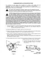
Dimensions
SM/SZ 084-090-100-110-120
All dimensions in inch
Grommet
Ø 9.45
Ø 9.06
Ø 10
A: 18.29
B: 20.26
A: 15.02
B: 16.99
4.54
A: 11.60
B: 13.02
3.95
A: 20
B: 21.97
A: 9.92
B: 11.35
A: 5.59
B: 7.02
3.91
11.18
11.18
8.66
8.66
A: 6.42
B: 7.05
7.29
A: 6.17
B: 6.38
A: SM/SZ 084-090-100
B: SM/SZ 110-120
45°
30°
6.41
3.89
4 holes Ø 0.76
HM 8 bolt
Lock washer
Flat washer
Steel mounting sleeve
Rubber grommet
Nut
1.10 inch
Compressor
base plate

Application guidelines
10 AB237986441643en-US0601
Dimensions
SM 112-124-SM/SZ147*
* except code 3
SM/SZ147 code 3
All dimensions in inch
Grommet
30 °
7.5
Ø 8.69
A: 21.06
B: 21.26
4.61
7.44
Ø 8.80
A: 10.84
B: 20.04
A: SM112
B: SM124-147
3.98
Ø 9.57
10.94
4 holes
Ø 0.75
60 °
7.09
6.06
9.06
7.5
6.81
30 °
9.06
Ø 8.82
Ø 9.57
4 holes
Ø 0.75
6.18
6.06
9.06
7.5
7.87
6.06
6.81
9.06
7.5
30°
30°
60°
3.98
20.04
21.26
10.94
HM 8 bolt
Lock washer
Flat washer
Steel mounting sleeve
Rubber grommet
Nut
1.10 inch
Compressor
base plate

Application guidelines
11AB237986441643en-US0601
Dimensions
SM/SZ 148-161
Grommet
All dimensions in inch
Ø 10.47
7.32
7.79
17.33
7.87
3.92
6.24
4 holes
Ø 0.76
6.8
8.66
8.66
11.18
14.08
8.23
11.18
SM 148-161 code 3 SM 148-161 code 4
30°
23.27
7.09
14.79
4.54
10.65
Ø10.47
3.92
17.33
7.36
13.03
3.89
HM 8 bolt
Lock washer
Flat washer
Steel mounting sleeve
Rubber grommet
Nut
1.10 inch
Compressor
base plate

Application guidelines
12 AB237986441643en-US0601
Dimensions
SM/SZ 175-185 & SY185
R and C version
Grommet
All dimensions in inch
7.95
6.57
26.69
25.24
7.79
20.8
9.33
7.08
4.33
Ø 10.07
Ø 10.47
Brazed version Rotolock version
Ø 12.45
7.67
6.73
13.59
4 holes
Ø 0.76
11
14.59
12
7.75
7.08
16.92
9.38
7.36
7.32
30°
HM 8 bolt
Lock washer
Flat washer
Steel mounting sleeve
Rubber grommet
Nut
1.10 inch
Compressor
base plate

Application guidelines
13AB237986441643en-US0601
Dimensions
SM/SZ 185 P, X, Y version
Grommet
All dimensions in inch
HM 8 bolt
Lock washer
Flat washer
Steel mounting sleeve
Rubber grommet
Nut
1.10 inch
Compressor
base plate
Brazed version Rotolock version
Ø 10.07
Ø 10.47
24.21
6.02
SANS COMPRESSION: 1.16
/ Without compression
AVEC COMPRESSION: 1.10
/ With compression
3.07
25.59
Ø 12.48
3.18
13.59
7.24
16.85
7.0
7.55
12
14.6
6.14
11
7.36
3.26
8.46
7.36
20.80±0.04
90°
35°
30°
90°
4 holes
Ø 0.76
Ø 10.47
Ø 10.07
25.55
24.17
7.36
8.46
153
77
Ø 12.48
13.59
7.67
16.85
6.73
11
7.28
7.55
12
14.06
7.0
3.18
3.26
6.02
20.80±0.04
SANS COMPRESSION: 1.16
/ Without compression
AVEC COMPRESSION: 1.10
/ With compression
4 holes
Ø 0.76
90°
35°
30°
90°

Application guidelines
14 AB237986441643en-US0601
Dimensions
SY 240-300-380
All dimensions in inch
Grommet
Lock washer *
HM 10 Bolt *
Large at *
1.06 inch washer
Steel mounting sleeve
Rubber grommet
Nut *
1.41 inch
Compressor base plate
* not supplied with compressor
7.36
35°
4 holes Ø0.98
15.43
15.43
12
7.95
8.11
7.32
17.87
11.58
7.62
30°
A: SY/SZ240
B: SY/SZ300
C: SY/SZ380
8.23
A&B: 15.83 - C: 16.54
5.5
Ø13.54
Discharge
A&B: 1”1/8
C: 1”3/8
Ø13.11
A: 27.2±2
B: 67.63±2
C: 28.58
A: 24.33
B: 24.76
C: 25.71
A: 18.88±1.2
B: 19.31±1.2
C: 20.26±1.2
Suction
A&B: 1”5/8
C: 2”1/8
8.50
7.7
3.43
3.86
6.29
90°
187
Discharge 1”1/8
Suction
A: 1”1/2
B: 1”5/8
15.91
A: SY/SZ240
B: SY/SZ300
15.90
8.19
90°
30°
35°
4 holes Ø0.98
15.43
15.43
12
7.95
7.32
17.87
11.58
7.62
8.23
5.5
Ø13.54
Ø13.11
A: 27.2±2
B: 67.63±2
A: 24.33
B: 24.76
A: 18.88±1.2
B: 19.31±1.2
8.50
7.7
3.43
3.86
6.29
Brazed version Rotolock version

Application guidelines
15AB237986441643en-US0601
Dimensions
Connection details
Suction and discharge
connections
Oil drain connection
Oil equalisation connection
Oil sight glass
Schrader
The oil drain connection allows oil to be removed
from the sump for changing, testing, etc. The
tting contains an extension tube into the oil
sump to more eectively remove the oil. The
connection is a female 1/4" are tting.
Note: on SY240 to 380, it is not possible to drain
oil from the suction connection.
SM/SZ 112-124-147: 1"3/4 rotolock connector
allowing use of 1"3/4-7/8" or 1"3/4-1"1/8
SY 240-300-380: 1/2" are
Other models: 3/8" are
This connection must be used to mount an oil
equalisation line when two or more compressors
are mounted in parallel (please refer to
Danfoss Parallel Application Guide lines reference
FRCC.PC.005 for details).
The oil ll connection and gauge port is a 1/4"
male are connector incorporating a schrader
valve.
All Danfoss SM / SY / SZ scroll compressors come
equipped with a sight glass (1"1/8-18 UNEF)
which may be used to determine the amount and
condition of the oil contained within the sump.
Model
SM/SZ084-090-100-110-
120-148-161
SM/SZ 175 - SM/SZ/SY185
SM 112-124 -
SM/SZ 147
SY 240 - 300 SY 380
Version V R-Y C-P-X AL MA - MB AA - AB AA - AB
Suction and discharge connection brazed rotolock brazed brazed rotolock brazed brazed
Oil sight glass threaded threaded threaded threaded threaded threaded threaded
Oil equalisation connection 3/8" are 3/8" are 3/8" are rotolock 1"3/4 1/2" are 1/2" are 1/2" are
Oil drain connection - 1/4" are 1/4" are - 1/4" are 1/4" are 1/4" are
Low pressure gauge port (schrader) 1/4" are 1/4" are 1/4" are 1/4" are 1/4" are 1/4" are 1/4" are
Brazed version Rotolock version
Brazed Rotolock Sleeve included
SM/SZ 084-090-100
Suction 1" 1/8 - -
Discharge 3/4" - -
SM/SZ 110-112-120-
124-147-SM148&161
Suction 1" 3/8 - -
Discharge 7/8" - -
SM/SZ 175-185
Suction 1" 5/8 2" 1/4 1" 3/8
Discharge 1" 1/8 1" 3/4 7/8"
SY 240-300
Suction 1" 5/8 2" 1/4 1" 5/8
Discharge 1" 1/8 1" 3/4 1" 1/8
SY 380
Suction 2" 1/8 - -
Discharge 1" 3/8 - -
1
2
2
1

Application guidelines
16 AB237986441643en-US0601
Electrical data, connections and wiring
The terminal box is provided with a Ø 1" and a
Ø 1.14" knockouts.
Motor voltage
Wiring connections
Danfoss SM / SY / SZ scroll compressors are available in ve dierent motor voltages.
Electrical power is connected to the compressor terminals by Ø 3/16" (4.8 mm) screws. The maximum
tightening torque is 2.2ft.lb. Use a 1/4" ring terminal on the power leads.
The terminal box is provided with 2 double
knockouts for the power supply and 3 knockouts
for the safety control circuit.
The 2 power supply, double knockouts
accommodate the following diameters:
Ø 1"3/4 hole (for a 1"1/4 conduit) and Ø 1"3/8
hole (for a 1" conduit),
Ø 1.26" hole & Ø 1" hole
The 3 other knockouts are as follows:
Ø 0.81"
Ø 7/8" (for a 1/2" conduit)
Ø 0.65"
SM / SZ 084 - 090 - 100 - 110
- 112 - 120 - 124 - 147* -148*
- 161*
*Except for motor voltage
code 3
SM / SZ 148 & 161 code 3-175-
185 & SY185 - R & C version
The terminal box is provided with a Ø 1.59" hole
for power supply and a Ø 0.65" knockout.
SM/SZ 147 code 3
Terminal box
Ø 1 inch knockout
Power supply
Ø 1.14 inch knockout
Ø 1.59” hole
Ø 0.65”
knockout
Power supply
Cover holding screw (x2) - Torque: 1.6 ft.lb
Faston 1/4" tabs
Terminal box
Power supply
Sump heater
Motor voltage
code 3
Motor voltage
code 4
Motor voltage
code 6
Motor voltage
code 7
Motor voltage
code 9
Nominal voltage
50 Hz
-
380 - 400 V - 3 ph
380 - 415 V - 3 ph*
230 V - 3 ph 500 V - 3 ph -
Voltage range
50 Hz
-
342 - 440 V
342 - 457 V *
207 - 253 V 450 - 550 V -
Nominal voltage
60 Hz
200 - 230 V - 3 ph 460 V - 3 ph - 575 V - 3 ph
380 V - 3 ph
380 - 400 V - 3 ph*
Voltage range
60 Hz
180 - 253 V 414 - 506 V - 517 - 632 V
342 - 418 V
342 - 440 V*
* SY 380

Application guidelines
17AB237986441643en-US0601
Electrical data, connections and wiring
The motor protection module comes preinstalled
within the terminal box. Phase sequence
protection connections and thermistor
connections are pre-wired. The module must be
connected to a power supply of the appropriate
voltage. The module terminals are 0.25" size
Faston type.
SY 240 – 300 – 380 &
SM/SZ 185 - P, X, Y versions
The compressor terminal box according to IEC529 is IP54 for all models when correctly sized IP54 rated
cable glands are used.
• First numeral, level of protection against contact and foreign objects
5 - Dust protected
• Second numeral, level of protection against water
4 - Protection against water splashing.
IP rating
The terminal box is provided with 2 triple
knockouts and 1 single knockout for power
supply and 4 double knockouts for the safety
control circuit.
The 3 power supply knockouts accommodate the
following diameters:
• Ø 2 inch (UL 1"1/2 conduit) & Ø 1.72 inch (UL
1"1/4 conduit) & Ø 1.36 inch (UL 1" conduit)
• Ø 1.59 inch (ISO40) & Ø 1.27 inch (ISO32) & Ø 1
inch (ISO25)
• Ø 1 inch (ISO25)
The 4 others knockouts are as follows:
• Ø 0.89 inch (PG16) (UL 1/2") & Ø 0.65 inch
(ISO16) (x2)
• 0.81 inch (ISO20 or PG13.5) (x2)
Black
Blue
Brown
M1 - M2
Control circuit
Faston 1/4" tabs
Power supply
Sump heater
Module
power supply
}
}
LNS1 S2 M1 M2
L1 L2 L3
Black Blue Brown
Phase sequence input
Internal control contact
Safety
circuit
Thermistor
connection
Module power
The temperature inside the terminal box may not
exceed 158°F. Consequently, if the compressor
is installed in an enclosure, precautions must be
taken to avoid that the temperature around the
compressor and in the terminal box would rise
too much. The installation of ventilation on the
enclosure panels may be necessary. If not, the
electronic protection module may not operate
properly. Any compressor damage related to this
will not be covered by Danfoss warranty. In the
same manner, cables must be selected in a way
to insure that terminal box temperature does not
exceed 158°F.
Terminal box temperature

Application guidelines
18 AB237986441643en-US0601
Electrical data, connections and wiring
Three phase electrical characteristics
Compressor model
LRA MCC MMT Max. op. current Winding resistance
A A A A Ω
Motor voltage code 3
200-230V/3 ph/60 Hz
SM/SZ084 170 35 35 0.44
SM/SZ090 195 35 34 0.38
SM/SZ100 195 38 32 0.38
SM/SZ110 237 45 40 0.26
SM112 267 51 41 0.27
SM/SZ120 237 50 48 0.26
SM124 267 51 45 0.27
SM/SZ147 304 57 52 0.24
SM/SZ148 255 64 57 0.29
SM/SZ161 255 64 61 0.29
SM/SZ175 * 380 75 70 0.19
SM/SZ185 * 380 75 73 0.19
SY240 460 109 100 0.14
SY300 560 130 130 0.12
Motor voltage code 4
380-400V/3 ph/50 Hz
460V/3 ph/60 Hz
SM/SZ084 86 17 17 1.74
SM/SZ090 98 18.5 17 1.48
SM/SZ100 98 19 18 1.48
SM/SZ110 130 22 20 1.05
SM112 142 25 21 1.05
SM/SZ120 130 29 24 1.05
SM124 142 25 23 1.05
SM/SZ147 147 29 26 0.92
SM/SZ148 145 32 29 0.94
SM/SZ161 145 32 31 0.94
SM/SZ175 * 175 35 34 0.77
SM/SZ185 * 175 35 35 0.77
SY/SZ185 175 35 34 0.77
SY240 215 50 47 0.62
SY300 270 69 58 0.52
SY380 300 79 72.7 0.41
Motor voltage code 6
230V/3 ph/50 Hz
SM/SZ084 150 29 27 0.58
SM/SZ090 165 30 27 0.5
SM/SZ100 165 30 30 0.5
SM/SZ110 210 37 35 0.35
SM/SZ120 210 43 39 0.35
SM/SZ148 200 50 47 0.38
SM/SZ161 200 54 51 0.38
SM/SZ175 * 270 68 57 0.25
SM/SZ185 * 270 68 59 0.25

Application guidelines
19AB237986441643en-US0601
Electrical data, connections and wiring
Compressor model
LRA MCC MMT Max. op. current Winding resistance
A A A A Ω
Motor voltage code 7
500V/3 ph/50 Hz
575V/3 ph/60 Hz
SM/SZ084 70 13 13 2.58
SM/SZ090 80 14 13 2.25
SM/SZ100 80 15 13 2.25
SM/SZ110 85 18 16 1.57
SM/SZ120 85 19 18 1.57
SM/SZ148 102 27 23 1.61
SM/SZ161 102 25 24 1.61
SM/SZ175 * 140 28 27 1.11
SM/SZ185 * 140 28 28 1.11
Motor voltage code 9
380V/3 ph/60 Hz
SM/SZ084 100 20 20 1.22
SM/SZ090 113 22 20 1.05
SM/SZ100 113 22 19 1.05
SM/SZ110 160 27 23 0.72
SM112 177 32 24 0.72
SM/SZ120 160 30 28 0.72
SM124 177 32 27 0.72
SM/SZ147 181 35 31 0.62
SM/SZ148 155 38 36 0.75
SM/SZ161 155 38 38 0.75
SM/SZ175 * 235 43 42 0.48
SM/SZ185 * 235 43 43 0.48
SY240 260 62 62 0.42
SY300 305 74 74 0.36
SY380 390 93 84.5 0.28
* For versions with electronic module, see datasheet for electrical data

Application guidelines
20 AB237986441643en-US0601
Electrical data, connections and wiring
Winding resistance is the resistance between
indicated terminal pins at 77°F (resistance value
+/- 7%).
Winding resistance is generally low and it
requires adapted tools for precise measurement.
Use a digital ohm-meter, a “4 wires” method and
measure under stabilised ambient temperature.
Winding resistance varies strongly with winding
temperature ; if the compressor is stabilised at a
dierent value than 77°F, the measured resistance
must be corrected with following formula:
a + t
amb
R
amb
= R
77°F
a + t
77°F
t
77°F
: reference temperature = 77°F
t
amb
: temperature during measurement (°F)
R
77°F
: winding resistance at 77°F
R
amb
: winding resistance at t
amb
Coecient a = 234.5
The MMT is dened for compressors without
their own motor protection. This MMT value
is the maximum at which the compressor can
be operated in transient conditions and out of
the application envelope. The tripping current
of external overcurrent protection (thermal
overload relay or circuit breaker not provided
with compressor) must never exceed the MMT
value.
The max. operating current is the current when
the compressors operates at maximum load
conditions and 10% below the highest value of its
nominal voltage (59°F evaporating temperature
and 154.4°F condensing temperature).
Max Oper. A can be used to select cables and
contactors.
In normal operation, the compressor current
consumption is always less than the Max Oper. A
value.
The MCC is the current at which the motor
protection trips under maximum load and
low voltage conditions. This MCC value is the
maximum at which the compressor can be
operated in transient conditions and out of
the application envelope. Above this value, the
internal motor protection or external electronic
module will cut-out the compressor to protect
the motor.
Winding resistance
MMT (Max Must Trip current)
Max. operating Current
MCC (Maximum Continuous
Current)
Danfoss MCI soft-start
controller
Compressor model
Soft start reference
ambient max. 104°F
Soft start reference
ambient max. 131°F
SM / SZ 084
MCI 15C
MCI 15C
SM / SZ 090
SM / SZ 100
MCI 25C
SM / SZ 110
SM / SZ 120
MCI 25C MCI 25C*SM 112-124 - SM/SZ147
SM / SZ 161 - 148
SM / SZ175-185
SY240-300-380
MCI 50CM *
* By-pass contactor (K1) required.
The inrush current for the Danfoss scroll
compressors with motor code 4 (400V / 3 / 50Hz
or 460V / 3 / 60Hz) can be reduced using the
Danfoss digitally-controlled MCI compressor soft
starter. MCI soft starters are designed to reduce
the starting current of 3-phase AC motors; MCI
soft starters can reduce the in-rush current by
up to 40%, thereby eliminating the detrimental
eects of high starting torque surges and costly
demand charges from the resultant current
spike. Upon starting, the controller gradually
increases the voltage supplied to the motor until
full-line voltage has been reached. All settings,
such as ramp-up time (less than 0.5 sec) and
initial torque, are preset and do not require
modication.
Locked Rotor Amp value is the higher current as
measured on mechanically blocked compressor
tested under nominal voltage. The LRA value
can be used as rough estimation for the starting
current. However in most cases, the real starting
current will be lower. A soft starter can be applied
to reduce starting current.
LRA (Locked Rotor Amp)
/