
www.lg.com
INSTALLATION MANUAL
AIR
CONDITIONER
MFL70585304
Rev.01_022119
Copyright © 2015 - 2019 LG Electronics Inc. All Rights Reserved.
Please read this installation manual completely
before installing the product.
The appliance shall be installed in accordance with
national wiring regulations.
Please retain this installation manual for future
reference after reading it thoroughly.
Modbus Gateway For Indoor Unit
Original instruction
LG Electronics Inc.
EU Representative : LG Electronics European Shared Service Center B.V.
Krijgsman 1, 1186 DM Amstelveen, The Netherlands
Manufacturer: LG Electronics Inc. Changwon 2nd factory, 84, Wanam-ro,
Seongsan-gu, Changwon-si, Gyeongsangnam-do, KOREA
ENGLISH
ITALIANO ESPAÑOL
FRANÇAIS
DEUTSCH
ΕΛΛΗΝΙΚΆ
ČEŠTINA
NEDERLANDS
POLSKI
LIMBA ROMÂNĂ
PORTUGUÊS
MAGYAR
БЪЛГАРСКИ
SRPSKI
HRVATSKI
SVENSKA
NORSK
SUOMI
DANSK
EESTI KEEL
MALTI
SLOVENČINA
SLOVENŠČINA
LATVIEŠU VALODA
LIETUVIŲ KALBA
GAEILGE
МАКЕДОНСКИ
SHQIP
ÍSLENSKA
BOSANSKI
РУССКИЙ ЯЗЫК
中文

Important Safety Instructions
Installation manual 32 Modbus Gateway For Indoor Unit
ENGLISH
3 IMPORTANT SAFETY INSTRUCTIONS
8 SPECIFICATION
9 NAME OF EACH PART
10 INSTALLATION METHOD
10 Installation inside of the indoor unit
11 Installation
13 SETTING METHOD
13 1. Connecting Drycontact with Indoor unit PCBA and Modbus Controller
13 2. Setting Address
TABLE OF CONTENTS
Important Safety Instructions
READ ALL INSTRUCTIONS BEFORE USING
THE APPLIANCE.
Always comply with the following precautions
to avoid dangerous situations and ensure
peak performance of your product.
WARNING
It can result in serious injury or death when
the directions are ignored.
CAUTION
It can result in minor injury or product damage
when the directions are ignored.
WARNING
• Installation or repairs made by unqualified
persons can result in hazards to you and
others.
• Installation work must be performed in
accordance with the National Electric Code
by qualified and authorized personnel only.
• The information contained in the manual is
intended for use by a qualified service
technician familiar with safety procedures
and equipped with the proper tools and test
instruments.
!
!
!

Safety Precautions
Installation manual 5
Safety Precautions
4 Modbus Gateway For Indoor Unit
ENGLISH
• Failure to carefully read and follow all
instructions in this manual can result in
equipment malfunction, property damage,
personal injury and/or death.
Installation
• Be sure to request to the service center or
installation specialty store when installing
products. It will cause fire or electric shock
or explosion or injury.
• Request to the service center or installation
specialty store when reinstalling the installed
product. It will cause fire or electric shock or
explosion or injury.
• Do not disassemble, fix, and modify
products randomly. It will cause fire or
electric shock.
• Be sure to turn off power before installation.
It will cause electric shock.
• Installation work must be performed in
accordance with the national wiring
standards by authorized personnel only.
• Always perform grounding. Otherwise, it
may cause electrical shock.
• You need to use a safely insulated power
supply which follows IEC61558-2-6 anc NEC
Class2. If you do not follow, It may cause
fire, electric shock, explosion or injury.
• Securely attach the electrical part cover to
Module. If the electric part cover of Module
is not attached securely, it could result in a
fire or electric shock due to dust, water, etc.
• Make the connections securely so that the
outside force of the cable may not be
applied to the terminals. Inadequate
connection and fastening may generate heat
and cause a fire.
In-use
• Do not place flammable stuffs close to the
product. It will cause fire.
• Do not allow water to run into the product. It
will cause electric shock or breakdown.
• Do not give the shock to the product. It will
cause breakdown when giving the shock to
the product.
• Request to the service center or installation
specialty store when the product becomes
wet. It will cause fire or electric shock.
• Do not give the shock using sharp and
pointed objects. It will cause breakdown by
damaging parts.
• Do not touch the board when the power is
connected. It can cause a fire, electric

Installation manual 7
SpecificationSafety Precautions
6 Modbus Gateway For Indoor Unit
ENGLISH
shock, explosion, injury and problem to the
product.
• Unplug the unit if strange sounds, smell, or
smoke comes from it. Otherwise, it may
cause electrical shock or a fire.
• The appliance must only be supplied at
safety extra low voltage corresponding to the
marking on the appliance.
• This appliance is not intended to be
accessible to the general public.
CAUTION
In-use
• Do not clean using the powerful detergent
like solvent but use soft cloths. It will cause
fire or product deformation.
• Do not press the screen using powerful
pressure or select two buttons. It will cause
product breakdown or malfunction.
• Do not touch or pull the lead wire with wet
hands. It will cause product breakdown or
electric shock.
• This appliance is not intended for use by
persons (including children) with reduced
physical, sensory or mental capabilities, or
lack of experience and knowledge, unless
!
they have been given supervision or
instruction concerning use of the appliance
by a person responsible for their safety.
Children should be supervised to ensure that
they do not play with the appliance.
• This appliance can be used by children aged
from 8 years and above and persons with
reduced physical, sensory or mental
capabilities or lack of experience and
knowledge if they have been given
supervision or instruction concerning use of
the appliance in a safe way and understand
the hazards involved. Children shall not play
with the appliance. Cleaning and user
maintenance shall not be made by children
without supervision.

Installation manual 9
Name of each part
8 Modbus Gateway For Indoor Unit
ENGLISH
Specification
Modbus Gateway For Indoor Unit
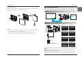
Name of each part
PCB
Front Case Rear Case
ISO View
Side Side
12
ON
34
1
2
3
4
765
8
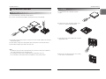
Cable(1 EA)
(For Connecting with indoor unit)
Connector (1 EA)
(For expanding address range)
Installation Manual
* Others :
Screw 4 EA(For installation)
1. CN-OUT :
2. BUS-A :
3. BUS-B :
4. SW1 :
5. SWDIP :
6. LED1 :
7. LED(01~03)G :
8. CN-JIG :
Indoor Unit Connector
RS-485(+) Terminal
RS-485(-) Terminal
Reset Switch
Setting Address Switch(Refer Page 11)
RS-485 Status LED
Communication Status LED
Connector for expanding the address range
Specification
1) Modbus configuration
- Network : 2 wire RS485
- Mode : Modbus RTU slave
- Baud : 9600
- Parity : None
- Stop bits : 1
- Register Base : 0
2) Data registers
※ Above function may not work in some products.
Function code Register Address Name Range Notes
01(read)/05(write) 00001 0x0000 Operation 0~1
0: Stop
1: Run
04(read) 30001 0x0000 Pipe in temprature -300~1120 Degrees (℃) × 10
04(read) 30002 0x0001 Pipe out temperature -300~1120 Degrees (℃) × 10
04(read) 30003 0x0002 Indoor temperature 100~400 Degrees (℃) × 10
04(read) 30100 0x0063 Error code 0~999
0: No error
1~999: Error code
03(read)/06(write) 40001 0x0000 Set run mode (aircon) 0~4
0: Cool
2: Fan
3: Auto
4: Heat
03(read)/06(write) 40002 0x0001 Set temperature 180~300 Degrees (℃) × 10
03(read)/06(write) 40003 0x0002
Set run mode
(ventilation)
0~2
0: Heat exchange
1: Auto
2: Bypass
03(read)/06(write) 40004 0x0003
Set sub operation
(ventilation)
0~2
0: Off
1: Fast
2: Energy saving
03(read)/06(write) 40015 0x000E Set fan speed 1~3
1: Low
2: Middle
3: High
4: Auto
7: Super High

Installation manual 11
Installation Method
10 Modbus Gateway For Indoor Unit
ENGLISH
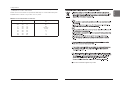
Installation Method
Installation
1) Loosen and remove two screws that secure the
product.
2) Position the rear case to the direction towards to the
connector for convenient cable arrangement.
3) Secure the rear case on the installation place using the
supplied fixing screws.
4) Remove knock out shapes on the rear case according
to the connector’s size and direction.
Installation inside of the indoor unit
1) Loosen and remove two screws that secure the product.
2) Loosen two screws that secure the PCB to separate rear of the case from the PCB.
3) Connect the connection wires properly according to the connection method. (Refer to the instruction
and set-up description)
4) Set the switch according to the setting method. (Refer to the instruction and set-up description)
5) Secure PCB on adequate space inside of the indoor unit.
*Note
1. Install the product on flat surface and install anchoring screws at more than 2 places. Otherwise
the central controller may not be anchored properly.
2. Do not tighten anchoring screws too tightly. It may cause deformation of the case.
3. Do not deform the case at random. It may cause malfunction of the central controller.
Installation Method

Setting method
Installation manual 13
Installation Method
12 Modbus Gateway For Indoor Unit
ENGLISH
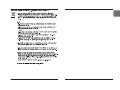
2. Setting Address
After change any Dry contact setting, then you must press RESET switch to reflect the setting.
Indoor unit PCBA
CN_CC
12
ON
34
Modbus
Controller
12
ON
34 12
ON
34
12
ON
34 12
ON
34
12
ON
34 12
ON
34
*Status of switch
- Not attached(default): 1~8
- Attached(expanding address range): 9~16
* /Number: Address when connector is attached
12
ON
34 12
ON
34
Address 1/9 Address 2/10
Address 3/11 Address 4/12
Address 5/13 Address 6/14
Address 7/15 Address 8/16
ON
OFF
12
ON
34
After change any Dry contact setting, then you must press RESET switch to reflect the setting.
h In case, connect a Modbus controller with several product, Address have to be set different from
others.
h If the connector is attached to ‘CN-JIG’, the address range is expanded. (Please attach the
connector before turning on the product.)
5) Connect the connection wires properly according to the connection method. (Refer to the instruction
and set-up description)
6) Set the switch according to the setting method. (Refer to the instruction and set-up description)
7) Tighten the fixing screws on the top and bottom of the case.
*Note
1. Install the product on flat surface and install anchoring screws at more than 2 places. Otherwise
the central controller may not be anchored properly.
2. Do not tighten anchoring screws too tightly. It may cause deformation of the case.
3. Do not deform the case at random. It may cause malfunction of the central controller.
1. Connecting Drycontact with Indoor unit PCBA and Modbus Controller
Setting method

Setting method
14 Modbus Gateway For Indoor Unit Installation manual 15
ENGLISH
※ If the supply cord is damaged, it must be replaced by the manufacturer, its service agent or similarly
qualified persons in order to avoid a hazard.
※ Means for disconnection must be incorporated in the fixed wiring in accordance with the wiring rules.
※ Qualified service technician is only possible to access to product.
Minimum cross-sectional area of conductors
Rated current of appliance
A
Nominal cross-sectional area
mm
2
≤0.2
>0.2 and ≤3
>3 and ≤6
>6 and ≤10
>10 and ≤16
>16 and ≤25
>25 and ≤32
>32 and ≤40
>40 and ≤63
Tinsel cord
a
0.5
a
0.75
1.0 (0.75)
b
1.5 (1.0)
b
2.5
4
6
10
The above information applies only to India.

16 Modbus Gateway For Indoor Unit Installation manual 17
ENGLISH
-
 1
1
-
 2
2
-
 3
3
-
 4
4
-
 5
5
-
 6
6
-
 7
7
-
 8
8
-
 9
9


Ask a question and I''ll find the answer in the document
Finding information in a document is now easier with AI
Related papers
-
LG PDRYCB500.ENCXIDA Installation guide
-
LG PQRSTA0 User manual
-
-
-
LG PAHCMW000 Owner's manual
-
-
LG PMBUSB00A User manual
-
-
LG PAHCNM000 Owner's manual
-
Other documents
-
WAGO 750-341 User manual
-
-
-
-
-
MSA Chillgard® VRF Refrigerant Leak Detector Owner's manual
-
PVI Industries TempTrac Owner's manual
-
Leviton 70N48 User guide
-
Moxa ioLogik E1500 Series User manual
-
Moxa ioLogik E1510-T Specification