Yarway High Pressure Globe Valve, Welbond Model 5600 Owner's manual

Type
Owner's manual

Yarway High Pressure Globe Valve, Welbond Model 5600 is designed for high-pressure applications in modern steam power plants. With its solid stellite seat ring and disc, it offers exceptional wear resistance and durability. The unique six-bladed reseating tool allows for easy restoration of sealing surfaces, extending the valve's lifespan. The fully retractable stellite disc and secondary orifice protect the valve's seat during operation, ensuring reliable performance.

Yarway High Pressure Globe Valve, Welbond Model 5600 is designed for high-pressure applications in modern steam power plants. With its solid stellite seat ring and disc, it offers exceptional wear resistance and durability. The unique six-bladed reseating tool allows for easy restoration of sealing surfaces, extending the valve's lifespan. The fully retractable stellite disc and secondary orifice protect the valve's seat during operation, ensuring reliable performance.

FLOW DIRECTION
ENTERING ABOVE
THE SEAT
VCIOM-02647-EN 18/10Emerson.com/FinalControl
Welbond valves are designed for high pressure,
high temperature service in modern steam
power plants and related installations as
required by the ASME boiler code.
DESIGN FEATURES (FIGURE 1)

the seating surface and throat of the valve
seat without removing the valve body from
the line, producing a completely new sealing
edge on the valve seat.



permanently fused to the valve body.


seat orifice during opening and closing.

gland nuts during repair.




each valve body is machined to accept either
bushing the designs are interchange able and
can easily be converted from one to the other.

ASME Boiler Code; proper drainage in any
line.

operations.
© 2018 Emerson. All Rights Reserved.

Split gland bushing


accessible internals
Gland
Swing bolts

stellite disc
Secondary orifice
Stellite seat ring




bending and thermal distortion giving longer
seatlife.
INSTALLATION
Valves are normally installed with flow entering

flow entering above the seat, when required,

pressure.
Valve should be welded in the line with the disc
in the closed position in order to protect sealing
surfaces from debris and deposits, to prevent
current arcing between disc and seat, and

procedure is dependent upon various codes
established by customers, contractors and/or
government rulings, qualification to the specific
code involved should be followed.
Standard material for forged Welbond valves is

onspecial order can be forged in ASME SA 182


materials is:
 
 
NOTE:

always should be installed with flow entering above
the seat.

above the seat
YARWAY
InstallatIon, oPERatIon anD maIntEnancE manUal
Before installation these instructions must be fully read and understood
2
DISASSEMBLY
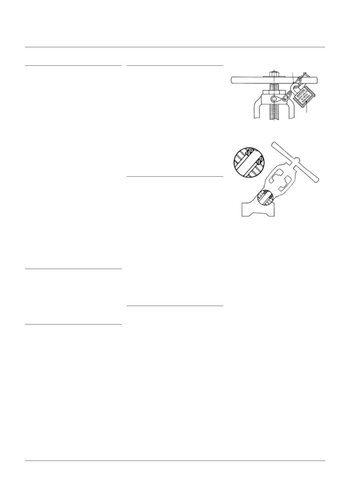
Before attempting disassembly:
CAUTION
Make certain that all line pres sure is relieved and
the pipeline is secured against pressurization.


will contain the letter ‘B’ in the valve figure

letter ‘B’ in the valve figure number.
All internal parts of the Welbond valve may be
removed without disconnecting the body from
the line. When the inside of the valve must be
cleaned or if a foreign body lodged in the valve
prevents proper seating of the disc, proceed as
follows:
LOOSE BACKSEAT DESIGN (FIGURE 3)
 
gland bushing.
 



 


remove the gland.
 

LUBRICATION


and stainless steel stem.
OPERATION
Welbond valves should be opened and closed

service life. Although not specifically a
throttling valve, the Welbond valve will
withstand moderate throttling service due to
the heavy duty stellite seating surfaces and a

some of the pressure drop, thus minimizing
erosion of the primary seating surfaces. When
opening a valve, additional leverage may be
applied only when the valve is first opened to

be opened without additional leverage until firm
resistance is felt when the disc contacts the


given a small additional torque after contact




of additional leverage is not recommended.
An impactor handwheel is furnished on the

to steam gage and water column line service,

with the Boiler Code. Welbond valves can be


CARE OF VALVE

design minimize the effect of debris in the flow
stream, the valve should not be closed against
debris which traps particles between seating

reseating and restoring of the surfaces.


Caution plate


 
 
 
PACKING

by the split gland bushing to prevent stem



are required, compression should be no more


replaced.






YARWAY
InstallatIon, oPERatIon anD maIntEnancE manUal
THREADED-IN BACKSEAT DESIGN (FIGURE 4)



is on the valve identification plate, or the tool
can be selected from the chart on the opposite
page which also gives the tool part number.
 
number corresponds with the valve size
number appearing in selector chart.
2. Before disassembly, be sure valve is not
under pressure.
 


remove bushing.

the bolts free of gland.

bushing.
 


holes are aligned.

remover.


tool teeth and repeat cutting.
e. Remove tool by turning handle




 



are aligned with shaft firmly pressed
downward.



bushing is completely unthreaded,


 

removed also. Remove gland.


 
 
 

Handle
Sleeve
Stem


remover

Shaft

support ring

bushing &


removal tool

tool
YARWAY
InstallatIon, oPERatIon anD maIntEnancE manUal
4
   
   
   
   
   
   
¾
   
   
   
   
   
   
1
  40 
  40 
   
   
   
   

   
   
   
   
   
2
  42 
   
   
  42 
   

   
   
   
   
   
INSPECTION AND REPAIR


completely disassembled.

threads must be free of burrs to assure free
operation, and stem shaft should be smooth
and free of gouges, grooves or burrs to insure a
tight valve shutoff.
Replace the entire stem and disc assembly if
either is damaged.

When there is evidence of gouges, grooving,

indicating seat ovality, the solid satellite seat
should be reconditioned by recutting. Welbond
valve seats should not be lapped to the disc.
PACKING AND BACKSEAT REMOVAL TOOL SELECTION
Valve size NPS Valve fig No. Pressure class Indent tool No. Tool part No.
YARWAY
InstallatIon, oPERatIon anD maIntEnancE manUal

   
¾    
1 20  20 
    
2 22   
   28 
  28 

   
¾    
1 20  20 
    
2    
   28 
  28 

   
¾    
1    
   21 
2   21 

  20 
¾   20 
1   20 
RESEATING

allow recutting of worn or damaged seats
without removing the valve body from the line.
Cutters of various sizes assure that all Welbond
valve seats are cut at the correct angle.


from the following chart which also gives the

seat is a very hard material requiring carbide
cutters. Handle carbide cutters with great care
to prevent edge chipping. Jamming the carbide
cutters against the valve seat can cause cutter
chipping or fracturing of the hard stellite seat.
Proceed with caution as follows:
 

2. Rotate feed screw carefully until cutter
lightly contacts valve seat. When contact
is felt, hand tighten feed screw using


 

Rotate the handwheel as smoothly as
possible through at least three revolutions
to finish the cutting action.
 
and clean cutter of chips.
 
surface.
Repeat steps 1 through 4 if necessary to obtain
a satisfactory reconditioned seat.

Cutter
Stellite seat
Handwheel


RESEATING TOOL SELECTION
Valve fig No. Valve size NPS Tool No. Tool part No. Cutter No. Cutter part No.
YARWAY
InstallatIon, oPERatIon anD maIntEnancE manUal
45°

  
1  
  
  
2  
  
  
  
LOOSE BACKSEAT DESIGN
 


into valve body.
 

 
then evenly tighten gland bolts.
 
clear of valve seat. Redeposit sufficient weld


 
PACKING INSTALLATION
 
any spacers, washers or lantern rings, if


and stem for straightness, wear, scratches,
pitting and other abnormalities which would
prevent establishment of a good seal around

 

 IMPORTANT:
complete set and rings should be installed

are either one piece solid or in a split form.

to facilitate installation. Rings should be
cut using a razor blade or other similar thin




REASSEMBLY, THREADED-IN BACKSEAT
DESIGN
 




gland into valve.
 


engagement.

are aligned with sleeve firmly pressed
downward.


using torque values given below:
 
 
 

 
then evenly tighten gland bolts.
 
clear of valve seat. Redeposit sufficient weld


8. Reassemble handwheel.

TORQUE VALUES
Valve size
Backseat bushing
Class ft·lb (Nm)
YARWAY
InstallatIon, oPERatIon anD maIntEnancE manUal
C
B
A
 
to slip the rings over the stem without
opening the rings, install the rings over
the stem by twisting open in an ‘S’ fashion.


 

 

gland bushing. Each ring must be seated

CAUTION:
do not use a screw driver or other sharp object to
seat the packing. This could damage the packing
and/or stem. If a packing d river is used, make
sure the diametrical clearances between the I.D.
of the driver and O.D. of the stem and, the O.D.
of the driver and I.D. of the stuffing box do not
exceed 0.20”. See Fig. 7c.
 


 
number of rings may require some
compression of the rings already installed.

amount of compression should be only
that which is required to install the correct




Wrong
Right




Stem




gland nuts.
 


on the gland nuts evenly with a wrench to





move the stem to insure no binding is

plus ¼ turn.

necessary after a few hours of service.
YARWAY
InstallatIon, oPERatIon anD maIntEnancE manUal
8

Responsibility for proper selection, use, and maintenance of any product remains solely with the purchaser and end user.




our terms and conditions, which are available upon request. We reserve the right to modify or improve the designs or specifications of such products at any time without
notice.

  • Page 1 1
  • Page 2 2
  • Page 3 3
  • Page 4 4
  • Page 5 5
  • Page 6 6
  • Page 7 7
  • Page 8 8

Yarway High Pressure Globe Valve, Welbond Model 5600 Owner's manual

Type
Owner's manual

Yarway High Pressure Globe Valve, Welbond Model 5600 is designed for high-pressure applications in modern steam power plants. With its solid stellite seat ring and disc, it offers exceptional wear resistance and durability. The unique six-bladed reseating tool allows for easy restoration of sealing surfaces, extending the valve's lifespan. The fully retractable stellite disc and secondary orifice protect the valve's seat during operation, ensuring reliable performance.

Ask a question and I''ll find the answer in the document

Finding information in a document is now easier with AI