Page is loading ...

MSAsafety.com
User Instructions
MSA Rail Slider™ Anchorage Connector
Doc./Mat.: SSRS001/08
Print Spec.: 10000005389 (F)
CR 800000039441
Model Number / Numero de modelo /
Numero de modele

WARNING!
National standards and state, provincial and federal laws require the user
to be trained before using this product. Use this manual as part of a user
safety training program that is appropriate for the user's occupation. These
instructions must be provided to users before use of the product and
retained for ready reference by the user. The user must read, and under-
stand (or have explained), and heed all instructions, labels, markings and
warnings supplied with this product and with those products intended for
use in association with it. FAILURE TO DO SO MAY RESULT IN SERIOUS
INJURY OR DEATH.
MSA, MSA The Safety Company, and the MSA The Safety Company Logo are Registered Trademarks
of MSA Technology, LLC in the U.S. and/or Other Countries. For all other trademarks see
https://us.msasafety.com/Trademarks
1000 Cranberry Woods Drive
Cranberry Township, PA 16066
USA
Phone 1-800-MSA-2222
Fax 1-800-967-0398
For your local MSA contacts please go to our website www.MSAsafety.com
©
MSA 2020. All rights reserved

MSA Rail Slider™ Anchorage Connector
3
Safety Regulations
US
1 Safety Regulations
1.1 Correct Use
The MSA Rail Slider Anchorage Connector is designed for use by one person working at an elevated
work level. The MSA Rail Slider Anchorage Connector links the user to a rail anchorage point. It allows
the worker to utilize existing rails as temporary anchors, without the need for drilling or permanently
attaching anchorages. It moves with the worker allowing for continuous tie off.
1.2 Compliance
The product may comply with:
• ANSI Z359.18, Type A and / or;
• OSHA requirements
See product label for specific compliance notifications.
Anchorage connectors labeled with ANSI Z359.18 have been tested in compliance with the require-
ments of ANSI/ASSE Z359.7.
NOTICE
ANSI compliance and testing covers only the hardware and does not extend to the anchorage and
substrate to which the anchorage connector is attached.
1.3 Usage Specifications
• The MSA Rail Slider Anchorage Connector is capable of withstanding a load of 5,000 lbf (22.2 kN)
without breaking or permanent deformation.
• The MSA Rail Slider Anchorage Connector is designed for the attachment of a single personal fall
arrest system.
• Weight: 6,0 lbf (2,9 kg)
• Materials of construction: SA516 Grade 70 Steel
• When used as part of a personal fall arrest system, fall arresting forces must not exceed 1,800 lbf
(8 kN).
• The Rail Slider Anchorage Connector is designed for use by one person. See instructions and
labels on each fall protection subsystem component to determine the limiting user weight capacity
of the system.

MSA Rail Slider™ Anchorage Connector
4
Safety Regulations
US
1.4 Safety and Precautionary Measures
WARNING!
DO NOT exceed the allowable free fall distance or exceed the maximum fall arrest forces as spec-
ified by governing standards or subsystem components.
The anchorage to which the MSA Rail Slider Anchorage Connector Strap is attached must be
rated in the direction of intended use. See sections 2.2 "Anchorages and Anchorage Connectors"
and 3 "Use" for details on anchorage strength and loading details.
When installing or removing the MSA Rail Slider Anchorage Connector Strap limit exposure to fall
hazards. A separate independent fall arrest system may be required.
Ensure that fall clearance is sufficient to meet governing standards or subsystem component
requirements.
Prevent swing falls and impact with objects in or adjacent to the fall path. Always remove obstruc-
tions below the work area to ensure a clear fall path. Keep work area free from debris, obstruc-
tions, trip hazards, spills or other hazard which could impair the safe operation of the fall protection
system. DO NOT use the MSA Rail Slider Anchorage Connector Strap unless a qualified person
has inspected the workplace and determined that identified hazards can neither be eliminated nor
exposures to them prevented.
Work directly under the anchorage/anchorage connector at all times. A full body harness is the
only acceptable body holding device that can be used in a fall arrest system.
DO NOT rely on feel or sound to verify proper snaphook or carabiner engagement. Ensure that
gate and keeper are closed before use.
If the MSA Rail Slider Anchorage Connector Strap is damaged or is subjected to fall arrest forces
or impact forces, it must be immediately removed from service and marked as "UNUSABLE" until
it has been destroyed.
DO NOT leave the MSA Rail Slider Anchorage Connector Strap installed in environments which
could cause damage or deterioration to the product. Refer to sections 4 "Care, Maintenance and
Storage" and 5 "Inspection" for care and inspection details. Do not leave unattended loads on the
MSA Rail Slider Anchorage Connector Strap.
DO NOT use where lanyard or shock absorber may be exposed to sharp or abrasive edges or
sheared, expanded metal, or frame cut steel. Sharp edges may cut a lanyard or shock absorber
during a fall. Cover all sharp or abrasive edges with padding or sheathing before working above
edge.
Chemical hazards, heat and corrosion may damage the MSA Rail Slider Anchorage Connector
Strap. More frequent inspections are required in these environments.
DO NOT use MSA Rail Slider Anchorage Connector Strap adjacent to moving machinery, elec-
trical hazards, or in the presence of excessive heat, open flame or molten metal.
DO NOT use fall arrest or rescue equipment in environments with temperatures greater than
130°F (34°C) or temperatures lower than -30°F (-34°C).
DO NOT use the MSA Rail Slider Anchorage Connector Strap near energized equipment or where
contact with high voltage power lines may occur. The metal cable may provide a path for electrical
current to flow, resulting in an electrical shock or electrocution.
Remove any surface contamination such as, but not limited to, concrete, stucco, roofing material,
etc that could accelerate cutting or abrading of attached components.
MSA Rail Slider Anchorage Connector Straps are to be designated and used solely for approved
applications.
Unauthorized alterations, relocations, or additions to the anchorage connector extension are not
permitted.

MSA Rail Slider™ Anchorage Connector
5
Safety Regulations
US
DO NOT alter this equipment or intentionally misuse it. DO NOT use fall protection equipment for
purposes other than those for which it was designed. DO NOT use fall protection equipment for
towing, hoisting or material handling.
If PPE is resold, it is essential that instructions for use, maintenance, and periodic examination are
provided in the language of destination.
DO NOT use MSA Fall Protection products if under the influence of drugs or alcohol.
MSA or persons or entities authorized in writing by the manufacturer, shall make all repairs to the
equipment. No unauthorized repairs and/or modifications are permitted.
RESCUE AND EVACUATION: The user must have a rescue plan and the means at hand to imple-
ment it. The plan must take into account the equipment and special training necessary to effect
prompt rescue under all foreseeable conditions. If the rescue be from a confined space, the provi-
sions of OSHA regulation 1910.146 and ANSI Z 117.1 must be taken into account. Although a
rescue plan and the means to implement it must always be in place, it is a good idea to provide
means for user evacuation without assistance of others. This will usually reduce the time to get to
a safe place and reduce or prevent the risk to rescuers.
Failure to follow these warnings can result in serious personal injury or death.
1.5 Usage Limitations
1.5.1 Environment
Chemical hazards, heat and corrosion may damage the PointGuard Anchorage Connector Strap. More
frequent inspections are required in these environments. Do not use in environments with tempera-
tures greater than 130°F (34°C). Use caution when working around electrical hazards, moving
machinery, abrasive surfaces, and sharp edges.
1.6 Training
Users of MSA Products must be familiar with the User Instructions and be trained by a competent
person in:
• workplace hazard identification, evaluation and control
• selection, inspection, use, storage and maintenance
• usage planning including calculation of free and total fall distance; maximum arresting force
• compatibility and selection of anchorage/anchorage connectors including connection to help
prevent accidental disengagement (rollout)
• proper lanyard/harness connection locations
• evacuation and rescue planning and implementation
• consequences of improper use
For Confined Space applications:
• See OSHA 29 CFR 1910.146 and ANSI Z117.1.
Periodically (at least annually) assess effectiveness of training and determine the need for retraining
or additional training. Contact MSA for training information.

MSA Rail Slider™ Anchorage Connector
6
Safety Regulations
US
1.7 Warranty
Express Warranty – MSA warrants that the product furnished is free from mechanical defects or
faulty workmanship for a period of one (1) year from first use or eighteen (18) months from date of
shipment, whichever occurs first, provided it is maintained and used in accordance with MSA’s
instructions and/or recommendations. Replacement parts and repairs are warranted for ninety (90)
days from the date of repair of the product or sale of the replacement part, whichever occurs first.
MSA shall be released from all obligations under this warranty in the event repairs or modifications
are made by persons other than its own authorized service personnel or if the warranty claim results
from misuse of the product. No agent, employee or representative of MSA may bind MSA to any affir-
mation, representation or modification of the warranty concerning the goods sold under this contract.
MSA makes no warranty concerning components or accessories not manufactured by MSA, but will
pass on to the Purchaser all warranties of manufacturers of such components. THIS WARRANTY IS
IN LIEU OF ALL OTHER WARRANTIES, EXPRESS, IMPLIED OR STATUTORY, AND IS STRICTLY
LIMITED TO THE TERMS HEREOF. MSA SPECIFICALLY DISCLAIMS ANY WARRANTY OF
MERCHANTABILITY OR FITNESS FOR A PARTICULAR PURPOSE.
Exclusive Remedy - It is expressly agreed that the Purchaser’s sole and exclusive remedy for
breach of the above warranty, for any tortious conduct of MSA, or for any other cause of action, shall
be the repair and/or replacement, at MSA’s option, of any equipment or parts thereof, that after exam-
ination by MSA are proven to be defective. Replacement equipment and/or parts will be provided at
no cost to the Purchaser, F.O.B. Purchaser’s named place of destination. Failure of MSA to success-
fully repair any nonconforming product shall not cause the remedy established hereby to fail of its
essential purpose.
Exclusion of Consequential Damages Purchaser specifically understands and agrees that under
no circumstances will MSA be liable to Purchaser for economic, special, incidental, or consequential
damages or losses of any kind whatsoever, including but not limited to, loss of anticipated profits and
any other loss caused by reason of the non-operation of the goods. This exclusion is applicable to
claims for breach of warranty, tortious conduct or any other cause of action against MSA.
For additional information please contact the Customer Service Department at 1-800-MSA-2222
(1-800-672-2222).

MSA Rail Slider™ Anchorage Connector
7
Description
US
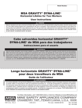
2 Description
The MSA Rail Slider Anchorage Connector device can be installed anywhere along an approved
anchorage (rail). The slider will move along the rail, pulled by the worker’s lanyard/harness. No
unhooking and re-hooking of the lanyard is required when changing work locations. The Rail Slider
device consists of a pair of rail profile plates, which interlock via a set of receiving bolts. A lanyard is
attached to an approved carabiner securing the profile plates to the crown of the rail.
Fig. 1 Range of allowable loading direction.
2.1 System Requirements
2.1.1 Compatibility of Components and Subsystems
MSA Rail Slider Anchorage Connector are designed to be used with MSA approved components and
connecting subsystems. Use of the MSA Rail Slider Anchorage Connector with products made by
others that are not approved in writing by MSA may adversely affect the functional compatibility
between system parts and the safety and reliability of the complete system. Connecting subsystems
must be suitable for use in the application (e.g. fall arrest or restraint). MSA produces a complete line
of connecting subsystems for each application. Contact MSA for further information. Refer to the
manufacturer’s instructions supplied with the component or connecting subsystem to determine suit-
ability. For fall arrest applications using the MSA Rail Slider Anchorage Connector, the maximum fall
arrest force must not exceed 1,800 lbf (8 kN). Contact MSA with any questions regarding compatibility
of equipment used with the MSA Rail Slider Anchorage Connector.
2.1.2 Compatibility of Connectors
Connectors, such as D-rings, snaphooks, and carabiners, must be rated at 5,000 lbf (22 kN) minimum
breaking strength. MSA connectors meet this requirement. Connecting hardware must be compatible
in size, shape, and strength. Non-compatible connectors may accidentally disengage (“rollout”).
Always verify that the connecting snaphook or carabiner and the D-ring on the harness or anchorage
connector are compatible. Use only self-closing, self-locking snaphooks and carabiners with the MSA
Rail Slider Anchorage Connector.

MSA Rail Slider™ Anchorage Connector
8
Description
US
2.1.3 Anchorages
Anchorages for personal fall arrest systems must either: (a) have a strength capable of supporting and
withstanding at least 5,000 pounds (22.2 kN) in the directions permitted by the system without failure,
or (b), must be certified by a professional engineer as having the required strength for fall arrest or
travel restraint, as applicable. See ANSI Z359.18 for definition of certification. When more than one
personal fall arrest system is attached to an anchorage, the anchorage strengths set forth in (a) and
(b) must be multiplied by the number of systems attached to the anchorage. This requirement is consis-
tent with OSHA requirements under 20 CFR 1910, Subpart F, Section 1910.66, Appendix C. Do not
proceed with installation and use of the anchorage connector if an assessment of strength cannot be
made.
2.2 Markings and Labels
The preceding labels must be present, legible and securely attached to the MSA Rail Slider
Anchorage Connector. The labels are located on the sides of the profile plates.

MSA Rail Slider™ Anchorage Connector
9
Description
US

MSA Rail Slider™ Anchorage Connector
10
Description
US
2.3 Liability Information
MSA accepts no liability in cases where the device has been used inappropriately or not as intended.
The selection and use of the device are the exclusive responsibility of the individual operator.
Product liability claims, warranties and guarantees made by MSA with respect to the device are voided,
if it is not used, serviced or maintained in accordance with the instructions in this manual.

MSA Rail Slider™ Anchorage Connector
11
Use
US
3 Use
3.1 Planning the Use of Systems
3.1.1 Free Fall Distance, total Fall Distance, and System Elongation
Refer to separate user instructions accompanying the personal energy absorber (shock absorbing
lanyard or self-retracting lanyard) to determine total system clearance requirements.
3.1.2 Pendulum (swing) Falls
Swing fall hazards must be minimized by anchoring directly above the user’s work space. The force of
striking an object in a pendular motion can cause serious injury. Always minimize swing falls by working
as directly below the anchorage point as possible.
3.2 Inspection Before Each Use
Inspect the MSA Rail Slider Anchorage Connector to verify it is in serviceable condition. Examine entire
device for signs of cracking or deformation. See section 5 for inspection details. Do not use a MSA
Rail Slider Anchorage Connector if inspection of it reveals an unsafe condition.
3.3 Making Connections
To reduce the possibility of rollout use only self closing, self locking carabiners. Do not use carabiners
that will not completely close over the attachment object. Do not make knots in a lanyard. Do not hook
a lanyard back onto itself. Carabiner may only be connected through the closed eye of the Rail Slider
(See Fig. 6 ). Do not attach two snaphooks into one carabiner. Always follow the manufacturer’s
instructions supplied with each system component.
3.4 Inspecting the MSA Rail Slider Anchorage Connector
WARNING!
Make certain rail head is not worn beyond proper fit limits, as stated, along the entire length of the rail
on which the Rail Slider is to be used. Rail worn beyond fit limits will result in inadequate fall arrest
protection as designed.
Do not use on "head-free" rail.
Do not install where rail slider could contact equipment on the same rail,
Failure to follow these warnings can result in serious personal injury or death.
NOTE: The MSA Rail Slider Anchorage Connector may be attached to rails specified in the following
table.
(1) Ensure that the Rail Slider part number matches the rail size in the following table. Do not use if
the Rail Slider part number does not match the rail size.
(2) Inspect the rail slider by placing the Rail Slider profile plate on the crown of the rail section.
(3) Check the width of the rail head along the entire length of the rail on which the Rail slider is to
be used. The width at the bottom of the rail head (Dimension “A”) must be greater than or equal
to the value shown in the table below. If “A” is less than specified, DO NOT USE Rail Slider.
Part Number Description Rail Size Dimension A
SFPRS6000 136 lb (62 kg) slider 85-136 lbs/yds 2.5” (63.5 mm) MIN
SFPRS6000RR 136 lb (62 kg) slider 85-136 lbs/yds 2.5” (63.5 mm) MIN
SFPRS7000 175 lb (88 kg) slider 175 lbs/yds 4.0” (101.6 mm) MIN
SFPRS8000 171 lb (86 kg) slider 171 lbs/yds 4.05” (102.86 mm) MIN
10030608 141 lb (64 kg) slider 90-141 lbs/yds 2.56” (65.0 mm) MIN
10105297 40 lb (18 kg) slider 30-40 lbs/yds 1.68” (42.67 mm) MIN
10111223 60 lb (30 kg) slider 60 lbs/yds 2.138” (54.31 mm) MIN
10116712 135 lb (67 kg) slider 135 lbs/yds 3.438” (87.32 mm) MIN
10119225 20 lb (9 kg) slider 20 lbs/yds 1.21” (30.73 mm) MIN

MSA Rail Slider™ Anchorage Connector
12
Use
US
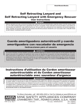
Fig. 2 Check width of the rail head
Fig. 3 Profile plates flush with each
other
(4) Align the second Rail Slider profile plate with the
first plate. Permit passage of the receiving bolts,
the top flat section of the profile plates shall be
flush with each other.
Fig. 4 Profile plates are locked
(5) Once the profile plates are flush with each other,
slide each plate in opposite directions parallel to
the rail. The plates are now locked on the crown
of the rail.
MEASURE WIDTH OF RAIL
HEAD AT THIS POINT.
WORN HEAD OF RAIL

MSA Rail Slider™ Anchorage Connector
13
Use
US
CAUTION!
Check for proper fit along the entire length of the rail the device is to be used on.
(8) The MSA Rail Slider is now functional.
(9) To remove the Rail Slider from the rail, follow the Connecting Instructions in reverse.
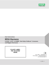
Fig. 5 Profile plates are locked and
secured
(6) Attach an approved carabiner (Autolock) into
the attachment hole.The recommended cara-
biner for use with the Rail Slider is SRCC643;
acceptable substitutes are, 10046182,
10089207, and 10089209. Once the carabiner
is locked in place the profile plates are now
locked and secure.
Fig. 6 Carabiner connected through the
closed eye of the Rail Slider
(7) Attach an approved lanyard/harness to the
carabiner. Ensure that the hardware is compat-
ible.
ONLY USE APPROVED HARDWARE.
Approved lanyards must end in one of the
following connections; SRCC643, 10046182,
10088270, 10088291, 10089159, 10089205,
10089207, or 10089209.

MSA Rail Slider™ Anchorage Connector
14
Care, Maintenance and Storage
US
3.5 Moving around the Work Area
WARNING!
DO NOT exceed the allowable free fall distance as specified by governing standards or subsystem
components.
DO NOT exceed the maximum fall arrest forces as specified by governing standards or subsystem
components.
Failure to follow these warnings can result in serious personal injury or death.
The MSA Rail Slider Anchorage Connector is designed to move along the rail anchorage, following the
user movements. Move around carefully to prevent loss of balance in the event the MSA Rail Slider
Anchorage Connector binds or contacts an obstacle in the path of movement.
4 Care, Maintenance and Storage
4.1 Cleaning Instructions
Use a clean damp (not wet) cloth to remove dirt or contamination which may cause corrosion or
hamper readability of labels. Wipe off any moisture before returning the device to service. The
frequency of cleaning should be determined by inspection and by severity of the environment. In highly
corrosive environments cleaning should be done every two or three days. Never use solvents to clean
the device as they may damage the labels. Don’t use abrasives to scour the device as they may
damage the surface and the labels. To remove oil or grease, use a mild dishwater detergent on a damp
cloth or sponge and follow by repeated swabbing with a clean cloth to remove all soap residue. Never
immerse the product in water or other liquid.
4.2 Storage
Store the device in a clean, dry place indoors. Store the product away from heat and steam and never
allow it to rest for lengthy periods of time on concrete or ash floors as the lime sulfur and ash can cause
corrosion.
4.3 Maintenance and Service
User maintenance consists of cleaning and drying the device. All other maintenance or repair/work
must be done at the factory or by an authorized person. (Authorization by MSA must be written.)

MSA Rail Slider™ Anchorage Connector
15
Inspection
US
5 Inspection
5.1 Inspection Frequency
The MSA Rail Slider Anchorage Connector must be inspected by the user before each use and, addi-
tionally, by a competent person other than the user at intervals of no more than six months. The compe-
tent person inspection is referred to as Formal Inspection.
The program administrator shall maintain documentation of equipment inspections. This documenta-
tion shall include, at a minimum, the identity of the equipment, inspection date, name of the competent
or qualified person conducting the inspection and the result of that inspection.
The program administrator shall set inspection criteria for the equipment. Such criteria shall equal or
exceed the most restrictive of the criteria established by the ANSI Z359.18 standard or the manufac-
turer‘s user instructions. Keep inspection criteria current in relationship to changing patterns or condi-
tions of use.
5.2 Inspection Steps
Perform the following steps in sequence. If in doubt about any inspection point, consult MSA or a
competent person who is qualified to perform Formal Inspection as set forth in section 5.4 .
(1) Inspect the MSA Rail Slider Anchorage Connector labels to verify that they are present and
legible.
a) See section 2.2 for the specific labels that should be present and the information contained
thereon.
b) Check the Formal Inspection Log to be sure a Formal Inspection has been performed within
the last six months. If the Log does not indicate that a Formal Inspection has been performed
within the last six months, or if any labels are missing or illegible, remove the device from
use and mark it as “UNUSABLE” until a Formal Inspection is performed by a competent
person.
(2) Remove Rail Slider from service immediately if:
a) The product has been subjected to the forces of a fall.
b) There is evidence of improper function or alterations of any portion.
c) If inspection reveals evidence of structural damage, cracks, deformations, or excessive
corrosion.
(3) Inspect each component and subsystem of the complete system in accordance with the associ-
ated manufacturer’s instructions.
(4) Both halves of the Rail Slider are marked with a distinct serial number. When inspecting, ensure
both halves have the same serial number.

MSA Rail Slider™ Anchorage Connector
16
Inspection
US
NOTE: Opening to be measured at each end with application of nominal spreading force of the hand.

MSA Rail Slider™ Anchorage Connector
17
Inspection
US
1 DIM “B”
2 Rounded portion of Rail Slider must be below edge of rail head.
3 MINIMUM MATERIAL THICKNESS: 3/16” (5 mm)
4 excessive wear
5 Minimum material thickness: 3/16” (5mm)
Remove device from service if material thickness is less than 3/16” (5 mm).
6 Ensure that bottom tip of Rail Slider will be below the side of the rail head.
The tip must not be adjacent to the side of the head of the rail when the slider is lifted as shown.
7 Check width opening of Rail Slider.
The distance between the tips (Dimension B) must be within the range provided in the table below.

MSA Rail Slider™ Anchorage Connector
18
Inspection
US
5.3 Corrective Action
When inspection in accordance with section 5 "Inspection" reveals any of the identified conditions, the
MSA Rail Slider Anchorage Connector must be immediately removed from service and marked as
"UNUSABLE" until destroyed or subjected to corrective maintenance by the user's organization in
accordance with this user instruction. Damage, excessive wear, malfunction, and aging are generally
not repairable. If detected, immediately remove the MSA Rail Slider Anchorage Connector from use
and mark it as "UNUSABLE' until destroyed. For final disposition, submit the MSA Rail Slider
Anchorage Connector to a competent person who is authorized to perform Formal Inspection. If there
is any question as to repairability, contact MSA or a service center authorized in writing by MSA before
further use of the product.
WARNING!
Unauthorized alterations, relocations, or additions to the MSA Rail Slider Anchorage Connector are not
permitted. Only MSA or persons or entities with written authorization from the manufacturer may make
repairs to the MSA Rail Slider Anchorage Connector. No unauthorized repairs, modifications, alter-
ations, relocations, and/or additions are permitted. Failure to follow this warning can result in serious
personal injury or death.
5.4 Inspection Log
Part Number Dimension B
SFPRS6000 1.32” (33.5 mm) MIN 1.5” (38.1 mm) MAX
SFPRS6000RR 1.32” (33.5 mm) MIN 1.5” (38.1 mm) MAX
SFPRS7000 2.69” (68.32 mm) MIN 3.2” (81.28 mm) MAX
SFPRS8000 2.69” (68.32 mm) MIN 2.82” (71.62 mm) MAX
10030608 1.32” (33.5 mm) MIN 1.563” (39.7 mm) MAX
10105297 0.56” (14.2 mm) MIN 0.68” (17.27 mm) MAX
10111223 0.65” (16.5 mm) MIN 0.77” (19.55 mm) MAX
10116712 1.63” (41.4 mm) MIN 1.74” (44.19 mm) MAX
10119225 0.34” (8.63 mm) MIN 0.46” (11.68 mm) MAX
Model No.: Inspector:
Serial No.:
Inspection
Date:
Date Made: Disposition:
Comments:

MSA Rail Slider™ Anchorage Connector
19
Inspection
US
5.5 Inspection Diagram
1 Side Plate - 2 4 ID Label - 1
2 Nut - 2 5 Warning Label - 1
3 Pin - 2

For local MSA contacts, please visit us at MSAsafety.com
/