Page is loading ...

KEYSTONE RMI DUBEX BUTTERFLY VALVES
InstallatIon and MaIntenance InstructIons
INTENDED VALVE USE
The valve is intended to be used only in
applications within the pressure/temperature
limits indicated in the P/T diagram of the
product manual.
1 STORAGE AND HANDLING
1.1 Storage
When valves are to be stored for some time
(2months or more) before being fitted, storage
should be in the original delivery crates or
cases.
1.1.1 Storage conditions
The valves should be stored off the ground in a
clean, dry indoor area.
Protect the valve from temperature and
humidity extremes, and exposure to excessive
dust, moisture, vibration, deformations,
sunlight and ozone.
Please read these instructions carefully
VCIOM-02129-EN 14/07
Recommendations
1. Temperature: storage temperature
below25°C, above 0°C preferable
below15°C.
2. Humidity: storage conditions should be such
that condensation does not occur, store in
a dry environment. Maximal 50% relative
humidity.
3. Light: valve rubbers should be protected
from light, in particular direct sunlight or
strong artificial light with high ultra violet.
4. Ozone: storage rooms should not
contain any equipment generating ozone.
E.g.lamps, electric motors.
IMPORTANT
Before valves are being installed or used the
following actions are recommended.
1. Valves/parts have to be inspected and
thoroughly cleaned if required.
2. Rubber parts need to be greased with silicone
grease if not present anymore.
3. All surfaces in contact with seats have to be
thoroughly cleaned and greased with silicone
grease if stored for more than 5 months.
1.2 Handling
To prevent damage during lifting, the valves
should be lifted by hand or with appropriate
lifting equipment. The valves should be
protected from external events e.g. (bumps,
hitting and vibration) during transport.
Any flange protection caps need to be removed
before the valve is mounted in the pipeline.
Lift the valve with great care from the transport
package (crate, pallet). While handling or
installing the valve, ensure that no damage
occurs to the valve, the pneumatic/electrical/
hydraulic actuator or other instrumentation.
2 SPARE PARTS
Only original RMI spare parts are allowed to be
used. Safe operation can not be guaranteed if
third party spare parts are used.
www.valves.emerson.com © 2017 Emerson. All rights reserved.

2
KEYSTONE RMI DUBEX BUTTERFLY VALVES
InstallatIon and MaIntenance InstructIons
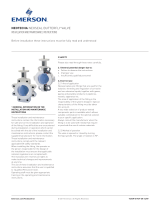
D max/min
Q
Size
Unidirectional or
Bidirectional
Material
identification
Sales order nr.
Figure
3 INSTALLATION
WARNING
For safety reasons, it is important to take the
following precautions before starting to work on
the valve:
1. Personnel making any adjustments to the
valves should utilize suitable equipment. All
required personal protection means should be
worn.
2. The line must be depressurized before
installing the valve.
3. Installation and handling of valves should be
done only by personnel that is trained in all
aspects of manual and mechanical handling
techniques.
4. Misuse of the valve is not allowed.
Forexample: the valve, handles, actuators
or other parts may not be used as
‘climbingtools’.
5. Ensure that valve pressure/temperature
limitations marked on the valve’s tagplate
are within the service conditions. The trim
number on the valve’s tagplate identifies
the valve materials. See Product Manual for
valve specific P/T diagram and trim number
definition.
6. Ensure that valve materials are compatible
with the pipeline fluid.
3.1 Visual valve inspection
1. Confirm that the materials of construction
listed on the valve tagplate are appropriate
for the service intended and are as
specified.
2. Tag/name plate identification
Manufacturer: Emerson RMI
Figure: Dubex
Material trim: e.g. 804
Direction: U(nidirectional) or
B(idirectional)
Size: e.g. DN 1000
Tag no.: if required
Design pressure: e.g. PN 16
Design temperature: e.g. 20°C
Year of construction: e.g. 2004
Mass: e.g. 2500 kg
3.2 Flange and pipe compatibility
Check matching of flange drilling pattern of
valve and pipe before assembly.
Flanges have to meet the following
requirements:
- The face inside diameter should be:
D min.: The valve Q-dimension + adequate disc
clearance.
D max.: The inside diameter (ID) of standard
pipe for the nominal size ISO 4200.
Use flange bolting in agreement with
appropriate standard.
3.3 Valve installation
The valves are delivered as uni- or bidirectional.
An uni-directional valve is equipped with an
arrow on the body. The arrow points from
the high pressure side to the low pressure
side. The preferred direction in the pipeline is
positioning the valve with the seat downstream
of the shaft valve. The valve will control flow
not exactly equal in both directions. The
recommended installation position is shaft
horizontal and the lower disc edge opening
downstream (especially for slurry service and
media with a tendency for sedimentation).
For optimum valve control and smooth
performance, it is recommended to have 10 to
20 pipe diameters of straight run inlet piping
and 3 to 5 pipe diameters straight outlet piping.
Do not use the valve to spread the flanges.

3
NOTES
• The valve can be installed in the pipe-line either with
or without the actuator mounted on the valve. Make
sure that you can turn the disc so you can check on
interference of the disc with the adjacent piping.
• Do not use the valve as a support for the pipeline
construction.
• Adjacent piping must be positioned so that minimal
piping stresses are transmitted to the valve flanges
during or after installation.
• Handling and lifting of the valves during installation
MUST be performed following the same instructions
described in previous section ‘1.2 Handling’.
IMPORTANT
Mating flange faces should be in good condition
and free of dirt and/or inclusions. Both pipe
insides to be well cleaned.
1. Check whether the distance between
flanges meets the face-to-face valve
dimensions. Spread the flanges with
adequate tooling for easy insertion of the
valve.
2. Close the valve so that the disc is at least
10mm within the valve face.
3. Insert the valve with the gaskets between
the flanges. Center the valve body and insert
all flange bolts.
4. Maintain the valve flange alignment while
gradually removing the flange spreaders
and tighten the flange bolts hand tight.
5. Slowly open and close the valve to check
for adequate disc clearance. Do not close
the valve in dry condition. Coat the seat with
silicon grease if no water is available.
6. Cross tighten all bolting to the proper
torque.
3.4 Valve verification
Check the operation of the valve by operating
it to ‘full open’ and ‘full close’ to verify the
valve operation. The disc position indicator on
the actuator or the manual operator should
rotate between the ‘full open’ and ‘full close’
indicators. The valve disc rotates clockwise to
close. Do not close the valve in dry condition,
use silicon grease if no water is available.
3.5 Sources of possible danger
This section contains some examples of
possible foreseen danger sources.
3.5.1 Mechanical
When manual operators are used, available
space should be checked in order to avoid
hands being clamped.
Mechanical sparks caused on impact of valve
and e.g. tooling are a potential source of
ignition of surrounding atmosphere.
3.5.2 Electrical
If static charges or stray electrical currents
can initiate explosions the valve should be
grounded.
3.5.3 Thermal
If the valve is used in applications with a fluid
temperature > +40°C and < -20°C, the outside
of the body should be protected by means of
isolation against touching to avoid burning.
In case the valve is used in hot gas/fluid
applications that might give exothermic
reactions, precautions must be taken so that
the valve surface can not lead to danger for
people or the direct environment.
3.5.4 Operational
Closing a valve too fast may result in
waterhammer in the upstream part of the
pipeline. Waterhammer results in excessive
stresses in the valve and will cause severe
damage. Waterhammer should be avoided in all
circumstances.
Due to differential pressure across the valve
disc, butterfly valves have the tendency to
be closed by the flow. This is called dynamic
torque. Take care when unlatching or removing
the valve operating mechanism.
KEYSTONE RMI DUBEX BUTTERFLY VALVES
InstallatIon and MaIntenance InstructIons

4
3.6 TROUBLESHOOTING GUIDE
Symptom Possible cause Solution
Valve will not rotate 1. Actuator has failed 1. Repair or replace
2. Valve packed with debris 2. Flush or clean to remove debris
Valve leaking 1. Valve not fully closed 1. Close valve
2. Debris trapped in valve 2. Cycle and flush (with valve open) to remove debris
3. Seat leakage 3. Re-adjust seat
4. Seat is damaged 4. If possible rework seat and re-adjust
Jerky operation 1. Debris trapped in valve 1. Cycle and flush (with valve open) to remove debris
2. Air supply actuator inadequate 2. Increase air supply pressure and/or volume
4.2 Replacement of the seat
It is not necessary to remove the valve from the
pipeline in order to replace the seat. However,
the disc must be accessible from the upstream
side.
1. Turn the disc in the ‘fully open’ position.
2. Remove the retaining ring.
3. Replace the old seat by a new seat.
4. Replace the retaining ring.
5. Tighten the retaining ring screws.
Note: for detailed seat adjustment, contact
factory.
4.3 Valve (dis)assembly
Contact factory for complete valve (dis)
assembly instructions and illustrated parts.
4 MAINTENANCE
The Dubex valve is designed to require a
minimum of maintenance.
WARNING
Depressurize and, if necessary (i.e. in case of
dangerous fluids) drain the line and flush with
appropriate cleaning fluid before starting any
maintenance. Failure to do so may cause serious
personal injury and/or equipment damage.
Before disassembling the valve, ensure the valve
has been decontaminated correctly from any
harmful gasses or liquids and that it is within a
safe temperature range for handling.
Personnel making any adjustments to the valves
should utilize suitable equipment. All required
personal protection means should be worn.
We recommend that personnel should be trained
in all aspects of these instructions before carrying
out handling of any valve.
4.1 Routine maintenance
Routine maintenance or lubrication is not
required other than periodic inspection to
ensure satisfactory operation and sealing. If
problems occur with valve pressure tightness,
the seat can be adjusted or replaced.
KEYSTONE RMI DUBEX BUTTERFLY VALVES
InstallatIon and MaIntenance InstructIons

5
5
5
89
15
18
7
19
1
4
6
2
17
12 14 16 913 11
10
6
20
KEYSTONE RMI DUBEX BUTTERFLY VALVES
InstallatIon and MaIntenance InstructIons
PARTS LIST
Part Name Part Name
1 Body 11 Axial ring
2 Disc 12 Retaining ring
3 Disc pin top shaft 13 Body seat
4 Bottom cover 14 Disc seat
5 Positioning ring 15 Retaining ring bolts
6 Shafts 16 Seat ring bolts
7 O-ring 17 Disc pin bottom shaft
8 Axial bearing 18 Bottom cover bolts
9 Shaft bearing 19 Positioning ring bolts
10 Shaft seal 20 Axial ring bolts
© 2017 Emerson. All rights reserved.
/