Page is loading ...

Altura
68 in Ceiling Fan
Owner’s Manual
Altura
Ventilador de Techo de 1,72
m
Manual del Propietario
xxx xxx
UL model no: 68-ATR
150 mm
213 mm
The spot color is for reference proof only, please follow
pantone guide for actual color when printing.
This line is for die-cut position only
DO NOT PRINT IT!!!
Black Magenta Yellow Black PMS 465C PMS 5425C PMS 632C Die
Total Colors
1C
Coating
Varnish
ADDITIONAL INFORMATION
V0.0
09-12-31
V0.0
17 Apr 09
V0.0
17 Apr 09
V0.0
17 Apr 09
V0.0
17 Apr 09
V0.0
17 Apr 09
V0.0
17 Apr 09
V0.0
17 Apr 09
V0.0
17 Apr 09
V0.0
17 Apr 09
V0.0
17 Apr 09
V0.0
17 Apr 09
V0.0
17 Apr 09
V0.0
17 Apr 09
V0.0
17 Apr 09
1. UPC at 100% and without truncated.
2. The smallest fonts size is 6 points in the artwork.
File Name:
Artwork Version:
Customer:
Buyer:
Sold In Country:
Item Number:
Catergory:
MVendor:
Printing Type:
Translation Agency:
Size:
Blank Size:
Artist:
C.S.:
Date:
HD_014853A_904384_MC
V0.0
Home Depot
N/A
US
TBA
Ceiling Fan
KOF
Offest
TBA
213(L) x 150(W) mm
213(L) x 150(W) mm
James
Janice
09-12-31

68” Altura
Ceiling Fan by Hampton Bay
Light Kit Adaptable
3-Speed Reverse Function for
Year-Round Comfort and Savings
ENERGY STAR Certied
Dual-Mount Installation
QUESTIONS, PROBLEMS, MISSING PARTS:
Before returning to your local Home Depot, please call our
Customer Service Team at 1-877-527-0313 or visit www.homedepot.com.
Please reference your SKU (xxx-xxx oil rubbed bronze)
or UPC (082392 610685 oil rubbed bronze).
Thank you for purchasing this Hampton Bay ceiling
fan. This product has been manufactured with the
highest standards of safety and quality. The nish
of this fan is weather resistant, but over time will
naturally weather and fade.
Safety Rules .................................. 1
Unpacking Your Fan .................... 2
Installing Your Fan ...................... 3
Operating Your Fan ..................... 9
Operating Your Remote ............... 10
Care of Your Fan .......................... 11
Troubleshooting ............................ 11
Specications ................................ 12
Warranty Information ................. 13
Table of Contents

Safety Rules .................................. 1
Unpacking Your Fan .................... 2
Installing Your Fan ...................... 3
Operating Your Fan ..................... 9
Operating Your Remote ............... 10
Care of Your Fan .......................... 11
Troubleshooting ............................ 11
Specications ................................ 12
Warranty Information ................. 13
To reduce the risk of electric shock, insure electricity 1.
has been turned off at the circuit breaker or fuse box
before beginning.
All wiring must be in accordance with the National 2.
Electrical Code ANSI/NFPA 70-1999 and local electrical
codes. Electrical installation should be performed by a
qualied licensed electrician.
WARNING:3. To reduce the risk of re or electric shock,
this fan should only be used with fan speed control part no.
FAN28R-240W, manufactured by Chia Wei Electric Co. Ltd.
CAUTION:4. To reduce the risk of personal injury, use only
the screws provided with the outlet box.
The outlet box and support structure must be securely 5.
mounted and capable of reliably supporting a minimum of
50 pounds. Use only UL Listed outlet boxes marked “FOR
FAN SUPPORT.”
The fan must be mounted with a 6. minimum of 7 feet
clearance from the trailing edge of the blades to the oor.
Avoid placing objects in path of the blades.7.
To avoid personal injury or damage to the fan and 8.
other items, be cautious when working around or
cleaning the fan.
Do not use water or detergents when cleaning the fan or fan 9.
blades. A dry dust cloth or lightly dampened cloth will be
suitable for most cleaning.
After making electrical connections, spliced conductors 10.
should be turned upward and pushed carefully up into
outlet box. The wires should be spread apart with the
grounded conductor and the equipment-grounding
conductor on one side of the outlet box.
Electrical diagrams are for reference only. Light kits that are 11.
not packed with the fan must be UL Listed and marked suit-
able for use with the model fan you are installing. Switches
must be UL General Use Switches. Refer to the instructions
packaged with the light kits and switches for proper assembly.
All set screws must be checked and retightened where 12.
necessary before installation.
Safety Rules 1.
READ AND SAVE THESE INSTRUCTIONS
TO REDUCE THE RISK OF FIRE, ELECTRIC SHOCK OR PERSONAL
INJURY, MOUNT TO A REINFORCED OUTLET BOX CAPABLE OF RELI-
ABLY SUPPORTING 50 LBS MINIMUM (22.7 KGS) USING THE MOUNT-
ING SCREWS PROVIDED WITH THE OUTLET BOX. NOTE: MOST
OUTLET BOXES DESIGNED TO SUPPORT LIGHT FIXTURES ARE NOT
ACEPTABLE FOR SUPPORTING A FAN, AND MAY NEED TO BE RE-
PLACED. CONSULT A QUALIFIED, LICENSED ELECTRICIAN FOR EX-
ACT SPECIFICATIONS.
TO REDUCE THE RISK OF SHOCK. THIS FAN MUST BE INSTALLED
WITH AN ISOLATION WALL CONTROL/SWITCH.
TO REDUCE THE RISK OF PERSONAL INJURY, DO NOT BEND THE
BLADE BRACKETS (ALSO REFERRED TO AS (“FLANGES”) DURING
ASSEMBLY OR AFTER INSTALLATION. DO NOT INSERT OBJECTS IN
THE PATH OF THE BLADES.

Blade attachment hardwarea.
(15 screws, 15 decorative screws)
Mounting & Electrical Hardware b.
(1 hanger pin, 1 locking pin,
3 plastic wire connectors)
Blade Balancing Kitc.
Switch Box Adaptor7.
Switch Box8.
Hand Unit/Receiver9.
Mounting Plate (inside canopy)1.
Downrod and Ball Assembly2.
Canopy3.
Decorative Motor Collar Cover4.
Fan Motor Assembly5.
Blades (5)6.
2. Unpacking Your Fan
IMPORTANT: THIS PRODUCT AND/OR COMPONENTS ARE COVERED BY
ONE OR MORE OF THE FOLLOWING U.S. PATENTS: 5,947,436; 5,988,580;
5,971,573; 6,010,110; 6,010,306; 6,039,541; 6,046,416 AND OTHER
PATENTS PENDING.
Unpack your fan and check the contents. You should have the following items:
ab
c

Installing Your Fan 3.
Tools Required
Phillips screw driver, straight slot screw
driver, adjustable wrench, step ladder, and
wire cutters.
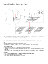
Mounting Options
If there isn’t an existing outlet box, then read
the following instructions. Disconnect the
power by removing fuses or turning off
circuit breakers.
Secure the outlet box directly to the building
structure. Use appropriate fasteners and
building materials. The outlet box and its
support must be able to fully support the
moving weight of the fan (at least 50 lbs.)
Do not use plastic outlet boxes.
Figures 1, 2, and 3 are examples of different
ways to mount the outlet box.
Outlet Box
Note: You may need a longer downrod to
maintain proper blade clearance when install-
ing on a steep, sloped ceiling. The maximum
angle allowable is 30˚. If the canopy touches
downrod, remove the decorative canopy
bottom cover and turn the canopy 180˚ before
attaching the canopy to the mounting plate.
Outlet Box
To hang your fan where there is an existing
xture but no ceiling joist, you may need an
installation hanger bar as shown in Figure 4
(available at your Hampton Bay retailer).
TO REDUCE THE RISK OF FIRE, ELECTRIC
SHOCK OR PERSONAL INJURY, MOUNT TO A
REINFORCED OUTLET BOX CAPABLE OF RELI-
ABLY SUPPORTING 50 LBS MINIMUM (22.7 KGS)
USING THE MOUNTING SCREWS PROVIDED
WITH THE OUTLET BOX. NOTE: MOST OUTLET
BOXES DESIGNED TO SUPPORT LIGHT FIX-
TURES ARE NOT ACEPTABLE FOR SUPPORT-
ING A FAN, AND MAY NEED TO BE REPLACED.
CONSULT A QUALIFIED, LICENSED ELECTRI-
CIAN FOR EXACT SPECIFICATIONS.
Figure 1
Figure 2
Figure 4
Figure 3

non-slotted screws and loosen the slotted
screws. This will enable you to remove the
mounting plate (Figure 6).
4.
Hanging the Fan
REMEMBER to turn off the pow-
er. Follow the steps below to hang your
fan properly.
NOTE: This fan is recommended for the
standard ceiling mounting using the downrod
provided with this fan. When using standard
ceiling installation with the 18 inch downrod
provided, the distance from the ceiling to the
bottom of the fan blades will be approximate-
ly 21.5 inches.
IF YOU FEEL THAT YOU DO NOT
HAVE ENOUGH ELECTRICAL WIRING
KNOWLEDGE OR EXPERIENCE, HAVE
YOUR FAN INSTALLED BY A LICENSED
ELECTRICIAN.
Standard Ceiling Mounting
Remove the canopy ring from the canopy 1.
by turning the ring to the right until it
unlocks (Figure 5).
Remove the mounting plate from the 2.
canopy by loosening the four screws on
the top of the canopy. Remove the two
Remove
Loosen but Do
Not Remove
Figure 5
Figure 6
Route the wires exiting the top of the 3.
fan motor through the decorative motor
collar cover then the canopy ring. Make sure
the slot openings are on top. Route the wires
through the canopy and then through the
ball/downrod assembly (Figure 7).
Loosen, but do not remove, the set 4.
screws on the collar on the top of the
motor housing.
Align the holes at the bottom of the 5.
downrod with the holes in the collar
on top of the motor housing (Figure 7).
Carefully insert the hanger pin through
the holes in the collar and downrod. Be
careful not to jam the hanger pin against
the wiring inside the downrod. Insert the
locking pin through the hole near the
end of the bolt until it snaps into its
locked position, as noted in the circle inset
of Figure 7.
Re-tighten the set screws on the collar on top 6.
of the motor housing.
Make sure the grommet is properly installed 7.
in the collar cover, then slide the collar cover
on the downrod until it rests on the motor
housing. Be sure that the canopy and the col-
lar cover are both oriented correctly.
8. Proceed to “Installing the Fan” section.
FAILURE TO PROPERLY INSTALL SET SCREWS
IN STEP 6 COULD RESULT IN FAN LOOSENING
AND POSSIBLY FALLING.
THE FAN MUST BE MOUNTED WITH A MINIMUM
OF 7 FEET CLEARANCE FROM THE TRAILING
EDGE OF THE BLADES TO THE FLOOR.

5.
Figure 7
Figure 8
Motor Wires
Ball/Downrod
Assembly
Canopy
Canopy
Ring
Cover
Hanger
Pin
Locking
Pin
Motor
Collar
Motor Collar
Tighten
Screws
Pin in
Position
Locked
Reversing
Switch
Installing Fan to
the Outlet Box
WHEN MOUNTING THE FAN ON A SLOPED
CEILING, THE STANDARD BALL/DOWNROD
MOUNTING METHOD MUST BE USED. THE
MOUNTING PLATE MUST BE MOUNTED SO
THAT THE SLOT OPENINGS ARE ON THE
LOWER SIDE BY SLIDING THE MOUNTING
PLATE FROM THE TOP DOWN.
Install the ceiling mounting plate on the out-2.
let box, by sliding the mounting plate over
the two screws provided with the outlet box
(Figure 8). If necessary, use leveling wash-
ers (not included) between the mounting
plate and the outlet box. Note that the at
side of the mounting plate is toward the out-
let box (Figure 8).
Securely tighten the two mounting screws.3.
Carefully lift the fan assembly up to the 4.
ceiling mounting plate. Make sure the tab
on the mounting plate is properly seated in
the groove in the hanger ball.
installed by a licensed electrician.
Follow the steps below to connect the fan
to your household wiring. Use the wire
connecting nuts supplied with your fan
and supplied with remote control. Se-
cure the connectors with electrical tape.
Make sure there are no loose strands or
connections (Figure 9).
Connect both green wires from the down-
1.
rod and mounting plate to the bare copper
(Ground) from the outlet box
Connect the black wire (AC IN L) from
2.
the receiver unit to the black wire from the
outlet box.
Connect the white wire (AC IN N) from
3.
the receiver unit to the white wire from the
outlet box.
Connect the white wire (To Motor N) from
4.
the receiver unit to the white wire from the
fan assembly.
Connect the black wire (To Motor L) from
5.
the receiver unit to the black wire from the
fan assembly.
After wires are connected, carefully tuck them
into the outlet box. Insert the receiver unit into
the mounting plate; make sure the black antenna
wire sits on top of the receiver unit.
Pass the 120-volt supply wires through the 1.
center hole in the ceiling mounting plate as
shown in Figure 8.
Making the Electrical
Connections
REMEMBER to disconnect the power. If
you feel you do not have enough electrical
wiring knowledge or experience, have your fan

6.
Setting the Code
This unit has 16 different code combinations.
To set the code, perform the following steps:
A. Setting the code on the transmitter:
a. Remove the battery cover. Press rmly
below arrow and slide battery cover off.
b. Slide code switches to your choice of up
or down position. (Factory setting is all up).
B. Setting the code on the receiver.
a. Slide code switches to the same position
as set on your transmitter.
b. Replace battery cover on transmitter.
C. Setting the light function on the transmitter.
a. Push the black switch to the left for “No
Dimmer” function.
b. Push the black switch to the right for
“Dimmer” function.
CAUTION:
Ceiling angle shall not exceed 30 degrees.
Controller Model: FAN28R-240W
EACH WIRE NUT (WIRE CONNECTOR) SUP-
PLIED WITH THIS FAN IS DESIGNED TO ACCEPT
UP TO ONE 12 GAUGE HOUSE WIRE AND TWO
WIRES FROM THIS FAN. IF YOU HAVE LARGER
THAN 12 GAUGE HOUSE WIRING OR MORE
THAN ONE HOUSE WIRE TO CONNECT TO THE
FAN WIRING, CONSULT AND ELECTRICIAN FOR
THE PROPER SIZE WIRE NUTS TO USE.
THE FREQUENCIES ON YOUR RECEIVER AND
TRANSMITTER HAVE BEEN PRESET AT THE
FACTORY. BEFORE INSTALLING THE RECEIV-
ER, MAKE SURE THE DIP SWITCHES ON THE
RECEIVER AND TRANSMITTER ARE SET TO
THE SAME FREQUENCY. THE DIP SWITCHES
ON THE TRANSMITTER ARE LOCATED INSIDE
THE BATTERY COMPARTMENT.
Finishing the Fan
Installation
STANDARD CEILING MOUNTING
Align the locking slots of the ceiling canopy 1.
with the two screws in the mounting plate.
Push up to engage the slots and turn clock-
wise to lock in place. Immediately tighten
the two mounting screws rmly.
Install the remaining two mounting 2.
screws into the holes in the canopy and
tighten rmly.
Install the decorative canopy ring by 3.
aligning the ring’s slots with the screws
in the canopy. Rotate the ring counter-
clockwise to lock in place.
You may now proceed to attaching the 4.
fan blades.
WHEN USING THE STANDARD BALL/DOWNROD
MOUNTING, THE TAB IN THE RING AT THE BOT-
TOM OF THE MOUNTING PLATE MUST REST IN
THE GROOVE OF THE HANGER BALL. FAILURE
TO PROPERLY SEAT THE TAB IN THE GROOVE
COULD CAUSE DAMAGE TO WIRING.
Figure 9

7.
Attaching the
Fan Blades
Attach blade to blade arm using decorative 1.
screws and screws as shown in Figure 10.
Start a screw into decorative screws. Repeat
for the two remaining decorative screws and
screws.
Tighten each screw securely.2.
Repeat steps 1 & 2 for the remaining 3.
blades.
Blade
Screws
Blade Arm
Decorative Screws
Figure 10
Figure 11
Blade Balancing
All blades are grouped by weight. Because nat-
ural woods vary in density, the fan may wobble
even though the blades are weight matched.
The following procedure should correct most
fan wobble. Check after each step.
Check that all blade screws are secure.1.
Most fan wobble problems are caused when 2.
blade levels are unequal. Check this level by
selecting a point on the ceiling above the tip
of one of the blades. Measure from a point
on the center of each blade to the point on
the ceiling. Measure this distance as shown
in Figure 11. Rotate the fan until the next
blade is positioned for measurement. Repeat
for each blade. Measurement deviations
should be within 1/8”. Run the fan for 10
minutes.
Use the enclosed Bladed Balancing Kit if 3.
the blade wobble is still noticeable.
TO REDUCE THE RISK OF PERSONAL INJURY,
DO NOT BEND THE BLADE HOLDERS WHILE
INSTALLING, BALANCING THE BLADES, OR
CLEANING THE FAN. DO NOT INSERT FOREIGN
OBJECTS BETWEEN ROTATING BLADES.

8.
Installing the
Switch Box
CAUTION - To reduce the risk of electrical
shock, disconnect the electrical supply circuit to
the fan before installing the switch box.
Remove one serrated head screw from the 1.
black bracket below the fan motor assembly.
Loosen, but do not remove the other two
serrated head screws (Figure 12).
Align the key hole slots in the switch box 2.
adaptor with the two serrated head screws in
the black bracket.
Turn the switch box adaptor clockwise until 3.
the two serrated head screws are situated in
the narrow end of the keyholes.
Re-install the one serrated head screw that 4.
was removed in step 1. Tighten all three ser-
rated head screws rmly.
Remove one serrated head screw from the 5.
switch box adaptor. Loosen but do not re-
move the other two serrated head screws
(Figure 13).
Aligning the “L” shape holes on the switch 6.
box with the serrated head screw on the
switch box adaptor. Turn the switch box to
hold in position.
Install the other serrated head screw that 7.
was removed in step 5. Tighten all 3 serrated
head screws securely.
Serrated Head
Screw(3)
Black
Bracket
Switch Box Adaptor
Switch Box
Switch Box Adaptor
Serrated Head
Screw(3)
Molded
Adaptor
Connector
Figure 12
Figure 13

Operating Your Fan 9.
Remote Control - Your fan is equipped with a
remote control to operate the speed and lights
of your new ceiling fan. For more information
on how to install the remote control, see the re-
mote control instruction along with the remote
control components.
Speed settings for warm or cool weather depend
on factor such as the room size, ceiling height,
number of fans and so on.
The fan shipped from the factory with the re-
versing switch positioned to circulate air down-
ward. If airow is desired in the opposite direc-
tion, turn your fan off and wait for the blades
to stop turning, then slide the reversing switch
(located at the top of the motor housing, refer
to gure 7 on page 5) to opposite position, and
turn fan on again. The fan blades will turn in the
opposite direction and reverse the airow.
Speed1. - The remote features Low, Med, Hi
and Off buttons to select the desired speed
of operation and turn the fan On or Off.
Lights2. - To control the light kit, the remote
features a light/Dimmer button.
Figure 14
Figure 15
Warm weather - (Forward) A downward
air ow creates a cooling effect as shown
in Figure 14. This allows you to set your
air conditioner on a higher setting without
affecting your comfort.
Cool weather - (Reverse) An upward air
ow moves warm air off the ceiling are as
shown in Figure 15. This allows you to set
your heating unit on a lower setting with-
out affecting your comfort.

10. Operating Your Remote Control
Remote Control
Your fan is equipped with a remote control
to operate the speed and lights of your new
ceiling fan. For more information on how
to install the remote control, see the remote
control instruction along with the remote
control components.
Transmitter Operation
NOTE: This remote is equipped with 16 code
combinations. To prevent possible interference
from or to other remote units such as garage
door openers, car alarm or security system,
simply change the combination code but be
sure that the code on both the hand held trans-
mitter and receiver in the fan are matched.
Install a 9 volt battery (not included).
Operating the Fan:
Hi Key - High Speed
Med Key - Medium Speed
Low Key - Low Speed
Off Key - Power Off
Light Key - Light On/Off and Dimmer
(available when an optional light kit is
installed)
Reverse key - Fan Reversing Function
Fan Off Key - Fan Off

Care of Your Fan and Troubleshooting 11.
Care of Your Fan
Here are some suggestions to help you
maintain your fan.
Because of the fan’s natural movement, 1.
some connections may become loose.
Check the support connections, brackets,
and blade attachments twice a year. Make
sure they are secure. (It is not necessary to
remove fan from ceiling.)
Clean your fan periodically to help maintain 2.
its new appearance over the years. Do not
use water when cleaning, this could damage
the motor, or the wood or possibly cause
an electrical shock. Use only a soft brush
or lint-free cloth to avoid scratching the
nish. The plating is sealed with a lacquer
to minimize discoloration or tarnishing.
Warning - Make sure the power is off
before cleaning your fan.
You apply a light coat of furniture polish to 3.
the wood for additional protection and en-
hanced beauty. Cover small scratches with a
light application of shoe polish.
There is no need to oil your fan.4.
The motor has permanently lubricated
sealed ball bearings.
MAKE SURE THE POWER IS OFF AT THE ELECTRICAL PANEL BOX BE-
FORE YOU ATTEMPT TO MAKE ANY REPAIRS. REFER TO THE SECTION,
“MAKING ELECTRICAL CONNECTIONS.”
Fan will not start
Fan sounds noisy
Check main and branch circuit fuses or breakers1.
Check line wire connections to the fan and switch wire connections in 2.
the switch housing. CAUTION: Make sure main power is off.
Check batteries in the transmitter. Does the red LED light come on? Are 3.
you standing close enough to the fan? (Normal range is 10-20 feet.) Are
the dip switch settings the same on the transmitter (hand unit) and re-
ceiver? REMEMBER TO TURN OFF POWER SUPPLY BEFORE
CHECKING THE DIP SWITCH SETTINGS IN RECEIVER.
Make sure all motor housing screws are snug.1.
Make sure the screws that attach the fan blade bracket to the motor hub 2.
are tight.
Make sure wire nut connections are not rattling against each other or 3.
the interior wall of the switch housing.
CAUTION: Make sure power is off.
Allow a 24-hour “breaking in” period. Most noises associated with a 4.
new fan disappear during this time.
If using the Ceiling Fan light kit, make sure the screws securing the 5.
glassware are tight. Check that the light bulb is also secure.
Make sure the canopy is a short distance from the ceiling. 6.
It should not touch the ceiling.
Make sure your outlet box is secure and rubber isolator pads were used 7.
between the mounting bracket and outlet box.
Troubleshooting
Problem Solution

Specications 12.
FAN SIZE SPEED VOLTS
AIRFLOW
CFM
FAN POWER
CONSUMPTION
(WITHOUT
LIGHTS) WATT
AIRFLOW EFFICIENCY
(HIGHER IS BETTER)
CFM/WATT
N.W. G.W. C.F.
68”
Low 120 3780 16 225
33.9
Lbs
37.8
Lbs
3.34Med 120 5453 36 148
High 120 8752 95 91
These are approximate measures. They do not include Amps and Wattage used by the light kit.
Distributed by Home Depot U.S.A., Inc.
2455 Paces Ferry Rd. N.W. Atlanta, Georgia 30339
Vendor Number: 11688

Warranty Information 13.
Hampton Bay Lifetime Limited Warranty
Lifetime Warranty on Motor
Hampton Bay warrants the fan motor to be free from defects in workmanship and material present at
time of shipment from the factory for a lifetime after the date of purchase by the original purchaser.
Hampton Bay also warrants that all other fan parts, excluding any glass or acrylic blades, to be free
from defects in workmanship and material at the time of shipment from the factory for a period
of two years after the date of purchase by the original purchaser. We agree to correct such defects
without charge or at our option replace with a comparable or superior model if the product is re-
turned to Hampton Bay. To obtain warranty service, you must present a copy of the receipt as proof
of purchase. All costs of removing and reinstalling the product are your responsibility. Damage to
any part such as by accident or misuse or improper installation or by afxing any accessories, is not
covered by this warranty. Because of varying climatic conditions, this warranty does not cover any
changes in plated nishes, including rusting, pitting, corroding, tarnishing or peeling. Brass nishes
of this type give their longest useful life when protected from varying weather conditions. A certain
amount of “wobble” is normal and should not be considered a defect. Servicing performed by un-
authorized persons shall render the warranty invalid. There is no other express warranty. Hampton
Bay hereby disclaims any and all warranties, including but not limited to, those of merchantability
and tness for a particular purpose to the extent permitted by law. The duration of any implied war-
ranty which cannot be disclaimed is limited to the time period as specied in the express warranty.
Some states do not allow limitation on how long an implied warranty lasts, so the above limitation
may not apply to you. Hampton Bay shall not be liable for incidental, consequential, or special
damages arising out of or in connection with product use or performance except as may otherwise
be accorded by law. Some states do not allow the exclusion of incidental or consequential damages,
so the above exclusion or limitation may not apply to you. This warranty gives specic legal rights,
and you may also have other rights which vary form state to state. This warranty supersedes all prior
warranties. Shipping costs for any return of product as part of a claim on the warranty must be paid
by the customer.
IMPORTANT NOTE:
To ensure warranty service, if ever
necessary, please register your fan at:
gpwarranty.com
You must present a copy of the original
purchase receipt to obtain warranty service.
G.P. WARRANTY SERVICE CENTER, INC.
WARRANTY SECTION
1951 N.W. 22nd STREET
FORT LAUDERDALE, FLORIDA 33311
Attach receipt here for
easy location.
/