Page is loading ...

Owner's Manual
I PR OFESS IONAL I
i
10 in. Stationary
RADIAL ARM SAW
Model No.
315.220381
Save this manual for
future reference.
CAUTION: Read and follow all
Safety Rules and Operating
Instructions before first use of this
product.
Customer Help Line: 1-800-932-3188
Sears, Roebuck and Co., Hoffman Estates,lL 60179 USA
Visit the Craftsman web page: www.sears.com/craftsman
972000-705
10-99
• Safety
• Features
• Assembly
• Operation
• Maintenance
• Parts List
®

FULL ONE YEAR WARRANTY ON CRAFTSMAN RADIAL ARM SAW
If this CRliFT,_MAN" Radial Arm Saw fails due to a defect in material or workmanshipwithinone year from the
date of purchase, Sears willrepair it, free ofcharge.
Contact a Sears Service Center for repair.
If this productis used for commercial or rentalpurposes, this warranty applies onlyfor 90 days from the date of
purchase.
This warrantygives you specificlegal rights,and you may also have other rightswhichvaryfrom state tostate.
Sears, Roebuck and Co., Dept. 817WA, Hoffman Estates, IL 60179
Your saw has many features for makingcuttingoperations more pleasant and enjoyable. Safety, performance
and dependability have been given top priority in the design of this saw making it easy to maintain and operate.
A CAUTION: Carefully read through this entire owner'smanual before usingyour new saw. Pay close
attention to the Rules For Safe Operation, and all Safety Alert Symbols, includingDanger, Warning and
Caution. If you use yoursaw properlyand onlyfor what it is intended, you willenjoyyears of safe, reliable
service.
_1 Look for this symbol to point out important safety precautions. It means attentionl!! Your safety is
involved.
WARNING:
The operation of any power toolcan result in foreign objects being thrown into your eyes,
which can resultin severe eye damage. Before beginning power tooloperation, alwayswear
safety gogglesor safety glasses withside shieldsand a full face shieldwhen needed. We
recommend Wide Vision Safety Mask for use over eyeglasses or standard safety glasses
withside shields,available at Sears Retail Stores.
• Warranty and Introduction ............................................................................................................................... 2
• Table ofContents.......................................................................................................................................... 2-3
• Rules For Safe Operation............................................................................................................................. 4-7
• Electrical ........................................................................................................................................................ 8-9
• ProductSpecificationsand Glossary ........................................................................................................ 10-1
• Unpackingand Accessories .......................................................................................................................... 11
• Loose Parts List ........................................................................................................................................ 12-14
• Tools Needed ................................................................................................................................................. 15
• Labels........................................................................................................................................................ 16-17
• Features .................................................................................................................................................... 18-21
• Assembly................................................................................................................................................... 22-36
Assembling Leg Stand ................................................................................................................................... 22
MountingSaw to Leg Stand ........................................................................................................................... 23
CRRFI"SHAN'RADIALSAW315.220381 2

AttachingElevating Handwheel ..................................................................................................................... 23
Installingthe Yoke Assembly......................................................................................................................... 24
Removingthe Blade....................................................................................................................................... 25
AttachingTable Supports .............................................................................................................................. 25
Settingthe Arm Lock Knob ............................................................................................................................ 26
Settingthe Yoke Clamp ................................................................................................................................. 26
Settingthe Bevel Lock Lever ......................................................................................................................... 27
Tighteningthe Arm and Column.................................................................................................................... 28
Adjusting the Column Tube ...................................................................................................................... 28-29
Adjustingthe Carriage Bearings.................................................................................................................... 30
Levelingthe Table Supports.......................................................................................................................... 31
Installingthe FrontTable ............................................................................................................................... 32
Levelingthe Front Table ................................................................................................................................ 33
InstallingRear Table, Spacer Table, Fence, and Clamps........................................................................ 33-34
InstallingBlade and Blade Guard .................................................................................................................. 34
AligningRiving Knifeto Blade........................................................................................................................ 35
InstallingRip Scale Indicators ............................................ ,........................................................................... 36
• Adjustments .............................................................................................................................................. 36-42
Aligningthe Arm for Cross Cuts ......................................................................................... :.......................... 37
Aligningthe Blade toTable at 0"Bevel ......................................................................................................... 38
Squaring Blade to Fence ............................................................................................................................... 39
Paralleling Bladeto Table .............................................................................................................................. 40
Aligningthe Rip Scale Indicators................................................................................................................... 41
InstallingControl Cut Device ......................................................................................................................... 42
• Operation .................................................................................................................................................. 43-53
Basic Operation ofthe Radial Arm Saw ........................................................................................................ 43
Types of Cuts ................................................................................................................................................. 43
Switch and Switch Key................................................................................................................................... 44
Causes of Kickback ....................................................................................................................................... 44
AvoidingKickback.......................................................................................................................................... 44
CuttingAids.................................................................................................................................................... 45
Making a Cross Cut ....................................................................................................................................... 46
Making a Miter Cut ......................................................................................................................................... 47
Making a Bevel Cut ........................................................................................................................................ 48
Making a CompoundCross Cut..................................................................................................................... 49
Rip Cut Hazards and Precautions................................................................................................................. 50
Setting Up a Rip Cut ...................................................................................................................... _.......... 50-51
Making a Rip Cut ........................................................................................................................................... 51
Making Other Cuts ......................................................................................................................................... 52
Cutting LongWorkpieces............................................................................................................................... 52
Non-Through Cuts ......................................................................................................................................... 53
• Maintenance .................................................................................................................................................. 54
• Troubleshooting ........................................................................................................................................ 55-59
• Exploded View and Repair Parts Ust ....................................................................................................... 60-81
• Parts Ordering / Service .................................................................................................................... back page
3 i:llnlrrsNnrRADIALSAW315.220381

The purpose of safety symbols Is to attract your attention to possible dangers. The safety symbols, and
the explanations with them, deserve your careful attention and understanding. The safety warnings do
not by themselves eliminate any danger. The instructions or warnings they give are not substitutes for
proper accident prevention measures.
SYMBOL
A
MEANING
SAFETY ALERT SYMBOL
Indicates danger, warningorcaution. May be used in conjunctionwith othersymbolsor
pictographs,
_, DANGER: Failuretoobey a safety warningwillresult in sadous injuryto yourselfor toothers.
Always followthe safety precautionsto reducethe risk offire, electricshock and personalinjury.
WARNING: Failure toobey a safety warningcan resultin seriousinjuryto yourselforto others.
Always followthe safety precautionstoreducethe risk offire, electricshockand personalinjury.
CAUTION: Failuretoobey a safety warningmay resultin propertydamage or personal injuryto
yourself or toothers. Alwaysfollowthe safety precautionsto reducethe riskoffire, electricshock
and personal injury.
Note: Advisesyou of informationor instructionsvitalto the operationor maintenance of theequipment.
IMPORTANT
Servicing requiresextremecare and knowledgeofthe
system and shouldbe performed onlyby a qualified
service technician. For service we suggestyou contact
your nearest Sears repair center. Alwaysuse original
factory replacement parts when servicing.
If you have questionsaboutterms inthe following
rules, refer tothe GlossaryofTerms for Woodworking
or the Featuressection.
_k WARNING: Do not attempt to operate this tool
untilyou have read thoroughlyand understand
completelyall instructions,safety rules, etc.
containedin this manual. Failuretocomplycan
resultin accidents involvingfire, electricshock,
or serious personal injury.Save owner's manual
and review frequently for continuingsafe
operation,and instructingotherswho may use
this tool.
READ ALL INSTRUCTIONS
M KNOW YOUR POWER TOOL. Read the owner's
manual carefully. Learn the saw's applicationsand
limitationsas well as the specificpotentialhazards
related to this tool.
i DO NOT USE IN DANGEROUS ENVIRONMENT.
Do not use power tools near gasolineor other
flammable liquids,in damp or wet locations,or
expose them to rain. Keep the work area well lit.
m KEEP CHILDREN AND VISITORS AWAY. All
visitors shouldwear safety glasses and be kepta
safe distancefrom work area. Do not letvisitors
contactthe toolor extension cordwhile operating.
M KEEP WORK AREA CLEAN. Cluttered work
areas and work benches inviteaccidents. DO NOT
leave toolsor pieces ofwood on the saw while itis
in operation. Keep floorsclean and free of saw-
dust.
n MAINTAIN TOOLS WITH CARE. Keep tools sharp
and clean for better and safer performance. Follow
instructionsfor lubricatingand changing accesso-
ries.
• MAKE WORKSHOP CHILD-PROOF with padlocks
and master switchesor by removingswitch keys.
M USE THE RIGHT TOOL FOR THE JOB. Do not
force the toolor attachment todo a job it was not
designed for.Use itonly the way itwas intended.
B DRESS PROPERLY. Do notwear looseclothing,
gloves, neckties,rings,bracelets, or otherjewelry.
They can get caught and draw you intomoving
parts. Nonslipfootwear is recommended, Also
wear protectivehair coveringto contain long hair.
i ALWAYS WEAR SAFETY GLASSES WITH SIDE
SHIELDS. Everyday eyeglasses have onlyimpact-
resistantlenses; theyare NOT safety glasses.
i NEVER STAND ON TOOL. Serious injurycould
occur ifthe tool istipped or ifthe blade is uninten-
tionallycontacted.
• DO NOT OVERREACH. Keep properfootingand
balance at all times.
i SECURE WORK. Use clamps or a vise to hold
work when practical.It's safer than using your
handand frees bothhands to operate thetool.
[lUI_NaN' RADIALSAW316320381 4

• USE THE PROPER EXTENSION CORD. Make
sure yourextension cordis in good condition,Use
only a cord heavy enough tocarry the currentyour
productwilldraw. An undersizedcord willcause a
drop in line voltage resultingin loss of powerand
overheating. A wire gage size (A.W.G.) of at least
14 is recommended for an extension cord 25 feet
or less in length.If in doubt, use the next heavier
gage. The smaller the gage number, the heavier
the cord,
• AVOID ACCIDENTAL STARTING. Be sure switch
isoff when pluggingin the tool.
• REMOVE WRENCHES AND ADJUSTING KEYS.
Get in the habitof checking - before turningon the
tool- that hex keys and adjustingwrenches are
removed from tool.
• CHECK DAMAGED PARTS. Before usingthe tool
again, check any damaged parts, including guards,
for proper operation and performance. Check
alignment of moving parts, bindingof moving parts,
breakage of parts, saw stability,mounting,and any
other conditionsthat may affect its operation.A
damaged part must be properly repairedor re-
placed by a qualifiedservice technicianat a Sears
repair center to avoid risk of personal injury.
• USE ONLY CORRECT BLADES. Use the right
blade style for the material and the type of cut.
Use only blades marked for at least 5,000 rpmand
10 in. or smaller, with a 5/8 in. arbor hole.
• KEEP GUARDS IN PLACE and in good working
order. This includesthe blade guard, the riving
knife, and the anti-kickbackpawls.
• CHECK DIRECTION OF FEED. When ripping, •
feed work intoa blade or cutter against the direc-
tionof rotationof the blade or cutter.
• NEVER LEAVE TOOL RUNNING UNA'I'rENDED.
TURN THE POWER OFF. Do not leave the tool
until itcomes to a complete stop.
• USE RECOMMENDED ACCESSORIES. Using
improper accessories may risk injury.Consultthe
Accessories sectionfor recommended acceSso-
ries.
• USE ONLY SEARS REPLACEMENT PARTS. All
repairs, whether electricalor mechanical, should
be made by a qualified service technicianat a
Sears repair center.
DISCONNECT ALL TOOLS. When not in use,
before servicing,or when changingattachments,
blades, bits,cutters,etc., all toolsshouldbe
disconnectedfrom the power supply.
• DO NOT FORCE THE TOOL. It willdo the job
better and moresafely at the rate for whichitwas
designed.
• BEFORE MOUNTING, DISCONNECTING OR
REMOUNTING THE MOTOR; unplugthe saw and
remove the switchkey.
_l, WARNING: When servicing,use onlyidentical
Craftsman replacement pads. Use of any other
parts may create a hazard or damage product.
• NEVER USE THIS TOOL IN AN EXPLOSIVE
ATMOSPHERE. Normal sparkingofthe motor
couldignitefumes.
• MAKE SURE THE WORK AREA HAS AMPLE
LIGHTING to see the work and that no obstruc-
tionswillinterferewith safe operation BEFORE
performing any work using thistool.
• DO NOT USE TOOL IF SWITCH DOES NOT
TURN IT ON AND OFF. Have defective switches
replaced by a qualifiedservice technicianat a
Sears repair center.
• GUARD AGAINST ELECTRICAL SHOCK by
preventing bodycontactwith groundedsurfaces
such as pipes, radiators, ranges, refrigerator
enclosures.
• GROUND ALL TOOLS. See Electricalpage.
• WEAR A DUST MASK to keep from inhalingfine
particles.Use wood dustcollectionsystems
whenever possible.
• PROTECT YOUR HEARING. Wear hearing
protectionduring extended periodsof operation.
• DO NOT OPERATE THIS TOOL WHILE UNDER
THE INFLUENCE OF DRUGS, ALCOHOL, OR
ANY MEDICATION.
STAY ALERT AND EXERCISE CONTROL. Watch
what you are doingand usecommon sense. Do
not operate tool when you are tired. Do not
rush.
• AVOID AWKWARD OPERATIONS AND HAND
POSITIONS where a sudden slipcouldcause your
handto move intothe blade, ALWAYS make sure
you have good balance•
5 qlIIFt3NlUr RADIALSAW$15.220_t

• GUARD AGAINST KICKBACK. Kickbackcan
occurwhen the blade stalls, drivingthe work piece
back towardthe operator. It can cause your hand
to contactthe blade, resultingin serious personal
injury. Stay out ofthe blade path and turnswitch
off immediately ifblade binds or stalls.
• DO NOT USE A PERSON AS A SUBSTITUTE
FOR A TABLE if additional support is needed. Use
a support the same height as the table.
• USE A SUPPORT FOR THE SIDES AND BACK
OF THE SAW TABLE when sawingwide or long
workpieces to minimize the risk ofblade pinching
and kickback. Use a sturdy"outrigger"supportto
prevent tipping ifa table extension more than 24
inches long is attached to the saw.
• CUT ONLY WOOD, PLASTIC OR WOOD-LIKE
MATERIALS. Do not cut metal.
• BEFORE MAKING A CUT, be sure all adjustments
are secure.
• NEVER cut more than one piece at a time. DO
NOT STACK more than one workpiece on the saw
table at a time.
• DO NOT REMOVE THE SAW'S BLADE GUARD.
Never operate the saw withthe blade guard
removed. Make sure all guards are operating
properly before each use.
• NEVER PERFORM ANY OPERATION FREE-
HAND. Always place the workpiece to be cut on
the saw table and positionitfirmlyagainstthe
fence as a backstop.
• USE THE RIP FENCE. Always use a fence or
straight edge guide when ripping.
• BE SURE THE BLADE PATH IS FREE OF
NAILS. Inspectfor and remove all nailsfrom
lumber beforecutting.
• BE SURE THE BLADE CLEARS THE WORK-
PIECE. Never startthe saw withthe bladetouching
the stock.
• KEEP HANDS AWAY FROM CUTTING AREA.
Do not reach underneath work or in blade cutting
path with your handsand fingers for any reason.
Always turnthe poweroff when cut is complete.
• USE A PUSHBLOCK OR PUSHSTICK in rip mode
for workpieces so small that yourfingers go under
the blade guard. NEVER TOUCH BLADE or other
moving parts during use, for any reason.
• ALLOW THE MOTOR TO COME UP TO FULL
SPEED before startinga cut to avoidblade binding
or stalling.
ALWAYS PUSH THE WORKPIECE when ripping;
never pull ittowardthe saw.
DO NOT FEED THE MATERIAL TOO QUICKLY.
Do not force the workpiece againstthe blade.
• ALWAYS TURN OFF SAW before disconnecting
it,to avoid accidental startingwhen reconnecting
to the power supply.NEVER leave the saw
unattendedwhileconnected to a power source.
• BEFORE CHANGING THE SETUP, REMOVING
COVERS, GUARDS, OR BLADE; unplugthe saw
and remove the switchkey.
• KEEP TOOL DRY, CLEAN, AND FREE FROM
OIL AND GREASE. Always use a clean cloth
when cleaning. Never usebrake fluids, gasoline,
petroleum-basedproducts,or any solventsto
clean tool.
KEEP BLADES CLEAN, SHARP AND WITH
SUFFICIENT SET. Sharp blades minimizestalling
and kickback.Keep bladesfree of rust,grease,
and pitch.
being turnedoff.
_k WARNING: Bladecoastsafter " =
• USE ONLY OUTDOOR EXTENSION CORDS.
Use onlyextensioncordswith the marking=Ac-
ceptable for use with outdoorappliances;store
indoorswhile not in use."Use extension cordswith
an electricalrating not lessthan the saw's rating.
Always disconnectthe extensioncordfrom the
outletbefore disconnectingthe productfrom the
extensioncord.
INSPECT TOOL CORDS AND EXTENSION
CORDS PERIODICALLY and, if damaged, have
repairedby a qualified servicetechnicianat a
Sears repaircenter. Stay constantlyaware ofcord
locationand keep it well away fromthe moving
blade.
• DO NOT ABUSE CORD. Never yank thecordto
disconnectitfrom receptacle. Keep the cordfrom
heat, oil, and sharp edges.
• SAVE THESE INSTRUCTIONS. Refer to them
frequentlyand use to instructother users. Ifyou
loan someone thistool, loanthem these instruc-
tionsalso.
SAVE THESE INSTRUCTIONS
Clltl_HIIIr RADIALSAW315.220381 6

• SECURE THE SAW. Firmly belt the saw tothe leg •
stand to keep the saw from tipping,walking, or
sliding.
• DO NOT SET UP WORK WITH THE BLADE
SPINNING. Keep the saw power off untilyou are
ready to use it.
• RIP ONLY WORKPIECES LONGER THAN THE
BLADE'S DIAMETER. Never ripa piece ofwood
that is shorterthan the diameter ofthe blade.
• NEVER LOWER AN UNLOCKED REVOLVING
CUTTING TOOL. Always lockthe carriage lock
knob beforelowering the blade.
• SHUT OFF THE POWER TO FREE A JAMMED
GUARD. Press the switchoff before puttingyour
hands near the blade. Wait forthe bladeto stop,
then free the guard.
• LOCK THE SAW BEFORE MOVING IT. Secure
the radial arm with the arm lock knob. Secure the
carriage with the carriage lock knob.
• POSITION THE WORKPIECE WITH THE FIN-
ISHED SIDE DOWN. Ifthe anti-kickback pawls
catch the woodto stopkickback, theycould mar
the top surface or cause splintering.
• POSlI_ION THE WORKPIECE SO NO ONE MUST
STAND IN LINE WITH THE BLADE. if kickbackor
climboccurs, a helper, operator, or observer in the
sawblade path could be seriouslyinjured.
• POSITION THE CUT SO THE WASTE PART
FALLS OFF. Never use a length stop on the free
end ofthe workpiece. Never applyforce tothe free
end or hold itwhile the sawblade is rotating.
_i, WARNING: In a ripcut, holdingthecut-off edge
behindthe blade can cause the cutedges to
pinch,riskingkickback, tt couldcause the blade
to climbover the front edge ofthe woodand
contact your hand.
• BEFORE STARTING EACH CUT, check that no
play exists inthe carriage. Be sure the arm, yoke
and bevel locks and clamps are tight. Verify the
blade, all handles,blade washers, and blade nuts
are secure.
• BEFORE MAKING A CUT, test the upper and
lower blade guards for free movement up and
down. Positionthe nose ofthe guard tojust clear
the workpiece.
• AVOID KICKBACK AND POSSIBLE INJURY by
preventing heeling, grabbing, and pinching.
BEFORE CUTTING, position and tighten the blade
guard and anti-kickbackpawls.Test the pawls to
make sure they would stop kickbackifit started.
Keep the pointssharp.
KEEP THE SAW BLADE PATH CLEAR. Position
the saw to allowenough room on all sides so
neitherthe operator nora visitorstands in line with
the sawblade.
• AVOID HEELING by adjustingthe saw blade so it
exactly parallelsthe fence during rippingopera-
tions.
• AVOID GRABBING in ripmode by keepingthe
saw blade correctlyadjusted and by feeding the
work from the infeed side (oppositethe anti-
kickbackpawls).
• AVOID PINCHING by usinga rivingknife and
sharpsaw blade. Keep the work positionedfirmly
againstthe fence.
• USE IN-RIP WHENEVER POSSIBLE byposition-
ingthe work sothe blade is between (inside)the
columnand the motor.
'NEVER ADJUST GUARD, PAWLS, OR BLADE
WITHOUT DISCONNECTING THE POWER.
Always turn offthe switchand unplugthe cord
before freeing a jammed blade, tighteninga loose
blade, or repositioningthe guard or pawls.
_k CAUTION: Do not turnthe motorswitch on and
offrapidly. Thiscan loosen the sawblade.
NEVER CUT MORE THAN ONE PIECE OF
WOOD AT A TIME. The feed will be uneven and
could cause the blade to pick up one or more
pieces and cause seriousinjury.
TURN OFF SAW IF A STRANGE NOISE OR
HEAVY VIBRATION OCCURS. Immediately turn
offthe saw, locate the source, and correctthe
problembeforeusing the saw further.
POSITION THE CUT SO THE BLADE WILL NOT
EXTEND BEYOND THE EDGE OF THE TABLE.
KEEP THE GUARDS IN PLACE AND THE WORK
SURFACE CLEAR DURING A CUT. Small objects
or wood sliverscan ricochetfrom the blade intothe
fence and backtoward the operator. Ifthe blade
loosens slivers, remove them with a stick,not your
hand.
IN A RIP CUT, DO NOT LET GO OF THE WORK-
PIECE UNTIL THE CUT IS COMPLETE. When the
workpiece isfed intothe blade, pushthe workplace
all the way past the blade.
7 CRIIFI"SNIIN'RADIALSAW315.220381

EXTENSION CORDS
Use only 3-wire extension cords that have 3-prong
groundingplugs and 3-pole receptacles that accept
the tool's plug. When using a power tool at a consider-
able distance from the power source, use an exten-
sioncord heavy enough to carry the current that the
tool willdraw. An undersized extension cord will
cause a drop in line voltage, resulting in a loss of
power and causing the motor to overheat. Use the
chart provided below to determine the minimum wire
size required in an extension cord. Only round jack-
eted cords listed by Underwriter's Laboratories (UL)
should be used.
Length of Extension Cord Wire Size (A.W.G.)
Up to 25 feet 14
26-100 feet 12
When workingwith the tooloutdoors,use an exten-
sioncord that is designed for outsideuse. This is
indicatedbythe letters WA on the cord'sjacket.
Before usingan extension cord, inspectitfor looseor
exposed wires and cut or worn insulation.
_k CAUTION: Keep the cordaway from the cutting
area and position the cordso that itwill not be
caughton lumber, tools, or other objectsduring
cuttingoperations.
ELECTRICAL CONNECTION
Your Sears Craftsman Radial Arm Saw ispowered by
a precisionbuiltelectric motor. It shouldbe connected
toa power supply that is 120 volta, 60 Hz, AC only
(normal household current). Itshould be connected
toa 240 volt power supply only if it has been reset
according to the Instructions inthis manual. The
motorhas been set at the factory for 120 volts; ifit is
reconnectedto operate at 240 volts,the main power
cord plugand any receptacle mustbe replaced with
devices rated for 240 volts. This toolwillnot operate
on direct current (DC). A substantialvoltage drop will
cause a lossof power and the motorwilloverheat. If
the saw does not operate when plugged intoan outlet,
double checkthe power supply.
SPEED AND WIRING
The no-load speed of yoursaw is approximately 3,600
rpm. This speed is notconstant. For voltage, the
wiring in a shop isas importantas the motor's horse-
power rating. A line intendedonlyfor lightscannot
properlycarry a power toolmotor. Wire that isheavy
enough for a shortdistance willbe too lightfor a
greater distance. A linethat can supportone power
tool may not be able to supporttwo or three tools.
GROUNDINGINSTRUCTIONS
In the event of a malfunctionor breakdown, grounding
providesa path ofleast resistance for electriccurrent
to reduce the risk ofelectricshock. Thistool is
equippedwith an electric cordhaving an equipment-
groundingconductorand a groundingplug.The plug
mustbe plugged intoa matching outletthat isprepedy
installedand groundedin accordance withall local
codes and ordinances.
Do not modify the plug provided. If itwillnot fit the
outlet, have the properoutlet installedbya qualified
electrician. Improperconnectionof the equipment-
groundingconductorcan resultin a riskofelectric
shock.The conductorwith insulationhaving an outer
surfacethat isgreen with or withoutyellowstripesis
the equipment-groundingconductor.Ifrepair or
replacement ofthe electriccordor plugis necessary,
do not connectthe equipment-groundingconductorto
a live terminal.
Check with a qualified electricianor service personnel
ifthe groundinginstructionsare notcompletely
understood,or ifin doubt as to whether the toolis
propedygrounded.
Repair or replace a damaged or worncord immedi-
ately.
This toolis intendedfor use on a circuitthat has an
outlet likethe one shownin Figure 1.It also hasa
groundingpinlike the one shown.
GROUNDING
PIN
COVEROFGROUNDED
OUTLETBOX
Fig. 1
rRIIFTSNIIrRADIALSAW316.220381 8

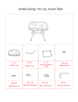
CHANGING VOLTAGE
See Figures2-4.
Your radial saw has been set up at the factoryto
operate efficientlyon a 120V AC single voltagecircuit.
However, if heavy duty operation is required,the
circuits are overloaded, or the circuitis lowvoltage,
have a qualified electricianchange the voltageon the
main power system to a 240V AC voltagecircuit.
,_ WARNING: The controlcut device is set up for
a 120V AC single voltage circuit.Do not modify
the control cut cord. Identify the controlcut
cordand tie it back out of the way.
• Correctly identifythe controlcut cord, unplugit,
and set itaside.
• Unplug the main power cord.
• Remove the blade followingthe procedure in the
Assembly section.
• Remove the pan head screw above the blade
arbor on the motorcover. Liftmotorcover to
expose switch. See Figure2.
• Use a small screwdriverto slide the dual voltage
switch tothe 240V position.See Figures 3 and 4.
• Reinstall motorcover.
• Replace the 120V plugon the main cordwith a UL
listed 240V, 15 amp, 3-prong plug.
• Follow the instructionsprovidedwith the UL listed
plug.
• Plug the cord intoa 240V, 15 amp, 3-blade recep-
tacle. Make sure the receptacle isconnectedto a
240V AC power supplythrougha 240V branch
circuitthat has a 15 amp fuse or circuitbreaker.
Note: No adapter isavailable for this type of plugor
receptacle.
MOTORCOVER
PANHEADSCREW
LIFTMOTORCOVERTOEXPOSESWITCH
SLIDEASSHOWNFORSINGLEVOLTAGECIRCUITS
SWITCHSHOWNIN110-120VOLTPOSmON
Fig. 3
UFTMOTORCOVERTOEXPOSESWITCH
SLIDEASSHOWNFORDUALVOLTAGECIRCUITS
SWITCHSHOWNIN220-240VOLTPosmoN
Fig. 4
O
BLADEARBOR Fig. 2
9 (RIIR'SHnN"RADIALSAW315.220381

BladeArbor 518in.
BladeDiameter 10in.
BladeBevelAngle 0°- 90°
Radial Arm Swing Range 45" minimumleft - 90" right
Blade Height Adjust 5.35 in.
Carriage Travel 17.25 in.
CuttingCapacity - Maximum CrossCut 15.50 in.
CuttingCapacity - Maximum Out-Rip 26 in.
Cutting Capacity - Maximum In-Rip
Depth of Cut at 90"
Depth of Cut at 45"
Table Size
Table Height
Rating
Input
No Load Speed
16 in.
3in.
2.25 in.
40 x 27.75 x 1 in.
36 in.
120V/240V 60 Hz -AC only
13.0/6.5 Amperes
3,600 RPM
Bevel Cut
A cut made across a workpiece with the blade at any
angle otherthan 90" tothe table surface.
Chamfer
A cut removinga wedge from a block sothe end (or
part of it) isangled ratherthan at 90 degrees.
Climb
A hazard in whichthe blade "climbs" over and out of
the workpiece,pullingthe stockout of the operator's
hands or runningacross the workpiece.
Compound Cut
A cross cut with both a miter angleand a bevel angle.
Cross Cut
A cutting operationwith the blade parallelto the
carriage arm and the blade teeth pointingdown. It can
be across or with the grain, normallyacross the grain
or width ofthe workpiece.
Dado Cut
A non-throughcut that leaves a square notchor
trough;requires a special blade.
Featherboard
A device to help guide workpieces during ripcuts•
Fence
A piece of wood used as a edge guide for the
workpiece. Located perpendicularto the carriage arm.
Can be placed at different distancesfrom the rear
table edge in combinationwith the othertable pieces
and is secured with table clamps•
Freehand
Dangerous practice of makinga cut withoutusinga
fence.
Gum
A sticky,sap-based residue from wood products.
Heel
Alignment ofthe blade to the fence.
Infeed
The side ofthe blade where the bladeteeth pointup,
oppositethe anti-kickback pawls.
In-Rip
Atype ofripcut in whichthe blade isbetween the
columnand the motor.
Kerr
The space left by the removalof material in a cut or
the slotproduced bythe blade in a non-throughcut.
Kickback
A hazard that can occurwhen blade binds or stalls,
throwing workpiece back towardoperator.
Leading End
The end of the workpiece pushed intothe cuttingtool
first.
Miter Cut
A verticalcut made at any angle otherthan 0"across
the workpiece.
Molding
A shapingcut that gives a varied shape to the
workpiece and requiresa special blade.
Out-Rip
A type of ripcut in whichthe motoris between the
blade and the column• (The blade is "outside" the
motor).
Puahatick
A device used to feed the workpiece throughthe saw
blade duringcutting operations.It helps keep the
operator'shandswell away from the blade.
Rabbet
A type of cutthat gives a notch inthe edge of a
workpiece.
Resaw
A cuttingoperation to reducethe thickness of the
workpiece to make thinnerpieces,
[IIRR3MIIIr RADIALSAW31S_220381 10

Resin
A sticky, sap-based substance.
Rip Cut
In a radial saw, a cut made with the blade parallelto
the fence and perpendicular tothe arm. Can be
across or with the grain.The teeth point up at the
point ofcontact with the wood.
Sawblade Path
The area directly in linewith the blade -- over, under,
behind, or in frontof it. Also, the workpiece area which
will be or has been cut bythe blade.
Set
The distancethat the tip ofthe saw bladetooth is off
set from the face of the blade.
Throw-Back
Saw throwingback a workpiece similarto kickback.
Through Sawing
Any cuttingoperation where the blade extends
completelythroughthe workpiece.
Trailing End
The workpiece end lastcut bythe blade in a ripcut.
Workpiece
The item on whichthe cuttingoperation is being done.
The surfaces ofa workpiece are commonly referredto
as faces, ends, and edges.
Worktable
The surface on whichthe workpiece rests while
performinga cuttingoperation.
_i, WARNING: To prevent accidental startingthat
could cause possible serious personalinjury,
assemble all parts to yoursaw before connecting
itto power supply. The saw shouldnever be
connected to the power supply when you are
assembling parts, makingadjustments, installing
or removingblades, or when not in use.
_lb WARNING: If any parts are missing,do not
operate this tool untilthe missing parts are
replaced. Failure todo so could resultin possible
serious personal injury.
• Carefully remove all partsfrom the cartonand
placethe saw on a level work surface. Separate
and checkagainstthe listof looseparts.
• Do not discardthe packingmaterials untilyou have
carefully inspectedthe saw, identifiedall parts, and
satisfactorilyoperated your new saw.
Note: If any parts are damaged or missing,do not
attempt toplug in the power cord and turnthe
switchon untilthe damaged or missingparts
are obtainedand are installedcorrectly.
The following recommendedaccessoriesare currentlyavailableat Sears RetailStores.
• Steel and carbide tipped circularsaw blades • Adjustabletaper jig
• Hold down clamps • Sawdust collectorshroud
• Saw baskets
_lb WARNING: The use ofattachments or accessoriesnot listedmightbe hazardous.
11 [RAFTSNAN'RADIALSAW315,220381

Check all loose parts from the box with the list below. Use the instructionson the followingpages to assemble.
All fasteners are shown actual size.
1. Saw Assembly.................................................... 1
SAWASSEMBLYSHOWNASPACKED
2.
Elevating Handwheel .
A. Handwheel .......... :.......... _..........:.................... 1
B. Screw (10-24 x 5/8 in. Soc. Hd.).................... 1
C. Star Washer ................................................... 1
C
[lUlFTSMIIM'RADIALSAW315.220381
Fig. 5
3. Blade Wrench ..................................................... 2
12
4. Hex Key
A. 3/16 in.Hex Key............................................. 1
B. 1/4 in. Hex Key............................................... 1
Fig. 6A

Checkall looseparts from the box with the list below. Use the instructionson the followingpages to assemble.
Allfasteners are shown actual size.
5.
Saw Base To Leg Stand Assembly
A. Saw Assembly (notshown) ........................... 1
B. Leg Stand Assembly (not shown).................. 1
C. Hex bolt (5/16-18 x 518in. Hex Head) ........... 4
D. Washer (5/16 in.) ........................................... 8
E. Lock washer (5/16 in.) ................................... 4
F. Hex Nut (6/16-18) ........................................... 4
C D E F
9. Fence.................................................................. 1
6. Hardware for Front Table
A. Fronttable .................................................... ,. 1
B, Screw (1/4-20 x 1 in.)..................................... 4
C. Washer (1/4 in.) ............................................. 4
D. Lock washer (1/4 in.) ..................................... 4
E. Hex nut (1/4-20) ............................................. 4
11. Scale Indicator
B C D E
7. Rear Table ........................................................... 1
8. Spacer Table ...................................................... 1
10. LevelingHardware for FrontTable
A. Screw (1/4-20 x 1-3/4 in.) .............................. 1
B. Washer ........................................................... 1
C, U-clip.............................................................. 1
D. Setscrew ........................................................ t
E. Tee nut........................................................... 1
A B
D E
A. Screw ............................................................. 4
B. Speed Nut ...................................................... 2
C. Indicator ......................................................... 2
D. Switch Key ..................................................... 2
IIoII
C
Fig. 6B
13 CHR2NH"RADIALSAW316,220381

Check all loose partsfrom the box withthe list below. Use the instructions on thefollowing pages to assemble.
All fasteners are shown actual size.
12. Table Support
A. Table Support Rails ....................................... 2
B. Square,head bolt (5/16-18 x 3/4 in.) .............. 4
C. Flat washer (5/16 in.) ..................................... 4
D. Lock washer (5/16 in.) ................................... 4
E. Hex nut (5/16-18) .................... ....................... 4
A
15.
Leg Stand ........................................................... 1
A. Leg ................................................................. 4
B. Long bottom brace ......................................... 2
C, Long top brace ............................................... 2
D. Short bottom brace ........................................ 2
E. Short top brace .............................................. 2
F. Foot ................................................................ 4
G. Screw (1/4-20 x 5/8 in.) ............................... 40
H. Star washer .................................................. 40
I. Hex nut (1/4-20) ............................................ 40
J. Hex nut (3/8-16) .............................................. 8
14. Owner's Manual (not shown) ............................. 1
F
m
G
000
H I J
Fig. 6C
CRIIFT,_NAIrRADIALSAW315.220381 14

The following toolsare needed for assemblyand alignment. They are not includedwith this saw.
io@C
HEXKEYS:
5/32in.ANDI/8 in.
LEVEL
MEDIUMFLATBLADESCREWDRIVER
#2PHILLIPSSCREWDRIVER
PENCIL
SMALLHAMMER
PLIERS
WRENC S 7/161n,1/21n,9/161n_15/161n
FRAMINGSQUARE
Fig. 7
t5 rEAFTSMRIrRADIALSAW315.220381

A
A
(I 10 inch Radii Arm Saw
I 3,_RPM 120/?._ImVOLT_1316.SAJnp60Hz ACONLYI
I WHEN_RVlCING,USEOl'€.yI_NTICALC_ |
I RE_.A_NTPARTS. _ r
I MOOEL 315.22_181 SER,NO /_1_ i I
D
c
i
A WARNING/ ADVERTENCIA
ill
• For your own safety, Read and understand
owner's manual before operating saw.
* This tool has more than one connection to the
power soorce.
. To reduce the risk of electrical shock or injury,
disconnect al| power connections
•When servicing, use only identical
replacement parts.
• Par,, su seguddad, lea y entlenda el manual del
propieterio antes de oparer la sierra,
lilll I_
,I
Fig. 8A
£HfTg411r RAI_L SAW$IS_20_ 16

G
G
_WARNING
ADVERTENCIA
• Read and understand owners manual
before operating saw.
• For your safety, do not use
accessories without proper guarding.
• Provide proper workpiece support
• Position cutting tool behind the
fence.
• With power off and switch key
removed, turn cutting tool by hand to
make sure it does not strike guard,
fence or any other saw parts.
• Pars su saguridad, lea y entienda el
manual del propietario antes de
operar la sierra.
On I
OffO
./" A WARNING
;_,,_,.. ADVERTENCIA
F_ _[yo, ra.duty,readownersremrelbeloreqereUng
jv
jr • Wearsofely goggles.
_r • DOnotperformfreehandcuts.
jr • Returncarriagetofull roarpositionaftereachcrosscut.
jr • See thutnmtisnsonhowto reducetheriskofkickback,
jr • Whenripping,usepushsUchwhenbladeisset2 Inchesormorefrom
/ then.
j_ • Whenripping,usepuchbthckandauxiliaryfencewhenbladeis oslbetween
1/2and2 Inchesfromfelwe. Denutreakedp cutsosrmwarthsa1/2tnch.
• KeephandsOutof pathof blade.
• no notreacharoundsawblade.
• TurnpowerOftandwaifforbladeto stepbeforereevingwarkplose or
changing|eRinos.
• Unplugsawbeforechangingthe bladeorservicing,
• Parssuseguridad,lea yentlendeelmanualdelpreplutarloantesdeopersrla sierra
H
LOCKED
UNLOCKED
, Fig, 8B
17 rltllFI3NIIlr RADIALSAW315.220381

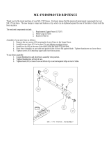
KNOWYOURRADIALSAW
See Figure 9A.
OVERVIEW - The main operatingcomponents include
the column,the arm, and the yoke assembly (yoke,
motor, and blade), and their operationis summarized
in the paragraph below. Safety features and control
functionsare givenalso. Spending a few minutes
reviewingthe illustrationsand features listbelow and
on the followingpages to locate these items willmake
assembly easier.
METHOD OF OPERATION: The column at the back
ofthe saw supportsthe radial arm. The arm can be
raisedor lowered to change the blade height or
swiveled left and rightfor a mitercut. A yoke fitsinto
a carriage on the arm, whichcan travel backand
forward. The yoke supportsthe yokeassembly
(motor, blade, and blade guard) and can be pivoted
sothe blade faces right,front, or left. The motorcan
be rotated tochange the blade angle.
Control functions include1) column height(elevating
handwheel), 2) arm angle (arm lock knob), 3) yoke
movement on arm (*carriage lockknob) 4) yoke
rotation(*yoke pivotlatch and *yoke lock handle),and
5) blade bevel (*bevel index lever and *bevel lock
knob).
Safety features includethe controlcutdevice, the
removable switchkey, and the blade guard assembly.
Never operate the saw withoutensuringthese safety
features are in place and functioning correctly.
On a radial saw, "cross cut"means a cutparallelto
the arm, and a "rip cut"is perpendiculartothe arm.
There are several ways to make cuts, dependingon
the size and materialof the workpieceand the end
resultdesired.
Beforeattemptingto use yoursaw, familiarize yourself
with all operatingfeatures and safety requirementsof
your Sears Craftsman Radial Arm Saw.
*Shown on following pages
ARMLOCKKNOB
YOKE
CARRIAGE
ANDCOVER
CONTROL
CUTHOUSING
SWITCHANDKEY
BLADEAND
BLADEGUARD
COLUMN
MOTOR
ELEVA_NG
HANDWHEEL
Fig. gA
cRnFt3MIIrRADIALSAW315.220381 18

FEATURESLIST
See Figures9A-9D.
ADJUSTABLE TABLES - A_narrow spacer table and
wider rear table that can be repositionedoreven
replaced with different tables. See Figure 9C.
ANTI-KICKBACK PAWLS - Toothed pawls thatsnag
the work in case of kickbackduring ripcuts. (When
the blade is parallelto the arm, the pawls are in front
ofthe blade.) Keep the pawls in place to reduce risk
ofinjury. See Figure 9D.
ARM - The assembly extendingfrom the column,
whichsupportstheyoke, the motor,and the blade.
See Figure 9A.
ARM LOCK KNOB - Controls arm angle. Use to set
the arm tothe positivestops at 0°, 45" left, and 45"
rightand tolock the arm in place. Located on top of
arm at front. See Figures9A and 9B.
BEVEL INDEX KNOB - Controls the blade angle
between positivestopsat 0°, 45", and 90°. Located
behindthe handle. See Figure 9B.
BEVEL INDEX SCALE - Shows the blade angle for
bevel cutsand is located behindthe handle. See
Figure 9B.
BEVEL LOCK LEVER - Sets and locksblade angle. It
is locatedbelow the handle. See Figure9B.
BLADE - For maximum performance, use the Crafts-
man 40-tooth, 10 in. carbide-tipped blade provided
with yoursaw. It isa high-qualitycombinationblade
suitablefor rippingand crosscutoperations.Blades
recommendedfor other operationsare listedin the
Accessorysectionofthis manual. The blade is
powered by the main motorand turned off bythe
switch.See Figure 9D.
,_ WARNING: Use only blades rated for at least
5,000 rpm and recommendedfor use onthis
saw. Check with your nearest Sears retailstore.
BLADE GUARD ASSEMBLY - Protectiveunitover
the blade, with a rivingknife,anti-kickback pawls,an
upper blade guard, a lowerouter blade guard, and a
lowerinner blade guard. Always keep each item in
place unless specificallyinstructedto move it. See
Figures 9A and 9D.
BLADE GUARD CLAMP SCREW - Secures the
bladeguard to the motor. Locatedbetween the blade
andthe motor. See Figure 9D.
MITERSCALE
ARMLOCKKNOB
YOKE
YOKEPIVOTLATCH
RIP
SCALE(S)
COLUMNTUBE
BEVEL
INDEXKNOB
YOKE
LOCKHANDLE
INDEXSCALE
ER
MOTOR
19
COLUMNSUPPORT
Fig. gB
(IIRFTSMRN"RADIALSAW315.220381

CARRIAGE-Slidesalongtrackunderarmand
supportsyoke.Containedintwocarriagecovers,one
oneachsideofthearm.See Figure9C.
CARRIAGE LOCK KNOB - Controlswhether the
cardage islocked or can travel. Locatedon the left
side ofthe arm on the carriage cover. See Figure 9C.
COLUMN - Upright housingat the beck ofthe saw,
consistingofa column supportand a columntube.
The column tube can be raisedor lowered withthe
elevating handwheel at the front ofthe saw. See
Figures 9A and 9B.
CONTROL CUT DEVICE - Limitscarriage speed to
preventclimb, usinga cable from thecarriage to the
column. Has a separate motoron leftside, which is
activated by the switchtrigger inthe handle. The
cable returnsthe carriage tothe columnwhen the
motoris not activated. Speed is adjusted with a
thumbwheelon the handle. It runson a separate
120V AC single voltage circuit.See Figure 9C.
_1, WARNING: When connectingonlyone ofthe
cords, squeeze the switchtrigger inthe handle.If
the main motorcord alone isconnected,the
switchtrigger inthe handle will notoperate the
controlout device. The carriage cannot be
advancedwithout powertothe controlcutdevice.
DUAL VOLTAGE - If needed, your main power
sourcemay be rewired by a qualified electricianto
providea 240V AC circuit.See the Electricalsection.
DUST GUIDE - Directssawdust, created from the cut
being made, in the directionyou set. Locatedat the
rear ofthe upper blade guard. See Figure 9D.
ELEVATING HANDWI-IEEL - The handwbeel below
the worktable (in front) thatchanges the height ofthe
arm and the blade. See Figure9C.
FENCE - Removable guide for work, whichextends
acrosswidthof table. See Figure 9C.
FRONT TABLE - Fixed portionofthe worktable that
supportsthe work. See Figure 9C.
HANDLE - Used to pullthe yoke assembly. Mounted
on the yoke to the rightofthe blade. See Figure 9C.
HOLD DOWN - A metal guard tocontrolworkpiece
climbduring rip cuts.When blade parallelsarm, hold
down isover the backof the blade. See Figure 9D.
HOLD DOWN KNOB - Controls placement ofthe hold
down and locks it in place. See Figure 9D.
MITER SCALE - Shows the miter angle settingofthe
arm. See Figure 9B.
TRACK CARR_GE CARRIAGE
LOCKKNOB ANDCOVER
CONTROL
CUTMOTOR
CUTCABLE
REAR
TABLE
SPACER
TABLE
SWITCH
ANDKEY
CONTROLCUT
THUMBWHEEL
FRONTTABLE
ELEVATING
HANDWHEEL
Fig. 9C
[RFT|NnlrRADIALSAW315.220381 20
/