Makita 6203DWAE User manual

Category
Power drills
Type
User manual

Makita 6203DWAE is a cordless driver drill equipped with an electric brake and a fast charger. It has a no-load speed of 0-400 RPM and can drill holes in steel up to 10 mm and in wood up to 25 mm. The drill also includes a built-in LED light for illuminating dark work areas and a keyless chuck for easy bit changes.

Makita 6203DWAE is a cordless driver drill equipped with an electric brake and a fast charger. It has a no-load speed of 0-400 RPM and can drill holes in steel up to 10 mm and in wood up to 25 mm. The drill also includes a built-in LED light for illuminating dark work areas and a keyless chuck for easy bit changes.

Y
Cordless Driver Drill
Capacities
Steel
Wood
Wood
screw Machine screw
____
10
mm
25
mm
,
6.4 mm
x
76
mm
,llm
1,,4,,1
1318'7
11")
1114"
x
3")
Equipped with Electric
Brake
MODEL
6203DWAE
Dimensions Net
(L
x
W
x
HI
No load speed
1RPMI
weight
,,200
~
4oo
233
mm
x
77
mm
x
241
mm
1.7 kg
(3
8
lbsl
High Low
19-118''
x
3"
x
9~1/2")
With Fast Charger
Battery Cartridge
9122
Voltage
96V
INSTRUCTION MANUAL
Model DC1410 Fast Charger
Input
Output Charging time
__
A
C
onlv
50
H2
60
H2
DC
72V
~
14.4V
1
Hr
S
PEC
I
FI CAT1
0
N
S
Model
6203DA
*
Manufacturer reserves the right
to
change specifications without notice.
*
Note: Specifications may differ from country
to
country.
WARNING: For your personal safety, READ and UNDERSTAND before using
SAVE THESE INSTRUCTIONS FOR FUTURE REFERENCE.
GENERAL SAFETY RULES
(For
All
Battery
Operated
Tools)
WARNING! Read and understand
all
instructions.
Failure
to follow all instructions listed below, may result
in
electric
shock, fire and/or serious personal injury.
SAVE THESE
INSTRUCTIONS
Work Area
*Keep your work area clean and well
lit.
Cluttered benches and dark areas invite
accidents.
Do
not operate power tools in explosive atmospheres, such as in the presence
of flammable liquids, gases, or dust. Power tools create sparks which may ignite
the dust or fumes.
Keep bystanders, children, and visitors away while operating a power tool.
Distractions can cause
you
to loose control.
Electrical Safety
Do
not abuse the cord. Never use the cord to carry the tool. Keep cord away
from heat, oil, sharp edges, or moving parts. Replace damaged cords immedi-
ately. Damaged cords may create a fire.
A
battery operated tool with integral batteries or a separate battery pack must
be recharged only with the specified charger for the battery.
A
charger that
may be suitable for one type of battery may create a risk of fire when used with
another battery.
Use battery operated tool only with specifically designated battery pack. Use
of any other batteries may create a risk of fire.
Personal Safety
*Stay alert, watch what you are doing, and use common sense when operating
a power tool.
Do
not use tool while tired or under the influence of drugs, alcohol,
or medication.
A
moment of inattention while operating power tools may result
in
serious personal injury.
Dress properly. Do not wear loose clothing or jewelry. Contain long hair. Keep
your hair, clothing, and gloves away from moving parts. Loose clothes, jewelry,
or long hair can be caught
in
moving parts.
*Avoid accidental starting. Be sure switch is
in
the locked or off position before
inserting battery pack. Carrying tools with your finger on
the
switch or inserting
the battery pack into a tool
with
the switch on invites accidents.
Remove adjusting keys or switches before turning the tool on.
A
wrench or
a key that is left attached to a rotating part of the tool may result
in
personal injury.
Do not overreach. Keep proper footing and balance at all times. Proper footing
and balance enable better control of the tool in unexpected situations.
Use safety equipment. Always wear eye protection. Dust mask, non-skid safety
shoes, hard hat, or hearing protection must be used for appropriate conditions.
Tool
Use and Care
Use clamps or other practical way to secure and support the workpiece to a
stable platform. Holding the work by hand or against your body is unstable and
may lead to
loss
of control.
Do not force tool. Use the correct tool for your application. The correct tool
will do the job better and safer at the rate for which
it
is designed.
*Do not use tool if switch does not turn
it
on or off. A tool that cannot be
controlled
with
the switch is dangerous and must be repaired.
Disconnect battery pack from tool or place the switch
in
the locked or off
position before making any adjustments, changing accessories, or storing the
tool. Such preventive safety measures reduce the risk of starting the tool
acc id en
t
a
I
I
y.
Store idle tools out of reach of children and other untrained persons.
Tools
are
dangerous in the hands of untrained users.
When battery pack is not
in
use, keep
it
away from other metal objects like:
paper clips, coins, keys, nails, screws, or other small metal objects that can
make a connection from one terminal to another. Shorting the battery terminals
together may cause sparks, burns, or a fire.
Maintain tools
with
care. Keep cutting tools sharp and clean. Properly maintained
tools
with
sharp cutting edge are less likely to bind and are easier to control.
Check for misalignment or binding of moving parts, breakage of parts, and any
other condition that may affect the tool’s operation. If damaged, have the tool
serviced before using. Many accidents are caused by poorly maintained tools.
Use only accessories that are recommended by the manufacturer for your
model. Accessories that may be suitable for one tool may create a risk of injury
when used on another tool.
Service
*Tool service must be performed only by qualified repair personnel. Service or
maintenance performed by unqualified personnel may result
in
a risk of injury.
When servicing a tool, use only identical replacement parts. Follow instructions
in
the Maintenance section of this manual.
Use
of unauthorized parts or failure
to
follow Maintenance Instructions may create a risk of shock
of
injury.
3
Specific Safety Rules
1.
Hold tool by insulated gripping surfaces when performing an operation where
the cutting tool may contact hidden wiring. Contact
with
a "live" wire
will
also make exposed metal parts
of
the tool "live" and shock the operator.
2.
Be aware that this tool is always
in
an operating condition, because
it
does
not have to be plugged into an electrical outlet.
3.
Always be sure you have a firm footing.
Be sure no one is below when using the tool
in
high
locations.
4.
Hold the
tool
firmly.
5.
Keep hands away from rotating parts.
6.
Do
not leave the tool running. Operate the tool only when hand-held.
7.
Do
not touch the drill bit or the workpiece immediately after operation; they
may be extremely hot and could burn your skin.
4
SYMBOLS
The followings show the symbols
used
for tool.
?.J
n
A
Ab
.../
min
...........
volts
.................................
amperes
.................................
hens
.................................
seconds
.................................
alternating current
.................................
direct current
.................................
no load speed
.................................
alternating or direct current
.................................
Class
II
Construction
.................................
splash-proof construction
.................................
watertight construction
................................
revolutions or reciprocation per minute
@
.................................
number of blow
5
IMPORTANT SAFETY INSTRUCTIONS
FOR CHARGER
&
BATTERY CARTRIDGE
I.
SAVE THESE INSTRUCTIONS
-
This manual
Length of Cord (Feet)
25
AWG Size of Cord
18
50
100
150
18
18
16
6
ADDITIONAL SAFETY RULES
FOR CHARGER
&
BATTERY CARTRIDGE
1.
Do not charge Battery Cartridge when temperature
is
BELOW
10°C
(5OOF)
2.
Do not attempt to use a step-up transformer, an engine generator or DC power
3.
Do
not allow anything to cover or clog the charger vents.
4.
Always cover the battery terminals
with
the battery cover when the battery
5.
A battery short can cause a large current flow, overheating, possible burns
or ABOVE 4OoC (104OF).
receptacle.
cartridge is not used.
and even a breakdown.
(1)
Do not touch the terminals
with
any conductive material.
(2)
Avoid storing battery cartridge
in
a container with other metal objects such
(3)
Do not expose battery cartridge to water or rain.
ture may reach or exceed
5OoC
(122OF).
completely worn out. The battery cartridge can explode
in
a fire.
as nails, coins, etc.
6.
Do not store the tool and Battery Cartridge
in
locations where the tempera-
7.
Do not incinerate the Battery Cartridge even if
it
is severely damaged or is
SAVE THESE INSTRUCTIONS.
7
Installing
or
removing battery cartridge
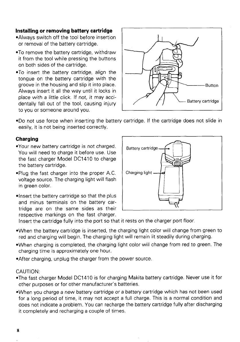
*Always switch off the tool before insertion
or removal of the battery cartridge.
*To remove the battery cartridge, withdraw
it from the tool while pressing the buttons
on both sides of the cartridge.
*To
insert the battery cartridge, align the
tongue on the battery cartridge with the
groove in the housing and slip it into place.
Always insert it all the way until it locks in
place with a little click. If not, it may acci-
dentally fall out of the tool, causing injury
to you or someone around you.
Button
Battery cartridge
*Do
not use force when inserting the battery cartridge.
If
the cartridge does not slide in
easily, it is not being inserted correctly
Charging
*Your new battery cartridge is not charged.
You will need to charge it before use. Use
the fast charger Model DC1410 to charge
the battery cartridge.
*Plug the fast charger into the proper A.C.
voltage source. The charging light will flash
in green color.
*Insert the battery cartridge
so
that the plus
and minus terminals on the battery car-
tridge are on the same sides as their
respective markings on the fast charger.
Insert the cartridge fully into the port
so
that it rests on the charger port floor.
red and charging will begin. The charging light will remain lit steadily during charging.
charging time is approximately one hour.
*When the battery cartridge is inserted, the charging light color will change from green to
*When charging
is
completed, the charging light color will change from red to green. The
*After charging, unplug the charger from the power source.
CAUTION:
*The fast charger Model DC1410 is for charging Makita battery cartridge. Never use it for
other purposes or for other manufacturer’s batteries.
*When you charge a new battery cartridge or a battery cartridge which has not been used
for
a
long period of time, it may not accept
a
full charge. This is
a
normal condition and
does not indicate a problem. You can recharge the battery cartridge fully after discharging
it completely and recharging
a
couple of times.
8
*If you charge
a
battery cartridge from
a
just-operated tool or
a
battery cartridge which has
been left in
a
location exposed to direct sunlight or heat for
a
long time, the charging light
may flash in red color. If this occurs, wait for
a
while. Charging will begin after the battery
cartridge cools. The battery cartridge will cool faster if you remove the battery cartridge
from the fast charger.
*If the charging light flashes alternately in green and red color
a
problem exists and charg-
ing is not possible. The terminals on the charger or battery cartridge
are
clogged with
dust
or
the battery cartridge
is
worn
out
or
damaged.
*If you wish to charge two battery cartridge, allow 15 mimutes between charging on the
fast charger.
ASSEMBLY
Installing or removing driver bit or drill bit
CAUTl
ON
:
Always be sure that the tool is switched off and the battery cartridge is removed before
installing or removing the bit
Hold the ring and turn the sleeve counter-
clockwise to open the chuck jaws. Place
the bit in the chuck as far as it will go. Hold
the ring firmly and turn the sleeve clock-
wise
to
tighten the chuck.
To remove the bit, hold the ring and turn
the sleeve counterclockwise.
When not using the driver bit, keep it in the
bit holders. Bits 45 mm (1-3/4") long can be
kept there.
Tighten
Slee
Ring
:ve
-
Bit
-
I
Bit holder
2
9
OPERATION
Switch action
CAUTION:
Before inserting the battery cartridge into the tool, always check to see that the switch
trigger actuates properly and returns to the
"OFF"
position when released
To
start the tool, simply pull the trigger.
Tool
speed is increased by increasing pres-
sure on the trigger. Release the trigger to
stop.
77-
Switch trigger
Reversing switch action
CAUTIO N:
*Always check the direction of rotation before operation
*Use the reversing switch only after the tool comes to
a
complete stop. Changing the
direction of rotation before the tool stops may damage the
tool
This
tool
has
a
reversing switch to change
the direction of rotation. Depress the
reversing switch lever from the A side for
clockwise rotation
or
from the
B
side for
counterclockwise rotation. When the switch
lever is in the neutral position, the switch
trigger cannot be pulled.
Speed change
To
change the speed, first switch off the
tool and then slide the speed change lever
to the
"11"
side
for
high speed or
"1"
side
for low speed. Be sure that the speed
change lever is set to the correct position
before operation. Use the right speed for
your
job.
Reversing switch lever
-
Clockwise Counterclockwise
Low speed
0
High speed
a
Speed change
lever
10
CAUTION:
*Always set the speed change lever fully to the correct position.
If
you operate the tool
with the speed change lever positioned half-way between the
"I"
side and
"11"
side, the
tool may be damaged.
*Do
not use the speed change lever while the tool is running. The tool may be damaged.
Adjusting the fastening torque
The fastening torque can be adjusted in
18
steps by turning the adjusting ring
so
that
its graduations are aligned with the pointer
on the tool body. The fastening torque is
minimum when the number
1
is aligned
with the pointer, and maximum when the
8
marking
is
aligned with the pointer.
The clutch will slip
at
various torque levels
when set at the number
1
to
5.
The clutch
is designed not to slip at the
8
marking.
Before actual operation, drive
a
trial screw
into your material or
a
piece
of
duplicate
material to determine which torque level is required for
a
particular application.
NOTE:
*The adjusting ring does not lock when the pointer is positioned only half-way between
*Do
not operate the tool with the adjusting ring set between the number
5
and the
8
the graduations.
marking. The
tool
may be damaged.
Screwdriving operation
Place the point
of
the driver bit in the
screw head and apply pressure to the tool.
Start the tool
slowly
and then increase the
speed gradually. Release the trigger as
soon as the clutch cuts in.
11
NOTE:
*Make sure that the driver bit is inserted straight in the screw head, or the screw and/or
bit may be damaged.
Nominal diameter
of
wood screw
lmm)
*When driving wood screws, predrill pilot
holes to make driving easier and to pre-
vent splitting of the workpiece. See the
chart.
Recommended size
of
pilot
hole
Imm)
3
5
19/64")
3.8 15/32")
I
2 2
-
2
5
13/32"
-
3/32")
1
2
5
-
2.8 (3132''
-
7/64',)
*If
the tool is operated continuously until the battery cartridge has discharged, allow the
tool to rest for
15
minutes before proceeding with
a
fresh battery.
Drilling operation
First, turn the adjusting ring
so
that the pointer
on
the tool body points to the
fi
marking.
Then proceed as follows.
*Drilling in wood
When drilling in wood, best results are obtained with wood drills equipped with a guide
screw. The guide screw makes drilling easier by pulling the bit into the workpiece.
To prevent the bit from slipping when starting a hole, make an indentation with
a
center-
punch and hammer at the point to be drilled. Place the point of the bit in the indentation
and start drilling.
Use a cutting lubricant when drilling metals. The exceptions are iron and brass which
should be drilled dry.
*Drilling in metal
CAUTION:
*Pressing excessively on the tool will not speed up the drilling. In fact, this excessive pres-
sure will only serve to damage the tip of your bit, decrease the tool performance and
shorten the service life of the tool.
*There is
a
tremendous force exerted on the tool/bit
at
the time of hole breakthrough. Hold
the tool firmly and exert care when the bit begins to break through the workpiece.
*A
stuck bit can be removed simply by setting the reversing switch to reverse rotation in
order to back out. However, the tool may back out abruptly
if
you do not hold
it
firmly.
*Always secure small workpieces in
a
vise or similar holddown device.
*If the tool is operated continuously until the battery cartridge has discharged, allow the
tool to rest for
15
minutes before proceeding with a fresh battery.
12
ACCESSORIES
784206-5
784207-3
CAUTION:
These accessories or attachments are recommended for use with your Makita tool specified
in
this
manual. The use of any other accessories
or
attachments might present a risk of injury to persons.
The accessories
or
attachments should
be
used only
in
the proper and intended manner.
Bits Drill bits
Tested best in Makita driver-drills for smooth fast drill-
ing and more holes per battery change. High speed
steel. For drilling in metal, wood and plastic. Jobbers
length. Special surface treatment for lubricity gives
smoother drilling.
Size Part
No.
Phillips
No.
2 711000-A-A
6
pc.
set: 1/16", 118". 3/16", 114".
5/16", 318'' Best selling bits in
110 (4-3/8")
150 (5-7/8") convenient
case.
-
Square drill bit 784606-0A
711011-A 1/16" 1/16"
-
71 1012-A 3/32" 3/32"
Part No. Size
L
(mm)
784203-1 65 (2-5/8")
Flute
length
718"
1-114"
1-518"
2"
2-5/16"
2-1 12"
2-314"
2-5/16"
3-311
6"
3-7/16"
3-518''
Overall
length
1-718''
2-1 14"
2-314"
3-118"
3-1 12"
3-314"
4/"
4- 114"
4- 112"
4-314"
5"
Rubber pad assembly
Wool
bonnet Battery cover
Part
No.
123001-2 Part
No.
743401-6 Part
No.
414938-7
Foam polishing pad
Part
No.
743023-2
Fast charger
Model
DC1410
Part
No.
1131 50-3
@
C'
Double-ended Phillips
I
Battery cartridge
91
22
Slotted bit
Part
No.
192596-6
1-3/4" long
Part
No.
784637-8
Plastic carrying case
14
July-O9-'96
US
CORDLESS DRIVER DRILL
Model
6203DWA
Note: The switch and other part configurations
may differ from country
to
country.
15
MODEL 6203DWA
';,'OM
:&,
DESCRIPTION
14
15
16
17
18
19
20
21
22
23
24
25
26
July-19-'96
US
';;M
$FD
DESCRIPTION
1
1
1
1
1
1
1
1
4
3
2
2
1
10
11
12
13
Name
Plate
Tapping
Screw
Bind
PT
3x16
Bit
Holder
Housing Set IWith Item
211
Change
Lever
Compression Spring
4
Compression Spring
4
FIR
Change
Lever
Switch
Holder
Spring Terminal
I
+
1
Spring Terminal
I
~
I
Pan Head
Screw
M3x8
11
29
32
41
51
61
71
81
91
1
1
1
1
DC Motor
GEAR ASSEMBLY
Sleeve
10
Keyless Drill Chuck
10
Hex. Socket Head
Bolt
M5x21
Leaf
Spring
Makita Label
Housing
Set
lWilh
Item
41
Pan
Head
Screw
M3x12
Tapping
Screw
ST
4x8
Brush Holder Cap
Carbon Brush
High Capacity Battery
9122
Note:
The
switch
and
other
part
specifications may
differ
from
country to country.
16
Recycling the Battery
The
only
way to dispose
of
a Makita battery is
to recycle it. The law prohibits any other
method
of
disposal.
I
Ni-Cd
To recycle the battery:
1.
Remove the battery from the tool.
2.
a). Take the battery to your nearest Makita Factory Service Center
or
b). Take the battery to your nearest Makita Authorized Service Center or
Distributor that has been designated
as
a Makita battery recycling location.
0
Call your nearest Makita Service Center or Distributor
to
determine the location
that provides Makita battery recycling. See your local Yellow Pages under
”Tools-Electric’
MAKITA
LIMITED
ONE YEAR WARRANTY
Warranty Policy
Every Makita
tool
is thoroughly inspected and tested before leaving the factory.
It
is warranted
to
be free of defects from workmanship and materials for
the
period of ONE YEAR from the date of
original purchase. Should any trouble develop during this one-year period, return the COMPLETE
tool,
freight prepaid,
to
one of Makita’s Factory or Authorized Service Centers. If inspection shows
the trouble
is
caused
by
defective workmanship or material, Makita
will
repair (or at our option,
replace) without charge.
This Warranty does not apply where:
repairs have been made or attempted
by
others:
0
repairs are required because of normal wear and tear:
e
The
tool
has
been abused, misused or improperly maintained;
0
alterations have been made
to
the
tool.
IN NO EVENT SHALL MAKITA BE LIABLE FOR ANY INDIRECT, INCIDENTAL OR CON-
SEQUENTIAL DAMAGES FROM THE SALE OR USE OF THE PRODUCT. THIS DISCLAIMER
APPLIES BOTH DURING AND AFTER THE TERM OF THIS WARRANTY.
MAKITA DISCLAIMS LIABILITY FOR ANY IMPLIED WARRANTIES, INCLUDING IMPLIED
WARRANTIES OF “MERCHANTABILITY” AND “FITNESS FOR A SPECIFIC PURPOSE,”
AFTER THE ONE-YEAR TERM OF THIS WARRANTY.
This Warranty gives
you
specific legal rights, and you may also have other rights which vary from
state
to
state.
Some
states do not allow the exclusion or limitation of incidental or consequential
damages,
so
the above limitation or exclusion may not apply
to
you. Some states do not allow
limitation on how long an implied warranty lasts,
so
the
above limitation may not apply
to
you.
i
Makita Corporation
of
America
2650 Gainesville Hwy., Buford, GA
30518
884077
-
063
PRINTED
IN
USA
  • Page 1 1
  • Page 2 2
  • Page 3 3
  • Page 4 4
  • Page 5 5
  • Page 6 6
  • Page 7 7
  • Page 8 8
  • Page 9 9
  • Page 10 10
  • Page 11 11
  • Page 12 12
  • Page 13 13
  • Page 14 14
  • Page 15 15
  • Page 16 16
  • Page 17 17

Makita 6203DWAE User manual

Category
Power drills
Type
User manual

Makita 6203DWAE is a cordless driver drill equipped with an electric brake and a fast charger. It has a no-load speed of 0-400 RPM and can drill holes in steel up to 10 mm and in wood up to 25 mm. The drill also includes a built-in LED light for illuminating dark work areas and a keyless chuck for easy bit changes.

Ask a question and I''ll find the answer in the document

Finding information in a document is now easier with AI