McQuay MCC010M User manual

Category
Split-system air conditioners
Type
User manual
Models: MWSC 010 B/BR MWSC 025 B/BR
MWSC 015 B/BR MWSC 030 B/BR
MWSC 020 B/BR MWSC 050 B/BR
CMWSC -2006
Split Water Source Heat Pump
And Cooling Only Unit
Page 1
Features ......................................................................................................................................2
Specifi cations .............................................................................................................................4
Outlines And Dimensions ..........................................................................................................7
Electrical Connection And Parameter ....................................................................................15
Installation Of Indoor Unit .......................................................................................................25
Installation Of Outdoor Unit ....................................................................................................36
Vacuuming And Charging Method ..........................................................................................42
Overall Checking ......................................................................................................................44
Remote Control Operation Guide ...........................................................................................45
Standard Operation Conditions ..............................................................................................47
Start-up ......................................................................................................................................47
Servicing And Maintenance .....................................................................................................48
Cleaning & Flushing System ...................................................................................................50
Troubleshooting .......................................................................................................................51
Contents
Note: Installation and maintenance are to be performed only by qualifi ed personnel who are
familiar with local codes and regulations, and experienced with this type of equipment.
Caution: Sharp edges and coil surfaces are a potential injury hazard. Avoid contact with them.
Warning: Moving machinery and electrical power hazard. May cause severe personal injury or death.
Disconnect and lock off power before servicing equipment.
McQuay” is a registered trademark of McQuay International. All rights reserved throughout the world.
© 2003 McQuay International
“Bulletin illustration cover the general appearance of McQuay International products at the time of publication and
we reserve the right to make change in design and construction at any time without notice”
Page 2
Features
Save Energy
This decentralized, year-round heating and cooling system consists of a two-pipe closed loop water circuit, through
which non-refrigerated water circulates continuously throughout the building. Locating the piping within the building
negates the need of for piping insulation. These systems achieve energy conservation by pumping heat from warm
to cold spaces whenever they coexist anywhere within the building. On demand for heating a space, the conditioner
will absorb heat from the loop circuit, whereas on demand for cooling a space, the conditioner will reject heat to the
loop circuit. The system provides the essential benefi t of decentralized and individual choice of heating or cooling.
The occupant may select heating or cooling or shut off the conditioner, serving an individual space without affecting
conditioners operated in other spaces. The occupant may realize this freely at any time of the day or year.
Flexible Investment
The period of the project installing is short and the original cost of investment is low. It is convenient to install
according to occupant demand.
Convenient Control
Each room can be controlled individually without affecting the other space.
High Effi ciency
The unit is operated in high effi ciency and saves running cost due to water as cooling and heating media.
Running Quiet
The unit is designed into split confi guration which is a thorough solution to the noise problem. The indoor unit can be
installed wherever is suitable. The outdoor unit can be placed on outside of the wall or the ceiling, at the balcony or
aisle. It is an ideal device for home, industrial or commercial place due to its low noise.
Elegant, Neat And Tidy
While the rest of the unit is concealed, the wall or ceiling air grilles is exposed. This design concept has in mind: (a)
aesthetic beauty (b) optimum space utilization. It is ideal for offi ce, hotel, hospital and restaurants application.
Easy And Flexible Installation
The physical height of the unit is only 224 mm, and only a clearance of 75 mm between any beam and the false
ceiling is required. It is therefore offering greatest fl exibility in selecting installation location.
ROOM LAYOUT 1 ROOM LAYOUT 2 ROOM LAYOUT 3
ADAPTOR
Page 3
Microcomputer remote control
The microcomputer remote control has following functions
Five optional operation modes (heat/cool/dry/fan/auto).
Fan speed can be set at high, medium, low and automatic.
Sleep mode automatically increase set temperature since temperature is lower at night thus achieving healthy
sleep.
Microcomputer controlled thermostat precisely controls room temperature resulting in energy saving and increases
comfort.
Hot start and hot keep mode do not supply air for 30 sec. After deicing as well as initial operation of heating mode.
This prevents cold draft and maintains the indoor comfort.
Timer on/off can be preset for the maximum of 15 hours.
Easy maintenance
This simple design concept has a friendly maintenance and servicing in mind. Access to all the internal parts of the
unit can be from either side panels or the top panel of the unit by loosening a few screws.
Page 4
Model
Indoor unit
MCC010M MCC010MR MCC015M MCC015MR MCC020M MCC020MR MCC025M MCC025MR MCC030M MCC030MR MCC050M MCC050MR
Outdoor unit
MWSC010B MWSC010BR MWSC015B MWSC015BR MWSC020B MWSC020BR MWSC025B MWSC025BR MWSC030B MWSC030BR MWSC050B MWSC050BR
Rated cooling capacity W
2700 4200 5600 6900 8200 12300
Rated heating capacity W
--- 3000 --- 4300 --- 5600 --- 7800 --- 10500 --- 15000
Air fl ow m³/h
550 760 1150 1400 1700 2040
Power source V/Ph/Hz
220V~/50Hz 380V/3N~/50Hz
Indoor Unit
External static
pressure
Pa
0, 15, 30, 50 15, 30, 50, 70
Dimension
length x wide x high
mm
830x566x224 930x566x224 1290x560x250 1290x560x250 1640x560x250 1900x560x250
Weight kg
25 30 36 36 48 59
Sound level dB(A)
38 38 42 49 43 46
Outdoor Unit
Compressor model
ROTARY SCROLL
Condenser
Type
TUBE IN TUBE BPHE
Water
ow
m³/h
0.56 0.8 1.1 1.3 1.6 2.5
Water
pressure
drop
kPa
7.8 11 16.6 14 12 20
Piping
size
in
Rc1/2 Rc3/4 G3/4
Dimension
length x wide x high
mm
736x411x437 802x421x548 839x498x545
Weight kg
51 52 56 57 62 63 63 64 74 75 84 85
Sound level dB(A)
34 37 41 41 41 42
Rated
power
Cooling W
740 740 1170 1170 1635 1635 1800 1950 2350 2350 3140 3460
Heating W
--- 725 --- 1100 --- 1470 --- 1840 --- 2360 --- 3500
Rated
current
Cooling A
3.5 5.5 7.5 7.6 8.3 9.0 11.1 10.8 5.7 7.0
Heating A
--- 3.4 --- 5.2 --- 6.8 --- 8.6 --- 10.8 --- 7.3
Refrigerant
R22
Charge kg
0.6 0.65 0.8 0.85 1.0 1.15 0.85 1.05 2.4 2.4 2.95 3.15
Piping size
Liquid pipe Φmm(in)
6.35(1/4") 6.35(1/4") 6.35(1/4") 9.52(3/8") 9.52(3/8") 9.52(3/8")
Gas pipe Φmm(in)
9.52(3/8") 12.7(1/2") 15.88(5/8") 15.88(5/8") 15.88(5/8") 19.05(3/4")
Ceiling Concealed Heat Pump Models
Note: 1 specifi cation will be subjected to change by manufacturer without prior notice.
2 cooling capacity is based on 26.7
°C(DB),19.4°C(WB) entering air temperature and 29.4°C entering water
temperature,35
°C leaving water temperature.
3 heating capacity is based on 21.1
°C(DB),15.6°C(WB) entering air temperature and 21.1°C entering water
temperature.
Specifi cations
Page 5
Ceiling Exposed Heat Pump Models
Model
Indoor Unit MCM020D MCM020DR MCM030D MCM030DR MCM050D MCM050DR
Outdoor Unit MWSC020B MWSC020BR MWSC030B MWSC030BR MWSC050B MWSC050BR
Cooling Capacity(W) 5250 5250 8200 8200 12300 12300
Heating Capactiy(W) -5600-10500 - 14500
Power Source 220V~/50Hz 380V/3N~/50Hz
Power Input( W)
Cooling 1495 1495 2350 2350 3060 3060
Heating - 1480 - 2360 - 3500
Rated Current(A)
Cooling 7.3 7.3 11.1 10.8 5.7 7.0
Heating -6.8-10.8-7.3
Sound Level dB(A)
Indoor unit 48 48 50 50 52 52
Outdoor unit 41 41 41 41 42 42
Refrigerant R22
Charge (kg) 1.0 1.0 2.8 2.98 3.4 3.4
Weight (kg)
Indoor Unit 39 39 44 44 64 64
Outdoor Unit 62 63 91 92 84 85
Piping Size (mm)
Liquid pipe 6.35 9.52 9.52
Gas pipe 15.88 15.88 19.05
Note: 1 specifi cation will be subjected to change by manufacturer without prior notice.
2 cooling capacity is based on 26.7
°C(DB),19.4°C(WB) entering air temperature and 29.4°C entering water
temperature,35
°C leaving water temperature.
3 heating capacity is based on 21.1
°C(DB),15.6°C(WB) entering air temperature and 21.1°C entering water
temperature.
Page 6
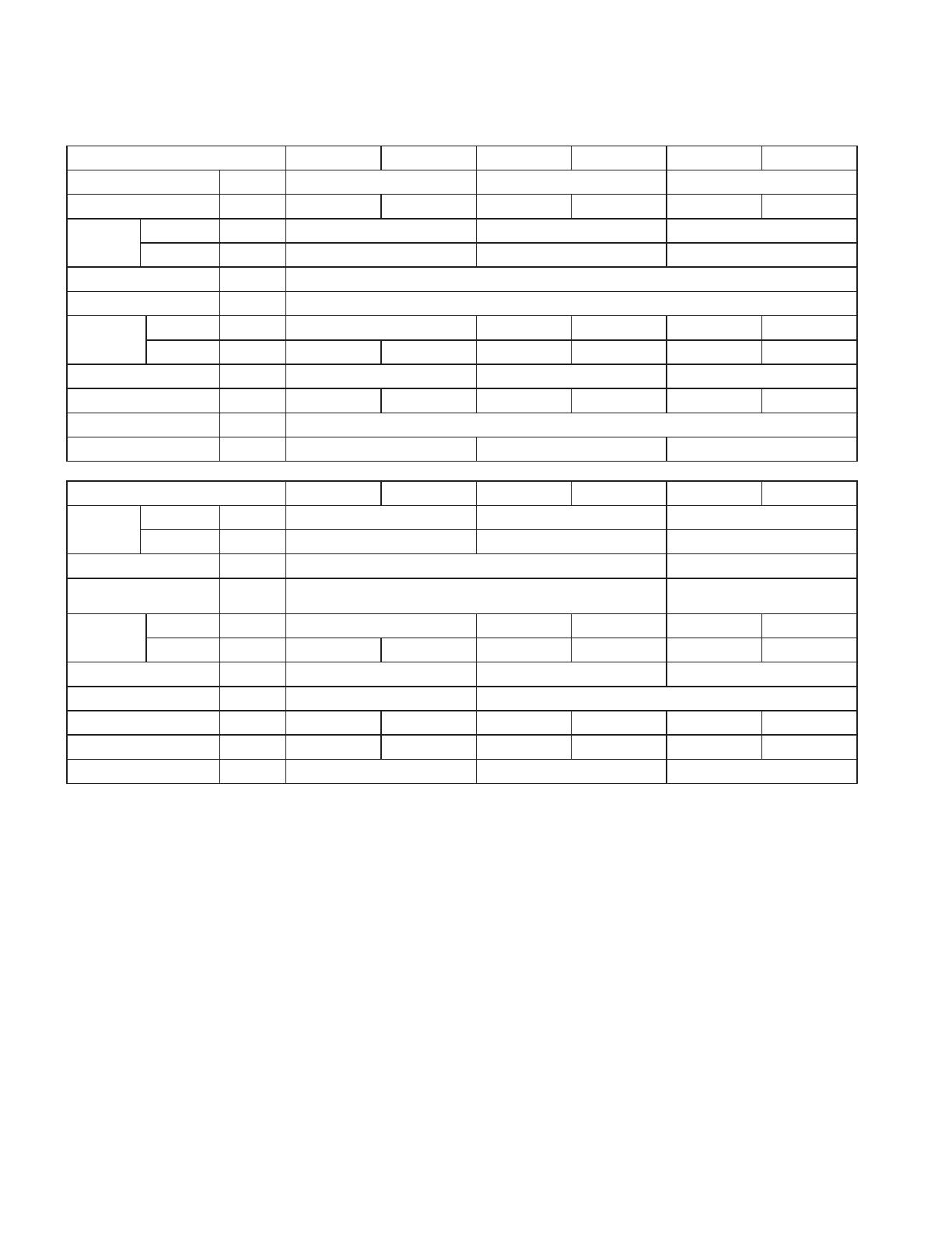
Ceiling Cassette Heat Pump Models
Indoor Unit MCK 020A MCK 020AR MCK 030A MCK 030AR MCK 050A MCK 050AR
Cooling Capacity W 5,600 8,200 12,300
Heating Capacity W —5,600—10,500 14,500
Piping Size
Liquid Pipe Φmm(in) 6.35 (1/4") 9.52 (3/8") 9.52 (3/8")
Gas Pipe Φmm(in) 15.88 (5/8") 15.88 (5/8") 19.05 (3/4")
Refrigerant R22
Power Source 220V~/50Hz
Power Input
Cooling W 1,400 2,370 2,370 3,060 3,060
Heating W 1,480 2,490 3,290
Air Flow m³/h 1,100 1,300 1,850
Weight(Indoor Unit) kg 37.5 37.5 39.5 39.5 39.5 39.5
ESP Pa 0
Sound Level dB(A) 41 45 49
Outdoor Unit MWSC 020B MWSC 020BR MWSC 030B MWSC 030BR MWSC 050B MWSC 050BR
Piping Size
Liquid Pipe Φmm(in) 6.35 (1/4") 9.52 (3/8") 9.52 (3/8")
Gas Pipe Φmm(in) 15.88 (5/8") 15.88 (5/8") 19.05 (3/4")
Power Source 220V~/50Hz 380V/3N~/50Hz
Protection Device Pressure Protector
Overload. Phase and Pressure
Protector
Rated
Current
Cooling A 6.5 11.4 11.4 5.6 7.0
Heating A —7.1—12.1— 7.3
Water Flow m
3
/h 1.15 1.5 2.37
Water Pipe Size in Rc1/2 Rc3/4
Weight(Outdoor Unit) kg 62 63 91 92 84 85
Charge(R22) kg 1.1 1.13 2.85 2.8 3.3 2.8
Sound Level dB(A) 41 41 42
Note: 1 specifi cation will be subjected to change by manufacturer without prior notice.
2 cooling capacity is based on 26.7
°C(DB),19.4°C(WB) entering air temperature and 29.4°C entering water
temperature,35
°C leaving water temperature.
3 heating capacity is based on 21.1
°C(DB),15.6°C(WB) entering air temperature and 21.1°C entering water
temperature.
Page 7
Indoor unit model: MCC 010M /MCC 010MR
Indoor unit model: MCC 015M / MCC 015MR
unit: mm
712
830
900
930
484
524
566
22
224
162
40
224
180
4-10x20
unit: mm
22 40
566
612
830
800
730
484
524
224
162
224
180
4-10x20
Outlines and Dimensions
Page 8
Indoor unit model: MCC 020M / MCC 020MR
MCC 025M / MCC 025MR
Indoor unit model: MCC 030M /MCC 030MR
118
R3/4
270
187
560
965
262
258
250
948
978
1290
560
280 13
208
6-10x16
118
560
280 13
208
187
R3/4
560
1315 258
262
1298
1337
1640
250
270
6-10x16
unit: mm
unit: mm
Page 9
Page 10
75
Water pipe outlet Rc1/2
4- 17
329
698
437
637
411
381
91
170
83
93
145
736
Liquid pipe
Gas pipe
Water pipe inlet Rc1/2
89
87
75
73
4- 17
Water pipe outlet Rc1/2
Water pipe inlet Rc1/2
437
736
698
637
411
381
329
180
167
Liquid pipe
Gas pipe
Outdoor unit model: MWSC 015B/MWSC 015BR
Outdoor unit model: MWSC 020B/MWSC 020BR
unit: mm
unit: mm
Model
Piping size(mm)
Liquid Gas
MWSC025B/BR φ6.35 φ12.7
Model
Piping size(mm)
Liquid Gas
MWSC025B/BR φ9.52 φ15.88
Page 11
84
64
75
Water pipe outlet Rc1/2
4- 17
Water pipe inlet Rc1/2
637
698
736
437
381
411
329
92
250
Liquid pipe
Gas pipe
126
83
108
Gas pipe
Water pipe inlet Rc3/4
Liquid pipe
Water pipe outlet Rc3/4
4- 17
339
391
421
696
759
548
73 165
250
64
802
Outdoor unit model: MWSC 025B/MWSC 025BR
Model
Piping size(mm)
Liquid Gas
MWSC025B/BR φ9.52 φ15.88
unit: mm
unit: mm
Outdoor unit model: MWSC 030B/MWSC 030BR
Model
Piping size(mm)
Liquid Gas
MWSC030B/BR φ9.52 φ15.88
Page 12
15686
77
Power line inlet port
Liquid pipe
Gas pipe
Water pipe inlet G3/4
Water pipe outlet G3/4
545
839
723
783
498
408
468
250
115
64
4- 17
Outdoor unit model:MWSC 050B/MWSC 050BR
Model
Piping size(mm)
Liquid Gas
MWSC050B/BR φ9.52 φ19.05
Page 13
PULL PULL PULL PULL
A
C
L
G
J
K
D
B
I
M
F E
PULL PULL PULL PULL
A
C
L
G
J
H
K
D
B
I
H
M
F E
Model : MCM 020 / 030 / 050 D
MCM 020 / 030 / 050 DR
MODEL MCM 020D/DR MCM 030D/DR MCM 050D/DR
A 1174 1174 1674
B 75 75 75
C 1082 1082 1582
D 68 68 68
E 58 93 93
F 156 156 156
G 1214 1214 1714
H 57 57 57
I 670 670 670
J 216 216 216
K 319 319 319
L 879 879 1379
M 517 517 517
Page 14
Model : MCK 020 / 030 / 050 A
MCK 020 / 030 / 050 AR
M
Note : Dimension in mm
K
L
C
A
I
H
J
E
F
B
D
G
Model A B C D E F G H I J K L M
MCK020A/AR 820 875 548 820 363 335 28 930 930 642 622 555 555
MCK030A/AR 820 875 548 820 363 335 28 930 930 642 622 555 555
MCK050A/AR 820 875 548 820 363 335 28 930 930 642 622 555 555
Page 15
1) Electrical connection
Model: MCC 010M / MWSC 010B
MCC 015M / MWSC 015B
Electrical Connection and Parameter
Model: MCC020M/MWSC020B
MCC025M/MWSC025B
The malfunction wire connecting outdoor unit with indoor unit
Connecting cable
The temperature sensor wire connecting outdoor unit with indoor
unit
220
-240V/1Ph/50Hz
Power supply cable
Indoor
terminal block
Outdoor
terminal block
There must be a double pole
switch with minimum 3mm contact
gap in the installation circuit.
N
L
E3
COMP
E1
F
N
WV
L
N
COMP
E
N
L
220-240V/1Ph/50Hz
The temperature sensor wire connecting outdoor unit with indoor unit
The malfunction wire connecting outdoor unit with indoor unit
Power supply cable
Indoor
terminal block
Connecting cable
Outdoor
terminal block
There must be a double pole
switch with minimum 3mm contact
gap in the installation circuit.
N
L
COMP
E2
E1
E3
F
N
WV
COMP
N
L
E
N
L
220-240V
220-240V
Page 16
Model: MCC 030M / MWSC 030B
The temperature sensor wire connecting outdoor unit with indoor unit
The malfunction wire connecting outdoor unit with indoor unit
Power supply cable
220-240V/1Ph /50Hz
Indoor
terminal block
Connecting cable
Outdoor
terminal block
There must be a double pole
switch with minimum 3mm contact
gap in the installation circuit.
N
L
E1
E2
E3
COMP
L
N
F
L
N
COMP
WV
N
L
E
L
N
2) Electrical parameter
Model
Indoor unit MCC 010M MCC 015M MCC 020M MCC025M MCC 030M
Outdoor unit MWSC 010B MWSC 015B MWSC 020B MWSC025B MWSC 030B
Power source 220V~/50Hz
Power input(W) Cooling 740 1,700 1,635 1,800 2,350
Running current(A) Cooling 3.5 5.5 7.58.311.1
Power supply wire
Section
area(mm²)
2.5 2.5 2.52.52.5
Quantity 33333
Connecting cable
Section
area(mm²)
2.5 2.5 2.5 2.5 2.5 1.5
Quantity 333322
ó The wiring must be fi rmly connected.
ó Electric wiring must not touch the refrigerant pipe, compressor and moving parts of the fan motor.
ó The wiring between indoor unit and outdoor unit must be fi xed by clamp.
ó All wiring between indoor unit and outdoor unit should be neoprene copper core, and section area of cable
should be in accordance with above requirements.
220-240V
Page 17
Indoor
terminal block
Connecting cable
The malfunction wire connecting outdoor unit with indoor unit
The temperature sensor wire connecting outdoor unit with indoor
unit
Outdoor
terminal block
Power supply cable
There must be a three pole switch
with minimum 3mm contact gap in
the installation circuit.
A
S
R
T
COMP
N
WV
N
L
LIVE
E3
E2
E1
F
N
WV
COMP
L
380-415V/3Ph-50Hz
Model: MCC 050M / MWSC 050B
1) Electrical connection
Model
Indoor unit MCC 050M
Outdoor unit MWSC 050B
Power source 380V/3N~/50Hz
Power input(W) Cooling 3,140
Running current(A) Cooling 5.7
Power supply wire
Section area(mm²) 2.5
Quantity 5
Connecting cable
Section area (mm²) 1.5
Quantity 5
2) Electrical parameter
ó The wiring must be fi rmly connected.
ó Electric wiring must not touch the refrigerant pipe, compressor and moving parts of the fan motor.
ó The wiring between indoor unit and outdoor unit must be fi xed by clamp.
ó All wiring between indoor unit and outdoor unit should be neoprene copper core, and section area of cable
should be in accordance with above requirements.
220-240V
Page 18
1) Electrical connection
Model: MCC 010MR / MWSC 010BR
MCC 015MR / MWSC 015BR
Model: MCC 020MR / MWSC 020BR
MCC 025MR / MWSC 025BR
The malfunction wire connecting outdoor unit with indoor unit
The temperature sensor wire connecting outdoor unit with indoor unit
220-240V/1Ph/50Hz
L
N
Power supply cable
N
L
E
WV
4WV
COMP
N
Indoor terminal
block
E3
L
F
COMP
4WV
N
Outdoor terminal
block
E1
There must be a double pole switch
with minimum 3mm contact gap in
the installation circuit.
Connecting cable
220-240V/1Ph/50Hz
The temperature sensor wire connecting outdoor unit with indoor unit
The malfunction wire connecting outdoor unit with indoor unit
Power suplly cable
Indoor
terminal block
Connecting cable
Outdoor
terminal block
There must be a double pole
switch with minimum 3mm contact
gap in the installation circuit.
N
L
COMP
4WV
E2
E3
E1
F
N
COMP
4WV
WV
N
L
E
N
L
220-240V
220-240V
Page 19
Model: MCC 030MR / MWSC 030BR
The malfunction wire connecting outdoor unit with indoor unit
Connecting cable
The temperature sensor wire connecting outdoor unit with indoor unit
220-240V/1Ph/50Hz
Power supply cable
Indoor terminal
block
Outdoor terminal
block
There must be a double pole switch
with minimum 3mm contact gap in the
installation circuit.
N
COMP
4WV
L
L
N
E1
E2
E3
F
N
4WV
WV
COMP
L
E
N
L
L
N
2) Electrical parameter
Model
Indoor unit MCC 010MR MCC 015MR MCC 020MR MCC025MR MCC 030MR
Outdoor unit MWSC 010BR MWSC 015BR MWSC 020BR MWSC025BR MWSC 030BR
Power source 220V~/50Hz
Power input
(W)
Cooling 740 1,170 1,635 1,950 2,350
Heating 725 1,100 1,470 1,840 2,360
Running current
(A)
Cooling 3.5 5.5 7.6 9.0 10.8
Heating 3.4 5.2 6.8 8.6 10.8
Power supply
wire
Section area(mm²) 2.5 2.5 2.5 2.5 2.5
Quantity 33333
Connecting
cable
Section area (mm²) 2.5 1.5 2.5 1.5 2.5 1.5 2.5 1.5 2.5 1.5
Quantity 2222222223
ó The wiring must be fi rmly connected.
ó Electric wiring must not touch the refrigerant pipe, compressor and moving parts of the fan motor.
ó The wiring between indoor unit and outdoor unit must be fi xed by clamp.
ó All wiring between indoor unit and outdoor unit should be neoprene copper core, and section area of cable
should be in accordance with above requirements.
220-240V
  • Page 1 1
  • Page 2 2
  • Page 3 3
  • Page 4 4
  • Page 5 5
  • Page 6 6
  • Page 7 7
  • Page 8 8
  • Page 9 9
  • Page 10 10
  • Page 11 11
  • Page 12 12
  • Page 13 13
  • Page 14 14
  • Page 15 15
  • Page 16 16
  • Page 17 17
  • Page 18 18
  • Page 19 19
  • Page 20 20
  • Page 21 21
  • Page 22 22
  • Page 23 23
  • Page 24 24
  • Page 25 25
  • Page 26 26
  • Page 27 27
  • Page 28 28
  • Page 29 29
  • Page 30 30
  • Page 31 31
  • Page 32 32
  • Page 33 33
  • Page 34 34
  • Page 35 35
  • Page 36 36
  • Page 37 37
  • Page 38 38
  • Page 39 39
  • Page 40 40
  • Page 41 41
  • Page 42 42
  • Page 43 43
  • Page 44 44
  • Page 45 45
  • Page 46 46
  • Page 47 47
  • Page 48 48
  • Page 49 49
  • Page 50 50
  • Page 51 51
  • Page 52 52
  • Page 53 53
  • Page 54 54

McQuay MCC010M User manual

Category
Split-system air conditioners
Type
User manual

Ask a question and I''ll find the answer in the document

Finding information in a document is now easier with AI