Behringer 1002 User manual

Category
Audio mixers
Type
User manual

This manual is also suitable for

ENGLISH
This manual is available in English, German, French, Spanish, Italian, Russian,
Polish, Dutch, Finnish, Swedish, Danish, Portuguese, Greek, Japanese
and Chinese. There may also be more current versions of this document.
Download them by going to the appropriate product page at:
www.behringer.com
User Manual
XENYX
502/802/1002/1202
Premium 5/8/10/12-Input
2-Bus Mixer with XENYX Mic
Preamp and British EQ
Thank you
Congratulations! In purchasing our XENYX 502/802/1002/1202
you have acquired a mixing console whose small size belies its
incredible versatility and audio performance.
The XENYX Series represents a milestone in the development
of mixing console technology. With the new XENYX
microphone preamps including phantom power as an
option, balanced line inputs and a powerful effects section,
the mixing consoles in the XENYX Series are optimally
equipped for live and studio applications. Owing to state-
of-the-art circuitry your XENYX console produces a warm
analog sound that is unrivalled. With the addition of the latest
digital technology these best-in-class consoles combine the
advantages of both analog and digital technology.
A50-00000-02627
Table of Contents
Thank you ..................................................................... 1
Important Safety Instructions ................................... 2
1. Introduction ............................................................ 3
Important notes concerning installation ...................................3
1.1 General mixing console functions ........................................3
1.2 The user’s manual .........................................................................3
1.3 Before you get started ................................................................3
2. Control elements and connectors ........................ 4
2.1 Mono channels ..............................................................................4
2.2 Stereo channels .............................................................................5
2.3 Connector panel and main section ......................................6
3. Installation ............................................................... 8
3.1 Mains connection .........................................................................8
3.2 Audio connections .......................................................................8
4. Specifications .......................................................... 9
Legal Disclaimer ........................................................ 12
ENGLISH
XENYX 502/802/1002/1202 User Manual
2
ENGLISH
XENYX 502/802/1002/1202 User Manual
3
*
Terminals marked with this symbol carry electrical current of
su cient magnitude to constitute risk of electric shock. Use only
high-quality commercially-available speaker cables with ¼" TS
plugs pre-installed. All other installation or modifi cation should be
performed only by qualifi ed personnel.
*
This symbol, wherever it appears, alerts you to the presence of
uninsulated dangerous voltage inside the enclosure - voltage that
may be suffi cient to constitute a risk of shock.
!
This symbol, wherever it appears, alerts you to important operating
and maintenance instructions in the accompanying literature.
Please read the manual.
Caution !
To reduce the risk of electric shock, do not remove the top cover
(or the rear section). No user serviceable parts inside. Refer servicing
to qualifi ed personnel.
Caution !
To reduce the risk of fi re or electric shock, do not expose this
appliance to rain and moisture. The apparatus shall not be exposed
to dripping or splashing liquids and no objects fi lled with liquids,
such as vases, shall be placed on the apparatus.
Caution !
These service instructions are for use by qualifi ed service personnel
only. To reduce the risk of electric shock do not perform any
servicing other than that contained in the operation instructions.
Repairs have to be performed by qualifi ed service personnel.
Read these instructions.
[1]�
Keep these instructions.[2]�
Heed all warnings.[3]�
Follow all instructions.[4]�
Do not use this apparatus near water.[5]�
Clean only with dry cloth.[6]�
Do not block any ventilation openings. Install in accordance [7]�
with the manufacturers instructions.
Do not install near any heat sources such as radiators, heat
[8]�
registers, stoves, or other apparatus (including amplifi ers) that
produce heat.
Do not defeat the safety purpose of the polarized or grounding-
[9]�
type plug. A polarized plug has two blades with one wider
than the other. A grounding-type plug has two blades and
a third grounding prong. The wide blade or the third prong
are provided for your safety. If the provided plug does not fi t
into your outlet, consult an electrician for replacement of the
obsolete outlet.
Protect the power cord from being walked on or pinched
{10}�
particularly at plugs, convenience receptacles, and the point
where they exit from the apparatus.
Use only attachments/accessories specifi ed by
{11}�
the manufacturer.
Use only with the cart, stand, tripod, bracket,
{12}�
or table specifi ed by the manufacturer, or
sold with the apparatus. When a cart is used,
use caution when moving the cart/apparatus
combination to avoid injury from tip-over.
Unplug this apparatus during lightning
{13}�
storms or when unused for long periods of time.
Refer all servicing to quali ed service personnel. Servicing is
{14}�
required when the apparatus has been damaged in any way,
such as power supply cord or plug is damaged, liquid has been
spilled or objects have fallen into the apparatus, the apparatus
has been exposed to rain or moisture, does not operate
normally, or has been dropped.
The apparatus shall be connected to a MAINS socket outlet
{15}�
with a protective earthing connection.
Where the MAINS plug or an appliance coupler is used as the
{16}�
disconnect device, the disconnect device shall remain
readily operable.
EN
Introduction1.
XENYX Mic Preamps
The microphone channels feature high-end
XENYX Mic Preamps that compare well with costly
outboard preamps in terms of sound quality and
dynamics and boast the following features:
130 dB dynamic range for an incredible amount of •
headroom
A bandwidth ranging from below 10 Hz to over 200 kHz •
for crystal-clear reproduction of even the finest nuances
The extremely low-noise and distortion-free circuitry •
guarantees absolutely natural and transparent signal
reproduction
They are perfectly matched to every conceivable •
microphone with up to 60 dB gain and +48 volt phantom
power supply
They enable you to use the greatly extended dynamic •
range of your 24-bit/192-kHz HD recorder to the full,
thereby maintaining optimal audio quality
“British EQ”
The equalizers used for the XENYX Series are based on
the legendary circuitry of top-notch consoles made in
Britain, which are renowned throughout the world for their
incredibly warm and musical sound character. Even with
extreme gain settings these equalizers ensure outstanding
audio properties.
CAUTION! !
We should like to draw your attention to the fact that
extreme volumes may damage your hearing and/
or your headphones or loudspeakers. Turn the MAIN
MIX control and PHONES control in the main section
fully counter-clockwise before you switch on the unit.
Always be careful to set appropriate volume levels.
Important notes concerning installation
The sound quality may diminish within the range of
powerful broadcasting stations and high-frequency
sources. Increase the distance between the transmitter
and the device and use shielded cables for all
connections.
General mixing console functions1.1
A mixing console fulfils three main functions:
• Signal processing: Preamplification, level adjustment,
mixing of effects, frequency equalization.
• Signal distribution: Summing of signals to the
aux sends for effects processing and monitor mix,
distribution to one or several recording tracks, power
amp(s), control room and 2-track outputs.
Mix:• Setting the volume level, frequency distribution
and positioning of the individual signals in the stereo
field, level control of the total mix to match the recording
devices/crossover/power amplifier(s). All other mixer
functions can be included in this main function.
The interface of BEHRINGER mixing consoles is optimized for
these tasks enabling you to easily keep track of the signal path.
The user’s manual1.2
The user’s manual is designed to give you both an overview
of the controls, as well as detailed information on how to use
them. In order to help you understand the links between the
controls, we have arranged them in groups according to their
function. The illustrations at the beginning of each chapter
show the controls described in each respective chapter.
The block diagram supplied with the mixing console
gives you an overview of the connections between the
inputs and outputs, as well as the associated switches
and controls.
For the moment, just try and trace the signal path from the
microphone input to the FX send connector. Don’t be put off
by the huge range of possibilities; it’s easier than you think! If
you look at the overview of the controls at the same time, you’ll
be able to quickly familiarize yourself with your mixing console
and you’ll soon be making the most of all its many possibilities.
If you need to know more about specific issues, please visit
our website at http://www.behringer.com, where you’ll
find explanations of (for example) effects and dynamics
applications.
Before you get started1.3
Shipment1.3.1
Your mixing console was carefully packed in the factory to
guarantee safe transport. Nevertheless, we recommend that you
carefully examine the packaging and its contents for any signs of
physical damage, which may have occurred during transit.
If the unit is damaged, please do NOT return it to us,
but notify your dealer and the shipping company
immediately, otherwise claims for damage or
replacement may not be granted.
Initial operation1.3.2
Be sure that there is enough space around the unit for
cooling purposes and to avoid over-heating please do not
place your mixing console on high-temperature devices
such as radiators or power amps. The console is connected
to the mains via the supplied cable. The console meets
the required safety standards. Blown fuses must only be
replaced by fuses of the same type and rating.
Never connect the XENYX to the power supply unit
when the latter is connected to the mains! First
connect the power supply unit to the console, then
connect the power supply unit to the mains.
Important Safety Instructions
ENGLISH
XENYX 502/802/1002/1202 User Manual
4
ENGLISH
XENYX 502/802/1002/1202 User Manual
5
Please note that all units must be properly grounded.
For your own safety, you should never remove any
ground connectors from electrical devices or power
cables, or render them inoperative.
Please ensure that only qualified people install and
operate the mixing console. During installation and
operation, the user must have sufficient electrical
contact to earth, otherwise electrostatic discharges
might affect the operation of the unit.
Online Registration1.3.3
Please register your new BEHRINGER equipment right after
your purchase by visiting http://www.behringer.com and
read the terms and conditions of our warranty carefully.
Should your BEHRINGER product malfunction, it is our
intention to have it repaired as quickly as possible. To arrange
for warranty service, please contact the BEHRINGER retailer
from whom the equipment was purchased. Should your
BEHRINGER dealer not be located in your vicinity, you may
directly contact one of our subsidiaries. Corresponding contact
information is included in the original equipment packaging
(Global Contact Information/European Contact Information).
Should your country not be listed, please contact the
distributor nearest you. A list of distributors can be found in
the support area of our website (http://www.behringer.com).
Registering your purchase and equipment with us helps us
process your repair claims more quickly and efficiently.
Thank you for your cooperation!
Control elements and 2.
connectors
This chapter describes the various control elements of your
mixing console. All controls, switches and connectors will be
discussed in detail.
Mono channels2.1
Microphone and line inputs2.1.1
Connectors and controls of mic/line inputsFig. 2.1:
MIC
Each mono input channel offers a balanced microphone input
via the XLR connector and also features switchable
+48 V phantom power supply for condenser microphones.
The XENYX preamps provide undistorted and noise-free gain
as is typically known only from costly outboard preamps.
Please mute your playback system before you activate
the phantom power supply to prevent switch-on
thumps being directed to your loudspeakers. Please
also note the instructions in chapter 2.3.5 “Phantom
power and LED displays”.
LINE IN
Each mono input also features a balanced line input on a
¼" connector. Unbalanced devices (mono jacks) can also be
connected to these inputs.
Please remember that you can only use either the
microphone or the line input of a channel at any one
time. You can never use both simultaneously!
GAIN
Use the GAIN control to adjust the input gain. This control
should always be turned fully counterclockwise whenever you
connect or disconnect a signal source to one of the inputs.
Equalizer2.1.2
All mono input channels include a 3-band equalizer, except
for the 502, which is equipped with a 2-band EQ. All bands
provide boost or cut of up to 15 dB. In the central position,
the equalizer is inactive.
The circuitry of the British EQs is based on the technology
used in the best-known top-of-the-line consoles and
providing a warm sound without any unwanted side effects.
The result are extremely musical equalizers which, unlike
simple equalizers, cause no side effects such as phase
shifting or bandwidth limitation, even with extreme gain
settings of ±15 dB.
The equalizer of the mono input channelsFig. 2.2:
EQ
The upper (HI) and the lower band (LO) are shelving filters
that increase or decrease all frequencies above or below
their cut-off frequency. The cut-off frequencies of the upper
and lower band are 12 kHz and 80 Hz respectively. The mid
band (802/1002/1202) is configured as a peak filter with a
center frequency of 2.5 kHz.
LOW CUT
In addition, the mono channels (1002 and 1202) are
equipped with a steep LOW CUT filter (slope at 18 dB/oct.,
-3 dB at 75 Hz) designed to eliminate unwanted low-
frequency signal components.
FX sends, panorama and level adjustment2.1.3
The FX send/panorama/level controlsFig. 2.3:
FX (802/1002/1202 only)
FX sends (or AUX sends) enable you to feed signals via a
variable control from one or more channels and sum these
signals to a bus. The bus appears at the consoles FX send
output and can be fed from there to an external effects
device. The return from the eects unit is then brought
back into the console on the aux return connectors (802) or
normal channel inputs. Each FX send is mono and features
up to +15 dB gain.
As the name suggests, the FX sends of the XENYX mixing
consoles are intended to drive effects devices (reverb, delay,
etc) and are therefore configured post-fader. This means that
the mix between dry signal and effect remains at the level
determined by the channel’s aux send, irrespective of the
channel fader setting. If this were not the case, the effects
signal of the channel would remain audible even when the
fader is lowered to zero.
PAN
The PAN control determines the position of the channel
signal within the stereo image. This control features a
constant-power characteristic, which means the signal
is always maintained at a constant level, irrespective of
position in the stereo panorama.
LEVEL
The LEVEL control determines the level of the channel signal
in the main mix.
CLIP
The CLIP LED’s of the mono channels illuminate when the
input signal is driven too high, which could cause distortion.
If this happens, use the GAIN control to reduce the preamp
level until the LED does not light anymore.
Stereo channels2.2
Stereo line inputs2.2.1
Stereo line inputsFig. 2.4:
LINE IN
Each stereo channel has two balanced line level inputs on
¼" jacks for left and right channels. If only the jack marked
“L (left) is used, the channel operates in mono. The stereo
channels are designed to handle typical line level signals.
Both inputs will also accept unbalanced jacks.
Equalizer stereo channels (802)2.2.2
The XENYX 802 features a stereo 3-band EQ in each stereo
channel. The filter characteristics and cut-off frequencies are
the same as those in the mono channels.
The equalizer of the stereo input channelsFig. 2.5:
A stereo EQ is highly preferable to two mono equalizers.
when working on a stereo signal, as two separate EQ’s will
usually produce an unwanted discrepancy between the left
and right channels.
FX sends, balance and level adjustment2.2.3
The FX send/balance/level controlsFig. 2.6:
ENGLISH
XENYX 502/802/1002/1202 User Manual
6
ENGLISH
XENYX 502/802/1002/1202 User Manual
7
FX
The FX sends of the stereo channels function similar to those of
the mono channels. However, since the FX send buses are both
mono, a mono sum is first taken from the stereo input before it
is sent to the FX bus. The 502 is not equipped with FXsends.
BAL
The BAL(ANCE) control determines the levels of left and
right input signals relative to each other before both signals
are then routed to the main stereo mix bus. If a channel is
operated in mono via the left line input, this control has the
same function as the PAN control used in the mono channels.
LEVEL
The LEVEL control determines the volume of the channel
being sent to the main mix.
+4/-10
The stereo inputs of the XENYX 1002 and 1202 have an input
sensitivity switch which selects between +4 dBu and -10 dBV.
At -10 dBV (home-recording level), the input is more sensitive
(requires less level to drive it) than at +4 dBu (studio level).
Connector panel and main section2.3
Send/return effects path2.3.1
FX send/return connectorsFig. 2.7:
FX send/return controlsFig. 2.8:
STEREO AUX RETURN
802 only: the STEREO AUX RETURN connectors are used to
bring the output of the external eects device (whose input
is derived from the aux sends) back into the console. You
can instead use these connectors as additional inputs, but
any effects device will then have to be brought back into the
console via a normal stereo channel. This does, however, give
you the ability to use the channel EQ on the effects return
signal if you wish.
When using a stereo channel as effects return path, the
FX control of the relevant channel should generally be
turned fully down to avoid undesirable feedback.
If only the left connector is used, the AUX RETURN
automatically operates in mono. Use the AUX RETURN control
to determine how much of the effects signal is sent to the
main mix.
FX SEND
The FX SEND output (does not apply for 502) should be
connected to the input of an external effects unit. The
post-fader FX signal you created using the input channel FX
controls is sent to the effects unit via the FX SENDouput. Use
the FX SEND control of the main section to adjust the overall
send level (1002 and 1202 only).
Monitor and main mix2.3.2
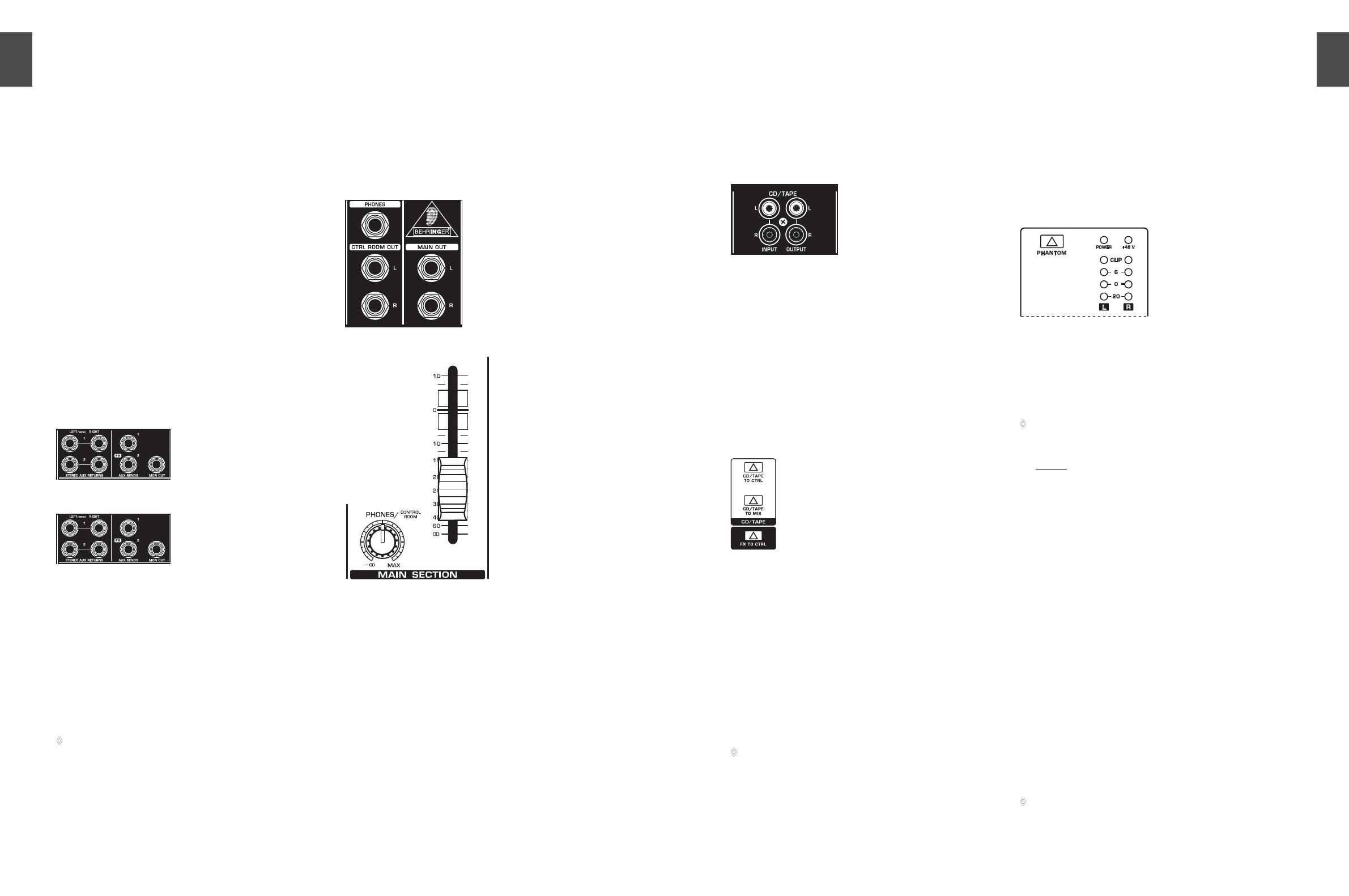
Monitor/main mix connectorsFig. 2.9:
Monitor control and main mix faderFig. 2.10:
PHONES/CONTROL ROOM
The stereo PHONES jack (at the top of the connector
panel) is where you connect headphones. The unbalanced
CTRL ROOM OUT jacks carry the summed effects and
main mix signals, as well as soloed channel signals. The
PHONES/CONTROL ROOM control adjusts the level of both
headphones and main monitor outputs. The 502 is not
equipped with control room outputs.
MAIN MIX
The MAIN OUT connectors are unbalanced mono jacks. The
main mix signal appears here at a level of 0 dBu. The MAIN
MIX fader adjusts the volume of these outputs. The XENYX
802 and 502 mixing consoles feature a rotary control for this
purpose.
CD/Tape connectors2.3.3
CD/TAPE INPUT
The CD/TAPE INPUTs are used to bring an external signal
source (e.g. CD player, tape deck, etc.) into the console. They
can also be used as a standard stereo line input, so the
output of a second XENYX or BEHRINGER ULTRALINK PRO
MX882 can be connected.
CD/Tape input/outputFig. 2.11:
Alternatively the line or tape output of a hi-fi amplifier with
source selection switch could also be hooked up here,
allowing you to easily listen to additional sources.
CD/TAPE OUTPUT
These connectors are wired in parallel with the MAIN OUT
and carry the main mix signal (unbalanced). Connect the
CD/TAPE OUTPUT to the inputs of your recording device.
The output level is adjusted via the high-precision MAIN MIX
fader or rotary control (802).
Signal assignment2.3.4
Assignment switches of the main sectionFig. 2.12:
CD/TAPE TO MIX
When the TAPE TO MIX switch is depressed, the 2-track input
is assigned to the main mix providing an additional input for
tape machines, MIDI instruments or other signal sources that
do not require any processing.
CD/TAPE TO CTRL ROOM (502: CD/TAPE TO PHONES)
Press the CD/TAPE TO CTRL ROOM/PHONES switch if you want
to monitor the 2-track input via the CTRL ROOM OUT. This
provides an easy way to monitor signals coming back from
tape to ensure that they are recording correctly.
If you are recording a signal via the CD/TAPE OUTPUT
and wish to listen to this simultaneously via the CD/
TAPE INPUT, do not use the CD/TAPE TO MIX switch.
Doing this would create a feedback loop, since the signal
would be routed, via the main mix, back to tape via the
CD/TAPE OUTPUT. To monitor the CD/TAPE INPUT, use
the CD/TAPE TO CTRL ROOM switch to assign the tape
signal to the monitor(s) or headphones. This will avoid
the tape signal being routed to the CD/TAPE OUTPUT.
FX TO CTRL ROOM
If you want to monitor only the FX send signal in your
headphones or monitor speaker(s), press the FX TO CTRL
switch. This mutes the main mix signal while routing the FX
SEND output to the monitor(s). The XENYX 802 and 502 do
not feature this switch.
Phantom power and LED displays2.3.5
Phantom power and control LEDsFig. 2.13:
+48 V
The red +48 V LED lights up when phantom power is on. The
PHANTOM switch activates the phantom power supply on
the XLR connectors of all mono channels.
Please do not connect microphones to the mixer (or
the stagebox/wallbox) as long as the phantom power
supply is switched on. Connect the micro-phones
before you switch on the power supply. In addition, the
monitor/PA loudspeakers should be muted before you
activate the phantom power supply. After switching
on, wait approx. one minute in order to allow system
stabilization.
POWER
The blue POWER LED indicates that the console is powered on.
Level indicator
The high-precision 4-segment display accurately displays the
relevant signal level.
LEVEL SETTING: To correctly set the gains of the channels,
first set the LEVEL controls of the input channels to their
center positions (0 dB). Then use the GAIN controls to
increase the input amplification until signal peaks show 0 dB
on the level meter.
When recording to digital recorders, the recorder’s peak
meter should not go into overload. While analog recorders
can be overloaded to some extent, creating only a certain
amount of distortion (which is common and often desirable),
digital recorders distort quickly when overloaded. In
addition, digital distortion is not only undesirable, but also
renders your recording completely useless.
The peak meters of your XENYX display the level
virtually independent of frequency. A recording level
of 0 dB is recommended for all signal types.
ENGLISH
XENYX 502/802/1002/1202 User Manual
8
ENGLISH
XENYX 502/802/1002/1202 User Manual
9
Installation3.
Mains connection3.1
AC POWER IN
Connect the power supply to the 3-pin mains connector
on the rear of the console. Use the AC adapter supplied to
connect the console to the mains. The adapter complies with
all applicable safety standards.
Please use only the power supply unit provided with
the console.
Never connect the XENYX to the power supply unit
while the latter is connected to the mains! First connect
the console to the power supply unit, then connect the
power supply unit to the mains.
Please note that both the power supply unit and the
mixing console heat up considerably during operation.
This is completely normal.
Audio connections3.2
You will need a large number of cables for dierent
applications. The illustrations below show how the connectors
should be wired. Be sure to use only high-grade cables.
Please use commercial RCA cables to connect the 2-track
inputs and outputs.
You can, of course, also connect unbalanced devices to the
balanced inputs/outputs. To do this, use either mono plugs
or stereo plugs with the ring and sleeve bridged (pins 1 and
3 in the case of XLR connectors).
Caution! Never use unbalanced XLR connectors (PIN 1
and 3 connected) on the MIC input connectors when
using the phantom power supply.
XLR connectionsFig. 3.1:
Strain relief clamp
Sleeve
Tip
Sleeve
(ground/shield)
Unbalanced ¼" TS connector
Tip
(signal)
¼" mono plugFig. 3.2:
¼" stereo plugFig. 3.3:
input
output
For unbalanced use, pin 1 and pin 3 have to be bridged
1 = ground/shield
2 = hot (+ve)
3 = cold (-ve)
12
3
1
2
3
Balanced use with XLR connectors
strain relief clamp
sleeve
ring
tip
sleeve
ground/shield
1/4" TRS headphones connector
ring
right signal
tip
left signal
Stereo plug for headphones connectionFig. 3.4:
Specifications4.
Mono inputs
Microphone inputs (XENYX Mic preamp)
Type XLR connector, electronically
balanced, discrete input circuit
Mic E.I.N.
1
(20 Hz - 20 kHz)
@ 0 Ω source resistance -134 dB / 135.7 dB A-weighted
@ 50 Ω source resistance -131 dB / 133.3 dB A-weighted
@ 150 Ω source resistance -129 dB / 130.5 dB A-weighted
Frequency response
<10 Hz - 150 kHz -1 dB
<10 Hz - 200 kHz -3 dB
Gain range +10 dB to +60 dB
Max. input level +12 dBu @ +10 dB GAIN
Impedance approx. 2.6 kΩ balanced
Signal-to-noise ratio 110 dB / 112 dB A-weighted
(0 dBu In @ +22 dB GAIN)
Distortion (THD+N) 0.005 % / 0.004 % A-weighted
Line input
Type ¼" TRS jack, electronically
balanced
Impedance approx. 20 kΩ balanced, approx.
10 kΩ unbalanced
Gain range -10 dB to +40 dB
Max. input level +22 dBu @ 0 dB GAIN
Fade-out attenuation
2
(Crosstalk attenuation)
Main fader closed 90 dB
Channel muted 89.5 dB
Channel fader muted 89 dB
Frequency response (Mic In Main Out)
<10 Hz - 90 kHz +0 dB / -1 dB
<10 Hz - 160 kHz +0 dB / -3 dB
Stereo inputs
Type ¼" TRS jack, electronically
balanced
Impedance approx. 20 kΩ
Max. input level +22 dBu
EqualizEr
EQ mono channels
LOW 80 Hz / ±15 dB
MID 2.5 kHz / ±15 dB
HIGH 12 kHz / ±15 dB
EQ stereo channels
LOW 80 Hz / ±15 dB
MID 2.5 kHz / ±15 dB
HIGH 12 kHz / ±15 dB
ENGLISH
XENYX 502/802/1002/1202 User Manual
10
ENGLISH
XENYX 502/802/1002/1202 User Manual
11
EN
Warranty§ 1
This limited warranty is valid only if you purchased the product from a BEHRINGER [1]�
authorized dealer in the country of purchase. A list of authorized dealers can be found
on BEHRINGER’s website www. behringer. com under “Where to Buy”, or you can contact
the BEHRINGER offi ce closest to you.
BEHRINGER* warrants the mechanical and electronic components of this product
[2]
to be free of defects in material and workmanship if used under normal operating
conditions for a period of one (1) year from the original date of purchase (see the
Limited Warranty terms in § 4 below), unless a longer minimum warranty period
is mandated by applicable local laws. If the product shows any defects within the
speci ed warranty period and that defect is not excluded under § 4, BEHRINGER
shall, at its discretion, either replace or repair the product using suitable new or
reconditioned product or parts. In case BEHRINGER decides to replace the entire
product, this limited warranty shall apply to the replacement product for the remaining
initial warranty period, i.e., one (1) year (or otherwise applicable minimum warranty
period) from the date of purchase of the original product.
Upon validation of the warranty claim, the repaired or replacement product will
[3]
be returned to the user freight prepaid by BEHRINGER.
Warranty claims other than those indicated above are expressly excluded.
[4]
PLEASE RETAIN YOUR SALES RECEIPT. IT IS YOUR PROOF OF PURCHASE COVERING
YOUR LIMITED WARRANTY. THIS LIMITED WARRANTY IS VOID WITHOUT SUCH PROOF
OF PURCHASE.
Online registration§ 2
Please do remember to register your new BEHRINGER equipment right after your
purchase at www. behringer. com under “Support” and kindly read the terms and
conditions of our limited warranty carefully. Registering your purchase and equipment
with us helps us process your repair claims quicker and more e ciently. Thank you for
your cooperation!
Return authorization number § 3
To obtain warranty service, please contact the retailer from whom the equipment [1]�
was purchased. Should your BEHRINGER dealer not be located in your vicinity, you
may contact the BEHRINGER distributor for your country listed under “Support” at
www. behringer. com. If your country is not listed, please check if your problem can
be dealt with by our “Online Support which may also be found under “Support”
at www. behringer. com. Alternatively, please submit an online warranty claim at
www. behringer. com BEFORE returning the product. All inquiries must be accompanied
by a description of the problem and the serial number of the product. After verifying
the product’s warranty eligibility with the original sales receipt, BEHRINGER will then
issue a Return Materials Authorization (“RMA”) number.
Subsequently, the product must be returned in its original shipping carton,
[2]
together with the return authorization number to the address indicated by BEHRINGER.
Shipments without freight prepaid will not be accepted.
[3]
Warranty Exclusions § 4
This limited warranty does not cover consumable parts including, but not limited [1]�
to, fuses and batteries. Where applicable, BEHRINGER warrants the valves or meters
contained in the product to be free from defects in material and workmanship for a
period of ninety (90) days from date of purchase.
This limited warranty does not cover the product if it has been electronically or
[2]
mechanically modifi ed in any way. If the product needs to be modifi ed or adapted in
order to comply with applicable technical or safety standards on a national or local
level, in any country which is not the country for which the product was originally
developed and manufactured, this modi cation/adaptation shall not be considered
a defect in materials or workmanship. This limited warranty does not cover any such
modifi cation/adaptation, regardless of whether it was carried out properly or not.
Under the terms of this limited warranty, BEHRINGER shall not be held responsible for
any cost resulting from such a modifi cation/adaptation.
This limited warranty covers only the product hardware. It does not cover
[3]
technical assistance for hardware or software usage and it does not cover any software
products whether or not contained in the product. Any such software is provided AS IS”
unless expressly provided for in any enclosed software limited warranty.
This limited warranty is invalid if the factory-applied serial number has been
[4]
altered or removed from the product.
Free inspections and maintenance/repair work are expressly excluded from this
[5]
limited warranty, in particular, if caused by improper handling of the product by the
user. This also applies to defects caused by normal wear and tear, in particular, of
faders, crossfaders, potentiometers, keys/buttons, tubes, guitar strings, illuminants and
similar parts.
Damage/defects caused by the following conditions are not covered by this
[6]
limited warranty:
improper handling, neglect or failure to operate the unit in compliance with
•
the instructions given in BEHRINGER user or service manuals;
connection or operation of the unit in any way that does not comply with the
•
technical or safety regulations applicable in the country where the product
is used;
damage/defects caused by acts of God/Nature (accident, fi re, fl ood, etc) or any
•
other condition that is beyond the control of BEHRINGER.
Any repair or opening of the unit carried out by unauthorized personnel
[7]
(user included) will void the limited warranty.
If an inspection of the product by BEHRINGER shows that the defect in question is
[8]
not covered by the limited warranty, the inspection costs are payable by the customer.
Products which do not meet the terms of this limited warranty will be repaired
[9]
exclusively at the buyer’s expense. BEHRINGER or its authorized service center will
inform the buyer of any such circumstance. If the buyer fails to submit a written repair
order within 6 weeks after notifi cation, BEHRINGER will return the unit C.O.D. with a
separate invoice for freight and packing. Such costs will also be invoiced separately
when the buyer has sent in a written repair order.
Authorized BEHRINGER dealers do not sell new products directly in online
[10 ]
auctions. Purchases made through an online auction are on a “buyer beware
basis. Online auction confi rmations or sales receipts are not accepted for warranty
veri cation and BEHRINGER will not repair or replace any product purchased through
an online auction.
Warranty transferability § 5
This limited warranty is extended exclusively to the original buyer (customer of
authorized retail dealer) and is not transferable to anyone who may subsequently
purchase this product. No other person (retail dealer, etc.) shall be entitled to give any
warranty promise on behalf of BEHRINGER.
Limited Warranty
sEnd / rEturn
Aux sends
Type ¼" TS jack, unbalanced
Impedance approx. 120 Ω
Max. output level +22 dBu
Stereo aux returns
Type ¼" TRS jack, electronically
balanced
Impedance approx. 20 kΩ balanced / approx.
10 kΩ unbalanced
Max. input level +22 dBu
outputs
Main outputs
Type ¼" TRS jack, unbalanced
Impedance approx. 120 Ω unbalanced
Max. output level +22 dBu
Control room outputs
Type ¼" TS jack, unbalanced
Impedance approx. 120 Ω
Max. output level +22 dBu
Headphones output
Type ¼" TRS jack, unbalanced
Max. output level +19 dBu / 150 Ω (+25 dBm)
Main mix system data
3
(Noise)
Main mix @ -∞, channel fader @ -∞ -106 dB / -109 dB A-weighted
Main mix @ 0 dB, channel fader @ -∞ -95 dB / -98 dB A-weighted
Main mix @ 0 dB, channel fader @ 0 dB -84 dB / -87 dB A-weighted
powEr supply
502 / 802 / 1002
Power consumption 13 W
USA/Canada
Adapter BEHRINGER PSU MX3UL
Mains voltage 120 V~, 60 Hz
Europe/U.K./Australia
Adapter BEHRINGER PSU MX3EU
Mains voltage 230 V~, 50 Hz
China
Adapter BEHRINGER PSU MX3CC
Input 220 V~ 50 Hz; 80 mA
Output 2 x 18.5 V~, 2 x 150 mA
Korea
Adapter BEHRINGER PSU MX3KR
Mains voltage 220 V~, 60 Hz
Japan
Adapter BEHRINGER PSU MX3JP
Mains voltage 100 V~, 50/60 Hz
1202
Power consumption 20 W
USA/Canada
Adapter BEHRINGER PSU MX5UL
Mains voltage 120 V~, 60 Hz
Europe/U.K./Australia
Adapter BEHRINGER PSU MX5EU
Mains voltage 230 V~, 50 Hz
China
Adapter BEHRINGER PSU MX5CC
Input 220 V~ 50 Hz; 150 mA
Output 2 x 17.5 V~, 2 x 650 mA
Korea
Adapter BEHRINGER PSU MX5KR
Mains voltage 220 V~, 60 Hz
Japan
Adapter BEHRINGER PSU MX5JP
Mains voltage 100 V~, 50/60 Hz
physical/wEight
502
Dimensions (H x W x D) 1.9" / 1.5" x 5.3" x 7" (47 mm /
37 mm x 134 mm x 177 mm)
Weight (net) 1.2 lbs (0.55 kg)
802
Dimensions (H x W x D) 1.9" / 1.5" x 7.4" x 8.7" (47 mm /
37 mm x 189 mm x 220 mm)
Weight (net) 2.2 lbs (1.00 kg)
1002
Dimensions (H x W x D) 1.9" / 1.5" x 7.4" x 8.7" (47 mm /
37 mm x 189 mm x 220 mm)
Weight (net) 2.3 lbs (1.05 kg)
1202
Dimensions (H x W x D) 1.9" / 1.5" x 9.5" x 8.7" (47 mm /
37 mm x 242 mm x 220 mm)
Weight (net) 3 lbs (1.35 kg)
1
Equivalent Input Noise
2
Measuring conditions: 1 kHz rel. to 0 dBu; 20 Hz - 20 kHz; line input; main output; unity gain.
3
20 Hz - 20 kHz; measured at main output. Channels 1 - 4 unity gain; EQ flat; all channels on main mix;
channels 1/3 as far left as possible; channels 2/4 as far right as possible; reference = +6 dBu.
BEHRINGER is constantly striving to maintain the highest professional standards. As a result of these efforts,
modifications may be made from time to time to existing products without prior notice. Specifications and
appearance may differ from those listed or illustrated.
ENGLISH
XENYX 502/802/1002/1202 User Manual
12
ENGLISH
XENYX 502/802/1002/1202 User Manual
13
Claim for damage § 6
Subject only to the operation of mandatory applicable local laws, BEHRINGER shall
have no liability to the buyer under this warranty for any consequential or indirect loss
or damage of any kind. In no event shall the liability of BEHRINGER under this limited
warranty exceed the invoiced value of the product.
Limitation of liability § 7
This limited warranty is the complete and exclusive warranty between you and
BEHRINGER. It supersedes all other written or oral communications related to this
product. BEHRINGER provides no other warranties for this product.
Other warranty rights and national law§ 8
This limited warranty does not exclude or limit the buyers statutory rights as a [1]�
consumer in any way.
The limited warranty regulations mentioned herein are applicable unless they
[2]
constitute an infringement of applicable mandatory local laws.
This warranty does not detract from the seller’s obligations in regard to any lack of
[3]
conformity of the product and any hidden defect.
Amendment § 9
Warranty service conditions are subject to change without notice. For the latest
warranty terms and conditions and additional information regarding BEHRINGER’s
limited warranty, please see complete details online at www. behringer. com.
* BEHRINGER Macao Commercial O shore Limited of Rue de Pequim No. 202-A, Macau Finance Centre 9/J,
Macau, including all BEHRINGER group companies
Technical speci cations and appearance are subject to change without
notice. The information contained herein is correct at the time of printing.
BEHRINGER accepts no liability for any loss which may be suff ered by any
person who relies either wholly or in part upon any description, photograph
or statement contained herein. Colors and specifi cations may vary slightly
from product. BEHRINGER products are sold through authorized dealers
only. Distributors and dealers are not agents of BEHRINGER and have
absolutely no authority to bind BEHRINGER by any express or implied
undertaking or representation. This manual is copyrighted. No part of
this manual may be reproduced or transmitted in any form or by any
means, electronic or mechanical, including photocopying and recording
of any kind, for any purpose, without the express written permission of
Red Chip Company Ltd.
ALL RIGHTS RESERVED. © 2009 Red Chip Company Ltd.
Trident Chambers, Wickhams Cay, P.O. Box 146,
Road Town, Tortola, British Virgin Islands
Legal Disclaimer
FEDERAL COMMUNICATIONS
COMMISSION COMPLIANCE
INFORMATION
Responsible party name: BEHRINGER USA, Inc.
Address: 18912 North Creek Parkway,
Suite 200 Bothell, WA 98011,
USA
Phone/Fax No.: Phone: +1 425 672 0816
Fax: +1 425 673 7647
hereby declares that the product
XENYX 502/802/1002/1202
complies with the FCC rules as mentioned in the following
paragraph:
This equipment has been tested and found to comply
with the limits for a Class B digital device, pursuant to part
15 of the FCC Rules. These limits are designed to provide
reasonable protection against harmful interference in a
residential installation. This equipment generates, uses
and can radiate radio frequency energy and, if not installed
and used in accordance with the instructions, may cause
harmful interference to radio communications. However,
there is no guarantee that interference will not occur in a
particular installation. If this equipment does cause harmful
interference to radio or television reception, which can be
determined by turning the equipment off and on, the user is
encouraged to try to correct the interference by one or more
of the following measures:
Reorient or relocate the receiving antenna.•
Increase the separation between the equipment and •
receiver.
Connect the equipment into an outlet on a circuit different •
from that to which the receiver is connected.
Consult the dealer or an experienced radio/TV technician •
for help.
This device complies with Part 15 of the FCC rules. Operation
is subject to the following two conditions:
(1) this device may not cause harmful interference, and
(2) this device must accept any interference received,
including interference that may cause undesired operation.
XENYX 502/802/1002/1202
ENGLISH
This manual is available in English, German, French, Spanish, Italian, Russian,
Polish, Dutch, Finnish, Swedish, Danish, Portuguese, Greek, Japanese
and Chinese. There may also be more current versions of this document.
Download them by going to the appropriate product page at:
www.behringer.com
  • Page 1 1
  • Page 2 2
  • Page 3 3
  • Page 4 4
  • Page 5 5
  • Page 6 6
  • Page 7 7
  • Page 8 8

Behringer 1002 User manual

Category
Audio mixers
Type
User manual
This manual is also suitable for

Ask a question and I''ll find the answer in the document

Finding information in a document is now easier with AI