
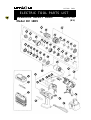
POWER TOOLS
TECHNICAL DATA
AND
SERVICE MANUAL
CORDLESS IMPACT DRILL
DV 18DV
SPECIFICATIONS AND PARTS ARE SUBJECT TO CHANGE FOR IMPROVEMENT
LIST No. F854
Jul. 2001
D
MODEL
DV 18DV

Notice for use
Specifications and parts are subject to change for improvement.
Refer to Hitachi Power Tool Technical News for further information.

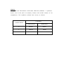
REMARK:
Throughout this TECHNICAL DATA AND SERVICE MANUAL, a symbol(s)
is(are) used in the place of company name(s) and model name(s) of our
competitor(s). The symbol(s) utilized here is(are) as follows:
Symbols Utilized
Competitors
Company Name
Model Name
DEWALT
DW997
P
MAKITA
8443D
C

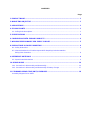
Page
CONTENTS
1. PRODUCT NAME........................................................................................................................... 1
2. MARKETING OBJECTIVE ............................................................................................................. 1
3. APPLICATIONS.............................................................................................................................. 1
4. SELLING POINTS .......................................................................................................................... 1
4-1. Selling Point Descriptions ............................................................................................................... 2
5. SPECIFICATIONS .......................................................................................................................... 3
6. COMPARISONS WITH SIMILAR PRODUCTS .............................................................................. 4
7. WORKING PERFORMANCE PER SINGLE CHARGE .................................................................. 5
8. PRECAUTIONS IN SALES PROMOTION ..................................................................................... 6
8-1. Safety Instructions .......................................................................................................................... 6
8-2. Inherent Drawbacks of Cordless Impact Drills Requiring Particular Attention
during Sales Promotion................................................................................................................... 8
9. REFERENCE MATERIALS ............................................................................................................ 9
9-1. Speed Control Mechanism ............................................................................................................. 9
10. REPAIR GUIDE .......................................................................................................................... 10
10-1. Precautions in Disassembly and Reassembly ............................................................................ 10
10-2. Precautions in Disassembly and Reassembly of Battery Charger ............................................. 17
11. STANDARD REPAIR TIME (UNIT) SCHEDULES...................................................................... 18
Assembly Diagram for DV 18DV

--- 1 ---
1. PRODUCT NAME
Hitachi 18 V Cordless Impact Drill, Model DV 18DV
2. MARKETING OBJECTIVE
European competitors are now preparing to have a wide selection of cordless impact drills (combination drills),
and it is expected that cordless impact drills will be the growing segment of the power tool industry.
The Model DV 18DV cordless impact drill has been newly developed as a higher level version of the Model
DV 14DV (14.4 V product) that is brought out together with the Model DV 18DV. The Model DV 18DV is equipped
with the T-type handle and the 22-step clutch for easier operation as a driver drill.
3. APPLICATIONS
Tightening and loosening wood screws, self-tapping screws and machine screws
Drilling into wood materials, plastic, mild steel and aluminum
Drilling into brick and concrete block
4. SELLING POINTS
Two-speed transmission with
one-touch speed shift knob
Equipped with feedback
power control
18 V cassette battery
Push-button type
reversing switch
Soft-grip handle
Durable fan-cooled
powerful motor
13 mm (1/2") keyless chuck
Variable speed switch
with braking function
3-mode selection
Drill
Impact drill
Driver (22-stage torque adjustable clutch)

--- 2 ---
Lower torque
Cap
Higher torque
Drill mark
Impact mark
Triangle mark
4-1. Selling Point Descriptions
4-1-1. 3-mode selection
This model can be easily switched between three modes, screwdriving, drilling and impact drilling, by simply
turning the cap dial. To use it as a screwdriver, set the cap to any position between 1 and 22, depending on the
types of screws and the material to be fastened. The clutch is then engaged to adjust the tightening force among
the corresponding twenty-two torque levels.
In order to fasten large diameter wood screws or drill into metal, wood and plastic, align the cap's drill mark
" " with the triangle mark on the main body. The clutch is then directly coupled to provide the maximum
power output. Drilling into very hard materials such as brick and concrete block can be efficiently carried out by
aligning the cap impact mark " " with the triangle mark on the main body. (See Fig. 1.)
Fig. 1
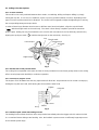
4-1-2. Durable fan-cooled powerful motor
The cooling fan incorporated in the motor and the air vents provided in its outer frame greatly enhance the cooling
effect, ensuring improved durability in continuous operation.
4-1-3. 13 mm (1/2") keyless chuck
The keyless chuck facilitates fast and easy replacement of driver bits. Replacement can be carried out simply by
holding the ring with one hand, while turning the sleeve with the other hand.
4-1-4. Variable speed switch with braking function
The braking function allows the driver unit to stop rotation immediately when the trigger switch is released, which
is a convenient feature during actual working. Also, the feedback system ensures a sufficiently large torque even
in the variable speed range.
Fig. 2
Ring
Sleeve
Tighten
Loosen
Driver bit

--- 3 ---
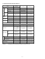
Keyless chuck
(13VLRF-N)
Rotation speed (No-load)
Type of motor
Torque
Type of switch
Handle configuration
Enclosure
Battery
(
Type EB 1814/EB 1820
)
Charger
(Model UC 24YFA)
Battery
(
Type EB18H/EB 1830H
)
Impact rate (No-load)
Screwdriver Machine screw
••••••••
6 mm (1/4")
Wood screw
••••••••••••
8 mm dia. x 75 mm (#20 x 3")
Brick........................ 16 mm (5/8") [Depth 30 mm (1-1/4")]
Drill Metal
••••••
Mild steel 13 mm (1/2") [Thickness 1.6 mm (1/16")]
Aluminum 13 mm (1/2") [Thickness 1.6 mm (1/16")]
Wood
••••••••••••••••••••••
38 mm (1-1/2") [Thickness 18 mm (11/16")]
Mount type
••••••
Screw-on (UNF 1/2" --- 20)
Diameter
•••••••••
1.5 --- 13 mm (1/16" --- 1/2")
Low: 0 --- 400/min. High: 0 --- 1,500/min.
Low: 0 --- 6,000/min. High: 0 --- 22,500/min.
DC magnet motor
Slip torque
••••••••
1.0 --- 5.9 N
•
m (10 --- 60 kgf
•
cm, 9 --- 52 in-lbs.) [22 stages]
Max. torque
•••••••
High: 11 N
•
m (110 kgf
•
cm, 96 in-lbs.) Low: 45 N
•
m (460 kgf
•
cm, 400 in-lbs.)
Trigger switch with push button for forward and reverse rotation changeover (w/o stopper)
T-type
Body
•••••••••••
Glassfiber reinforced polycarbonate resin (green) and thermoplastic elastomer (black)
Battery
••••••••
Glassfiber reinforced polyamide resin (black)
Charger
••••••
ABS resin (black)
Sealed cylindrical nickel-cadmium storage battery
Nominal voltage
•••••••••••••••
DC 18 V
Nominal life
•••••••••••••••••••••
Charging/discharging: Approx. 500/1,000 times
(in case of Model UC 24YFA)
Nominal capacity
•••••••••••••
1.4/2.0 Ah
Sealed cylindrical nickel-metal-hydride storage battery
Nominal voltage
•••••••••••••••
DC 18 V
Nominal life
•••••••••••••••••••••
Charging/discharging: Approx. 500 times
(in case of Model UC 24YFA)
Nominal capacity
•••••••••••••
2.2/3.0 Ah
Overcharge protection system: (1) Battery voltage detection (
2
V system)
(2) Battery surface temperature detection
(thermostat or thermistor)
(3) 120 minutes timer
Power input: 90 W
Charging time: Approx. 40 minutes [for type EB 1814 battery at 20˚C (68˚F)]
Approx. 50 minutes [for type EB 1820 battery at 20˚C (68˚F)]
Approx. 55 minutes [for type EB 18H battery at 20˚C (68˚F)]
Approx. 70 minutes [for type EB 1830H battery at 20˚C (68˚F)]
Operable ambient temperature range: 0 ˚C
---
40˚C (32˚F
---
104˚F)
The maximum allowable temperature of the type EB 1814 or EB 1820 battery is 60˚C
(140˚F) and the type EB18H or EB 1830H battery is 45˚C (113˚F).
Indication method of battery charging function:
5. SPECIFICATIONS
Capacity
Weight
Standard accessories
Main body unit (including battery) ........................................................2.4 kg (5.3 Ibs.)
Charger unit
(including cord)................................................................0.6 kg (1.3 Ibs.)
Gross with charger and case ...............................................................5.8 kg (12.9 Ibs.)
Charger (UC 24YFA).....................................................................................................1
Battery........................................................................................................................... 1
Phillips (plus) driver bit (No. 2) ......................................................................................1
Case..............................................................................................................................1

--- 4 ---
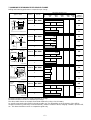
6. COMPARISONS WITH SIMILAR PRODUCTS
Drill chuck
Low
High
0 --- 450 /min
0 --- 1,400 /min
Keyless
13 mm (1/2")
Battery
Motor
2-speed transmission
Electric brake
Slip torque
Max. torque
Low
High
Nominal capacity
Nominal voltage
Charging time*
Battery mount
Overall length
Weight
Gear changeover type 2-speed transmission
Equipped
1.0 --- 5.9 N
•
m
(10 --- 60 kgf
•
cm)
(9 --- 52 in-lbs.)
[22 positions]
45 N
•
m
(460 kgf
•
cm)
(400 in-lbs.)
11 N
•
m
(110 kgf
•
cm)
(96 in-lbs.)
1.4 /2.0/2.2/3.0 Ah
18 V
40/50/55/70 minutes
Cassette type
255 mm (10-3/64")
2.4 kg (5.3 lbs.)
Equipped
37 N
•
m
(377 kgf
•
cm)
(325 in-lbs.)
2.0 Ah
18 V
60 minutes
Cassette type
262 mm (10-5/16")
2.5 kg (5.6 lbs.)
DC magnet motor
Equipped
Not indicated
[16 positions]
Not indicated
2.0/2.6/3.0Ah
18 V
60/75/90 minutes
Cassette type
267 mm
(10-33/64")
2.6 kg (5.7 lbs.)
45 N
•
m
(460 kgf
•
cm)
(400 in-lbs.)
Rotation
speed
Low
High
Impact rate
Type
Capacity
0 --- 6,750 /min
0 --- 21,000 /min
Keyless
13 mm (1/2")
DC magnet motor
0 --- 400 /min
0 --- 1,500 /min
0 --- 6,000 /min
0 --- 22,500 /min
Keyless
13 mm (1/2")
DC magnet motor
0 --- 600 /min
0 --- 1,800 /min
0 --- 7,150 /min
0 --- 20,350 /min
Maker
Model
Max. capacity
Drilling
Mild steel
Aluminum
Soft wood
HITACHI
DV 18DV
16 mm (5/8")
13 mm (1/2")
13 mm (1/2")
16 mm (5/8")
38 mm (1-1/2")
13 mm (1/2")
Screw
driving
Not indicated
Not indicated
Machine screw
Wood screw
8 mm dia. x 75 mm length
(#20 x 3")
38 mm (1-1/2")
Not indicated6 mm (1/4")
Brick
Not indicated
16 mm (5/8")
38 mm (1-1/2")
13 mm (1/2")
Not indicated
Remarks*
••••••••
Charging time varies depending on the type of charger to be used.
Not indicated
Not indicated
[15 positions]
Not indicated
CP

--- 5 ---
7. WORKING PERFORMANCE PER SINGLE CHARGE
Drilling and fastening performance comparison per charge
Remarks* Number of machine screws fastened per charge
Remarks*1 Number of holes or fasteners per charge
The above table shows an example of test data obtained by using a 2.0 Ah battery.
As actually measured values listed in the above table may vary depending on the sharpness of the drill bit,
workpiece hardness (particularly in wood materials), moisture content of wood, charging condition, operator skill,
etc. This data should be used as a comparative guide only.
Type of work Maker Model
Working capacity (*1)
Drilling
speed
(sec./pc.)
*0
0
*400
100
*1000
250
*800
200
*200
50
*600
150
<High speed>
<Low speed>
<Low speed>
3.8
3.8
4.7
5.4
5.1
5.3
0.5
0.6
0.6
120
140
95
55
60
50
*950
*550
*530
3.3
4.4
5.3
150
150
110
T18 (11/16")
36 mm dia. (13/32")
American
pine
Wood boring
75 mm (3")
8 mm dia. (# 20)
American
pine
Wood screw
A 5 mm-dia. prepared
hole is provided.
6 mm (1/4")
12 mm (15/32")
Machine
screw
<High speed>
7.1
8.2
8.0
95
100
85
T1.6 (1/16")
10 mm dia. (5/16")
Mild steel
HSS
drill bit
<High speed>
D30 mm (1-1/4")
10 mm dia.
(3/8")
Brick
Drill bit for concrete
C
P
DV 18DV
HITACHI
C
P
DV 18DV
HITACHI
C
P
DV 18DV
HITACHI
C
P
DV 18DV
HITACHI
C
P
DV 18DV
HITACHI

--- 6 ---
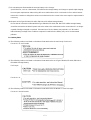
8. PRECAUTIONS IN SALES PROMOTION
8-1. Safety Instructions
In the interest of promoting the safest and most efficient use of the Model DV 18DV Cordless Impact Drill by all of
our customers, it is very important that at the time of sale, the salesperson carefully ensures that the buyer
seriously recognizes the importance of the contents of the Handling Instructions, and fully understands the
meaning of the precautions listed on the Caution Plate and Name Plate attached to each tool.
A. Handling instructions
Salespersons must be thoroughly familiar with the contents of the Handling Instructions in order to give pertinent
advice to the customer. In particular, they must have a thorough understanding of the precautions for use of the
cordless tools which are different from those of ordinary electric power tools.
(1) Before use, ensure that the unit is fully charged.
New units are not fully charged. Even if the units were fully charged at the factory, long periods of inactivity,
such as during shipping, cause the storage battery to lose its charge. Customers must be instructed to fully
charge the unit prior to use.
(2) Connect the charger to an AC power outlet only.
Use of any other power source (DC outlet, fuel powered generator, etc.) will cause the charger to overheat and
burn out.
(3) Do not use any voltage increasing equipment (transformer, etc.) between the power source and the charger.
If the charger is used with voltage higher than that indicated on the unit, it will not function properly.
(4) Conduct battery charging at an ambient temperature range of 0 ˚C --- 40 ˚C (32 ˚F --- 104 ˚F).
Special temperature sensitive devices are employed in the charger to permit rapid charging. Ensure that
customers are instructed to use the charger at the indicated ambient temperature range. At temperature
under 0 ˚C (32 ˚F) the thermostat will not function properly, and the storage battery may be overcharged.
At temperature over 40 ˚C (104 ˚F), the storage battery cannot be sufficiently charged. The optimum
temperature range is 20 ˚C --- 25 ˚C (68 ˚F --- 77 ˚F).
(5) The battery charger should not be used continuously.
At high ambient temperature, if over three storage batteries are charged in succession, the temperature of the
coils on the transformer will rise and there is a chance that the temperature fuse inserted in the interior of the
transformer will inadvertently melt. After charging one battery, please wait about 15 minutes before charging
the next battery.
(6) Do not insert foreign objects into the air vents on the charger.
The charger case is equipped with air vents to protect the internal electronic components from overheating.
Caution the customer not to allow foreign materials, such as metallic or flammable objects, to be dropped or
inserted into the air vents. This could cause electrical shock, fire, or other serious hazards.

--- 7 ---
(7) Do not attempt to disassemble the storage battery or the charger.
Special devices, such as a thermostat, are built into the storage battery and charger to permit rapid charging.
Incorrect parts replacement and/or wiring will cause malfunctions which could result in fire or other hazards.
Instruct the customer to bring these units to an authorized service center in the event repair or replacement is
necessary.
(8) Disposal of the Type EB 1814, EB 1820, EB 18H or EB 1830H storage battery
Ensure that all customers understand that Type EB 1814, EB 1820, EB 18H or EB 1830H storage battery
should be returned to the Hitachi power tool sales outlet or the authorized service center when it is no longer
capable of being recharged or repaired. If thrown into a fire, the battery may explode, or, if discarded
indiscriminately, leakage of the cadmium compound contained in the battery may cause environmental
pollution.
B. Caution plates
(1) The following cautions are listed on the Name Plate attached to the main body of each tool.
For the U.S.A. and Canada
(2) The following cautions are listed on the Name Plate attached to each Type EB 1814, EB 1820, EB 18H or
EB 1830H Storage Battery.
For Europe
For the U.S.A.
(3) The following cautions are listed on the Name Plate attached to the Model UC 24YFA charger.
For the U.S.A and Canada

--- 8 ---
8-2. Inherent Drawbacks of Cordless Impact Drills Requiring Particular Attention during Sales Promotion
The cordless impact drill offers many advantages; it can be used in places where no power source is available,
the absence of a cord allows easy use, etc. However, any cordless tool has certain inherent drawbacks.
Salespersons must be thoroughly familiar with these drawbacks in order to properly advise the customer in the
most efficient use of the tool.
A. Suggestions and precautions for the efficient use of the tool
(1) Use the Cordless Impact Drill for comparatively light work.
Because they are battery driven, the output of the motor in cordless impact drills is rather low in comparison
with conventional electric power tools. Accordingly, they are not suitable for continuous drilling of many holes
in succession, or for drilling into particularly hard materials which creates a heavy load. Salespersons should
recommend conventional electric power tools for such heavy work.
(2) Drilling of large diameter holes should be conducted at low speed.
Instruct the customer that drilling of large diameter holes or other work which requires particularly strong
torque should be done at low speed. Because there is less torque at high speed, attempting such work at high
speed will not improve working efficiency.
(3) Do not insert a foreign object into body vent holes.
The body of this tool has vent holes for improving the cooling efficiency. As a fan is built into the motor, a
foreign object inserted through a vent hole may cause a failure. Please instruct customers to never insert a
foreign object into the vent hole.
(4) Use a thrust of 100 to 150 N (10 --- 15 kgf, 22 --- 33 lbs).
It would not accelerate the drilling speed of this unit to press the tool strongly against the workpiece as is done
with a usual AC impact drill. It would instead damage the drill bit, resulting not only in a poorer working
efficiency but could also cause burning out of the motor.
(5) Avoid "locking" of the motor.
Locking of the motor will cause an overload current that could result in burning of the motor and/or rapid
deterioration of the battery. Salespersons should advise the customer to immediately release the switch and
stop operation if the motor becomes locked. (A jammed drill bit can be disengaged from the workpiece
material by setting the switch to reverse rotation, or by manually turning the main body of the tool.)
(6) Variation in amount of work possible per charge
Although the nominal chargeable capacity of the storage batteries used with the Model DV 18DV is 1.4 Ah,
2.0 Ah, 2.2 Ah or 3.0 Ah, the actual capacity may vary within 10% of that value depending on the ambient
temperature during use and charging, and the number of times the batteries have been recharged. It should
be noted that other factors which may have a bearing on the amount of work possible per charge are the
working conditions (ambient temperature, type and moisture content of the workpiece, sharpness of the drill
bit, etc.) and the operational skill of the user.

--- 9 ---
(7) Precautions in the use of HSS Drill Bits
Although the Model DV 18DV is designed for drilling capacities of 38 mm (1-1/2") in wood, and 13 mm (1/2")
in aluminum and mild steel, this capability is not as efficient as conventional electric power tools. In particular,
when drilling through aluminum material with a 13 mm (1/2") drill bit, the drill tends to become locked when the
drill bit penetrates through the material. For this reason, the customer should be cautioned to reduce the
thrust on the main body of the drill when drilling completely through the material to avoid locking the tool.
Repeated locking of the drill causes excessive current flow from the batteries which not only decreases the
amount of work possible per charge, but could also result in burning of the motor.
B. Suggestions and precautions for the efficient use of the charger and storage batteries
If any of the storage batteries Types EB 1814, EB 1820, EB 18H and EB 1830H is exposed to direct sunlight
for an extended period or if the temperature of the battery is high immediately after it has been used in the
tool, the pilot lamp (red) may not be turned on when the battery is connected to the charger. Chargeable
temperature ranges of each type of battery are specified as follows.
Types EB 1814 and EB 1820: from -5˚C to 60˚C (from 23˚F to 140˚F)
Types EB 18H and EB 1830H: from 0˚C to 45˚C (from 32˚F to 113˚F)
In such a case, the customer should be advised to place the battery in a shaded area with a good airflow, and
allow sufficient cooling before recharging. This phenomenon is common to all existing batteries that employ a
thermostat. The cooling time required before charging varies from a few minutes to about 30 minutes,
depending on the load, duration of use, and ambient temperature.
9. REFERENCE MATERIALS
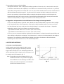
9-1. Speed Control Mechanism
Spindle rotation speed of the Model DV 18DV can be
controlled by simply varying the amount by which the
trigger switch is depressed. The relationship between the
amount the trigger switch is depressed (in millimeters) and
the rotation speed is illustrated in Fig. 3.
Note: The gradient and values illustrated in Fig. 3 are
intended for reference only, and will vary slightly
due to differences in the discharge condition of the
battery, the ambient temperature, and individual
speed-control element accuracy.
Fig. 3

--- 10 ---
10. REPAIR GUIDE
Be sure to remove the storage batteries from the main body before servicing. Inadvertent triggering of the switch
with the storage battery connected will result in a danger of accidental turning of the motor.
10-1. Precautions in Disassembly and Reassembly
The [Bold] numbers in the description below correspond to the item numbers in the Parts List and exploded
assembly diagram for the Model DV 18DV.
10-1-1. Disassembly
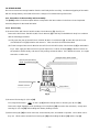
(1) Removal of the Drill Chuck 13VLRF-N (W/O Chuck Wrench) [2] (See Fig. 4.)
Remove the Drill Chuck 13VLRF-N (W/O Chuck Wrench) [2] of the fully assembled main body in accordance
with the following procedures.
(a) Fully open the jaws of the Drill Chuck 13VLRF-N (W/O Chuck Wrench) [2], and turn the Special Screw
(Left Hand) M6 x 23 [1] clockwise and remove it. Take care that it is left-hand threaded.
(b) Fix the hexagonal bar wrench M10 into the Drill Chuck 13VLRF-N (W/O Chuck Wrench) [2] as indicated in
Fig.4. Next, apply the Wrench 14 mm (special repair tool, Code No. 873929) [601] to the flat surfaces on
the spindle to hold it steady, and remove it by turning counterclockwise. If it is difficult to loosen, use a pipe
extension or similar tool.
(2) Removal of Housing (A). (B) Set [35]
First, align the drill mark " " on the Cap [4] with the triangle mark on Housing (A). (B) Set [35].
Remove the eight Tapping Screws (W/Flange) D3 x 16 (Black) [32] secured to the main body. Gently open
Housing (A). (B) Set [35] while holding their battery loading sections.
(3) After Housing (B) [35] has been removed, all the internal parts, assembled or separate, can be taken out as
they are. Lift the entire contents from Housing (A) [35] while holding the Motor [31] and the Cap [4].
Hexagonal bar wrench M10
Wrench 14 mm
Drill Chuck 13VLRF-N
(W/O Chuck Wrench) [2]
Flat surface
Fig. 4

--- 11 ---
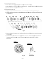
(4) Disassembly of the gear unit
(a) Remove the Cap [4] from the Front Case [12]. Take care not to remove the Switch Plate [8] and the Nut
[9] from the Front Case [12] in this operation.
(b) Turn the Motor [31] counterclockwise when viewed from the rear and remove it from the Rear Case [20].
(c)
Remove the Shift Arm [22] from the Rear Case [20], and remove the Shift Knob [41] from the Shift Arm [22]
.
(d) Remove the Screw Set M3 x 12 (4 pcs.) [21] connecting the Front Case [12] and the Rear Case [20].
(e) Remove Washer (A) [19], Planet Gear (C) Set (3 pcs.) [18], Carrier [17], Ring Gear [16], Spacer Washer
[15], six Steel Balls D5 [14] and six Rollers [13] in sequence from the Front Case [12]. Take care not to
lose the six Steel Balls D5 [14] and the six Rollers [13] in this operation.
(5) Removal of the Switch Plate [8]
Turn the switch flange so as to fit the projection of the switch flange to the recess of the Switch Plate [8], then
remove the Switch Plate [8] from the Front Case [12]. (See Fig. 5.)
(7) Removal of the O-ring [6]
Pull out the Lock Washer [7] from the Cap [4] and remove the
O-ring [6]. (See Fig. 6.)
(8) Disassembly of the power supply unit
(Note) Do not remove the fin secured to the DC-speed Control
Switch [38] with a screw.
Remove the two Machine Screws (W/SP. Washer) M4 x 6 [34],
and take the Motor [31] and the Motor Spacer [30] apart.
Disconnect the Internal Wires (Black) [36] and (Red) [37] from
the Motor [31] with a soldering iron, then disconnect them from
the DC-speed Control Switch [38] with a soldering iron in the
same manner.
Fig. 5
Switch Plate [8]
Three projections of Nut [9]
Fig. 6
Lock Washer [7]
Cap [4]
O-ring [6]
Projection of switch frange
Marking of
Rear Case [20]
Recess of
Switch Plate [8]
Projections of Front Case [12]
Switch flange
(6) Removal of the Spring [10] and the Thrust Washer [11]
Turn the Nut [9] counterclockwise and remove it from the Front Case [12], then remove the Spring [10] and
Thrust Washer [11] from the Front Case [12].
(Note) Do not disassemble the Front Case [12].

--- 12 ---
10-1-2. Reassembly
Reassembly can generally be carried out as the reverse of the disassembly procedure, with some items to be
noted as follows.
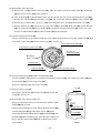
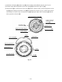
(1) Reassembly of the power supply unit
(a) Be sure to perform wiring connections as indicated in the wiring diagram. (See Fig. 7.)
Fig. 7
Motor Spacer [30] Motor [31]
Internal Wire (Red ) [37]
Machine Screw
(W/SP. Washer)
M4 x 6 [34]
Internal Wire (Red) [37]
Internal
Wire (Black) [36]
Internal Wire (Black) [36]
Ferrite Core [40]
DC-speed Control Switch [38]
Terminal Support (A) [43]
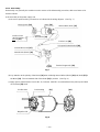
(b) Pay attention to the polarity of the Motor [31] when soldering Internal Wires (Black) [36] and (Red) [37] to
the Motor [31]. The red-marked side of the Motor [31] is positive. (See Fig. 8.)
(c) Apply grease (Hitachi Motor Grease No. 29, Code No. 930035 is recommended) to the pinion press-fitted
on the Motor [31] shaft.
Fig. 8
Positive side
Red marking
Negative side
[30]
[31]

--- 13 ---
(2) Reassembly of the clutch unit
Mount the Thrust Washer [11], Spring [10] and Nut [9] to the Front Case [12].
Screw the Nut [9] in the Front Case [12] about 1-3/8 turns (495˚). Mount the Switch Plate [8] aligning with the
projections of the Front Case [12] as shown in Fig. 5.
(3) Reassembly of the gear unit
(a) Apply grease (Hitachi Motor Grease No. 29, Code No. 930035) to the meshing parts of the gear.
(b) Install the parts series from the six Rollers [13] to Washer (B) [29] into the assembly reassembled in step
(2). (See Fig. 9.)
(i) Note the direction of the groove when installing the Slide Ring Gear [23] so that the groove faces toward
the Motor [31].
(ii) Install Washer (B) [29] in the Rear Case [20] with the projections of Washer (B) [29] engaged with the
recesses in the Rear Case [20], and turn Washer (B) [29] clockwise until it can turn no further.
(See Fig. 10.)
Fig. 9
[12] [13] [14] [15] [16] [17] [18]
[26] [27][25]
[20] [21]
[23]
[9] [11][10]
[28] [29][24]
Groove
Fig. 10
Recess
Projection
[29]
Projection
[8]
[19]

--- 14 ---
(c) Install the Click Spring [5] and the Cap [4] to the assembly reassembled in step (b). (See Fig. 11.)
(i) Insert the ridge and the projections of the Click Spring [5] into the holes of the Cap [4].
(ii) When the Nut [9] is screwed in the Front Case [12] about 1-3/8 turns (495˚), the three projections of the
Nut [9] and the marking of the Rear Case [20] are positioned as shown in Fig. 11. Set the narrow slit of
switch flange as shown in Fig. 11. Mount the Cap [4] aligning the ridge of the Click Spring [5] with the
three projections of the Nut [9].
Fig. 11
Click Spring [5]
Marking of the
Rear Case [20]
Holes
Ridge
Three projections of Nut [9]
Cap [4]
Wide slit of switch flange
Lock Washer [7]
Switch flange
Narrow slit of
switch flange
Narrow projections
of Cap [4]
Narrow slit of
Lock Washer [7]
Projections
Center of the flat
surface of Front
Case [12]
Front Case [12]

--- 15 ---
(d) Install the Shift Arm [22] into the assembly reassembled in step (c).
With the ridge at the Shift Arm [22] facing the Motor [31] side, first install them on the unmarked side of the
assembly reassembled in step (c). Then insert the projections on the Shift Arm [22] into the holes in the
Rear Case [20] and make sure that the projections are fitted into the grooves in the Slide Ring Gear [23]
mounted within the Rear Case [20]. (See Fig. 12.)
Fig. 12
[22]
Ridge
[22]
Hole
Groove
Mark
(e) Install the Drill Chuck 13VLRF-N (W/O Chuck Wrench) [2].
Install the Drill Chuck 13VLRF-N (W/O Chuck Wrench) [2] using the Wrench 14 mm (special repair tool,
Code No. 873929) and secure it with the Special Screw (Left Hand) M6 x 23 [1].
(f) Install the Shift Knob [41] into the assembly reassembled in step (e).
When installing the Shift Knob [41] into the Shift Arm [22], note that the "LOW" mark on the Shift Knob [41]
faces the Motor [31] with the Shift Arm [22] engaged with the recess in the Shift Knob [41].
(g)
Install the assembly reassembled in step (1) and the assembly reassembled in step (f) together. (See Fig. 13.)
Fit the projection on the Motor Spacer [30] into the recess in the Rear Case [20] while ensuring that the
Shift Knob [41] is aligned with the positive side of the Motor [31] and turn the Motor Spacer [30] clockwise
when viewed from the rear of the Motor [31] until it can turn no further. During installation, make sure that
the pinion press-fitted onto the shaft of the Motor [31] and Planet Gear (A) Set (3 pcs.) [27] mesh properly.
Fig. 13
Projection
Recess

--- 16 ---
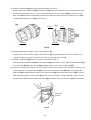
(4) Installation of the assembly reassembled in step (3) into Housing (A). (B) Set [35]
(a) Install the Pushing Button [39] into Housing (B) [35]. (See Fig. 14.)
(b) Install the assembly reassembled in step (3) into Housing (A) [35]. Note that the projections on the Front
Case [12] and the Motor Spacer [30] are engaged in the recesses in Housing (A) [35], and the projection
on Housing (A) [35] is engaged in the groove of the Cap [4]. (See Fig. 15.)
Fig. 14
[39]
[35]
Fig. 15
Projections
[35]
Groove
Projection
Recesses
(c) Set the assembly reassembled in step (b) to Housing (B) [35] and secure it with the eight Tapping Screws
(W/Flange) D3 x 16 (Black) [32].
(d) Verify proper operation of the Cap [4].
When the assembly procedure up to step (c) is completed, ensure that the number "1" on the Cap [4] and
the impact mark " " are in alignment with the triangle mark on Housing (A). (B) Set [35]. If the Cap [4]
turns loosely, correctly reinstall the Click Spring [5] as it is improperly installed. If the number "1" on the
Cap [4] or the impact mark " " cannot reach the triangle mark on Housing (A). (B) Set [35], correctly
reinstall the Cap [4] referring to step (3) (c), as it is improperly installed.
(5) Other precautions in reassembly
(a) When the assembly procedure is completed, make sure that the turning direction of the Drill Chuck
13 VLRF-N (W/O Chuck Wrench) [2] corresponds to the position of the Pushing Button [39]. When the
Pushing Button [39] is pressed from the (R)-marked side, the Drill Chuck 13VLRF-N (W/O Chuck Wrench)
[2] should turn clockwise when viewed from the rear (opposite side of the Drill Chuck 13VLRF-N (W/O
Chuck Wrench) [2]). Also make sure that the turning speed of the Drill Chuck 13VLRF-N (W/O Chuck
Wrench) [2] switches between "HIGH" and "LOW" by switching over the Shift Knob [41]. Make sure that
the run-out of the Drill Chuck 13VLRF-N (W/O Chuck Wrench) [2] holding a 12 mm dia. test bar is below
0.8 mm at a distance of 110 mm from the chuck end.
Page is loading ...
Page is loading ...
Page is loading ...
Page is loading ...
Page is loading ...
Page is loading ...
Page is loading ...
-
 1
1
-
 2
2
-
 3
3
-
 4
4
-
 5
5
-
 6
6
-
 7
7
-
 8
8
-
 9
9
-
 10
10
-
 11
11
-
 12
12
-
 13
13
-
 14
14
-
 15
15
-
 16
16
-
 17
17
-
 18
18
-
 19
19
-
 20
20
-
 21
21
-
 22
22
-
 23
23
-
 24
24
-
 25
25
-
 26
26
-
 27
27


Ask a question and I''ll find the answer in the document
Finding information in a document is now easier with AI
Other documents
-
Hitachi D 13VB3 User manual
-
-
Hitachi DS 9DVA User manual
-
Panasonic EY6932-U1 User manual
-
Tannoy CMS 6TDC User manual
-
-
-
-
RIDGID Screwdriver User manual
-