Page is loading ...

Power source: 100-240V/AC 50/60Hz
Rated LED: 9W Max.(AC)
3.5W Max.(DC)
Charging Power:7W Max.(light off)
3W Max.(light on)
Protection:IP20,Class2
Material: Body:PC Lampshade:Glass
HF system: 5.8GHz
Battery: 7.4V / 2000mAH lithium battery
Continuous illumination time: ≥180min
(when the battery power supply)
Transmission power: <0.2mW
Time setting: 8sec to 30min (adjustable)
Detection range: 1-8m (radii.) (adjustable)
Light-control: 10-2000LUX(adjustable)
Detection angle: 360°
Luminous flux: 340lm (AC) 330lm (DC) (warm white)
570lm (AC) 490lm (DC) (cold white)
Installation height: 2.5-3.5m (ceiling mount)
Working Temperature:-20~+55
LED quantity: 36PCS
LED specifications: FM-2835WNS
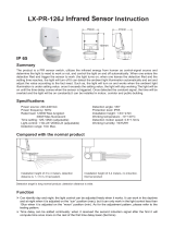
Summary
LX-MV-122LED-D Microwave Sensor Lamp Instruction
Specifications
Name of each part
IP 20
Microwave Sensor Lamp
1X
Instruction
1X
3X
3X
Quantity
Packing list in
Φ6 Plastic Expansion
3x30 Screw
White frosted glass chimney
Unscrew
Lamps and lanterns base
Use high quality White frosted glass chimney.Strengthen the
flexible refraction of light.And its function of anti-ultraviolet
makes the shade not easy to turn yellow and be broken.
100mm
280mm
This is a newly designed intelligent ceiling mount Microwave sensor LED lamp,
with the extra function of power supply in emergency. The lighting is
auto-managed by AC direct power or battery backup, that is, when power failure,
the battery backup will be responsible for the power supply of 3.5 watt. When light
on, the luminous flux will be more than 330 lm, equivalent to that of 60 watt
incandescent lamp(≈400lm).The battery backup can continuously supply power
for more than 3 hours or even more in the sensor energy-saving mode. It is widely
applied in the corridor, washing room, elevator lobby etc.
This product is designed with two configurations: one is the sensor lamp with the
function of supplying power in emergency and the other one is the intelligent
sensor lamp without the emergency function. You can make purchase according
to the practical need. But in most cases, it is necessary and wise to choose the
former one, for that the occasional power outage will cause trouble, or even
danger.
Microwave sensor
Threading hole
Switch
Mounting holes
Mounting holes
Mounting holes
Knob

Sensor information
Sensing distance adjustment range Sensing angle adjustment rangeHeight of installation2.5~3.5M
2.5-3.5m
Min:1m Min:1m
Max:8m
Max:8m
360º
1 2 3 1 2 3
安全出口
EXIT
安全出口
EXIT
In case of sudden blackout, our products can still work properly
In case of sudden blackout and there is nobody in the surrounding After the blackout, people evacuate from the elevator
Spectrogram
* Installed in the elevator, when power fails, it still supports lighting for the trapped.
LX-MV-122LED-D (AC 340lm) (warm white)
When light on, the luminous flux will be more than 330 lm,
equivalent to that of 60 watt incandescent lamp(≈400lm).
LX-MV-122LED-D (DC 330lm) (warm white)
LX-MV-122LED-D (AC 570lm) (cold white) LX-MV-122LED-D (DC 490lm) (cold white)
60 watt incandescent lamp(≈400lm)

Fig.1
Switch
Detection range setting (sensitivity)
Detection range is the term used to describe the radii of the more or less circular
detection zone produced on the ground after mounting the sensor light at a height of
2.5m, turn the detection range control fully anti-clockwise to select minimum detection
range(approx.1m radii), and fully clockwise to select maximum detection range(approx.
8m radii).
NOTE: the above detection range is gained in the case of a person who is between 1.6m~1.7m
tall with middle figure and moves at a speed of 1.0~1.5m/sec. if person’s stature, figure and
moving speed change, the detection range will also change.
In different cases, the sensitivity of the lights has certain deviation.
Function
Fig.2 Fig.3
The proper use of sensitivity potentiometer: as the photograph show, the knob is specialized
in adjusting sensitivity.when use,user can adjust the knob to the middle. Of course, in the
process of the practical usage,if you feel the sensitivity is ok ,you don't need to adjust it. If
you feel it is low,you could adjust it higher properly. Due to some environment led to wrong
action,such as car passing,wind making object fly and so on(as fig.2 fig3),so we advise
sensitivity hadn't be adjusted to the max.
The detection distance may multiply for the reflection on microwave electromagnetic field by
the metal or glass materials. Thus, lower the sensitivity to reach the appropriate detection
distance. Never turn the SENS knob to the maximum value to avoid error detection. Also the
surrounding environment will lead to error action, e.g. the automobiles passing by or the
wandering objects caused by the wind. Products should be installed more than 4 meters one
from the other, otherwise the interference among them will cause error action.
Switch
This switch is to control the battery connection. To avoid power-consumption in transit or in
storage, we preset the switch to OFF, that is, the battery is not connected. Before installation,
you should set the switch to ON to make sure that the battery is well connected to achieve the
power-supply in emergency. This LED lamp with emergency function can be used as the
common lamp, but when power failure, it will support lighting with battery automatically.

NOTE: After the light switches OFF, it takes approx. 1sec before it is able to start detecting
movement again. The light will only switch on in response to movement once this period has
elapsed.
Time setting
The light can be set to stay ON for any period of time between approx. 8sec(turn fully
anti-clockwise) and a maximum of 30min(turn fully clockwise). Any movement detected
before this time elapse will re-start the timer. It is recommended to select the shortest
time for adjusting the detection zone and for performing the walk test.
Please keep a certain distance with sensor
lamp when test,otherwise,the sensor lamp
will turn on once detect you in the detection
range.
Fig.4
LUX knob is used to adjust sensor lamp where can turn on by sensor ,in addition,we can
choose suitable location according to the needs of customer.
Light-control setting
The chosen light response threshold can be infinitely from approx. 10-2000lux. Turn it
fully anti-clockwise to select dusk- to-dawn operation at about 10 lux. Turn it fully
clockwise to select daylight operation at about 2000lux. The knob must be turned fully
clockwise when adjusting the detection zone and performing the walk test in daylight.
Installation location:
Due to the existence of a light transducer in sensor lamp(as fig.5), the light transducer must
keep in the location where daylight is sufficient, on the other hand,we have to avoid other
light source,otherwise,the light transducer will do a improper judgment for environment ray.
Due to the needs of different customers,such as installation location,lux and so on ,the
location of potentiometer knob is different.when used, it maybe require you to adjust many
times in order to meet with your needs.
It is mainly for the adjustment of the delay time from the moment the signal detected and light
auto-on till the light auto-off. You can define the delay time to your practical need. But you’d
better lower the delay time for the sake of energy saving, since the microwave sensor has the
function of continuous sensing, that is, any movement detected before the delay time
elapses will re-start the timer and the light will keep on only if there is human in the detection
range.
Warning: in the process of installation test ,please far away from the sensor lamp,because
it will turn on once detect you or test staff.

Note: Please don’t adjust the three functional buttons to excess. That is because the three
functional buttons were connected to the components directly, there is a small stopper in
each of the three components, when you adjust the buttons from start to end, the excessive
turn will damage the stopper,and lead to the 360°non-stop turn around. The adjust range
limit is 270°, please do pay attention to this.
Change the location of light transduce to the location where the daylight is visible.(as fig.6)
Fig.5 Fig.6
• Step2 Turn the knobs to the ideal conditions
(Please define the settings as per the above FUNCTION part mentioned.).
Pencil Electric drill Hammer Screwdriver
Note:Please bring the following tools.
AB
• Step1 Seperate the lamp into two parts:A and B.
Fig.7
NOTE: Chimney is fragile, please don't take too much force.
Warning!
1. Please keep it away from the children when installation.
2. Please avoid to be installed where the temperature or humidity is high.
3. Please cut off the power before installation.
Procedure of installation

• Step5 Knock the plastic expansion screw into the hole which you drill (as Fig.10)
• Step6 Put the power line through the line hole to connect on the wiring (as Fig.11)
• Step7 Fix the base of the product on the selected place with the screws (as Fig.12)
Fig.10 Fig.11
Ceiling
40mm
10mm
Fig.12
Concrete ceiling
• Step3 Put the base of the product on the ceiling to make the drilling mark (as Fig.8)
• Step4 Install the product on the place where you marked (as Fig.9)
Products should be installed more than 4 meters one from the other,
otherwise the interference among them will cause error action.
Fig.8 Fig.9
170mm
170mm
170mm
196mm
• Step8 Rotate the lampshade clockwise into the base.Installation finished. (as Fig.13)
Fig.13
L
N

Fault and the solution
Note:
the high-frequency output of this
sensor is<0.2mW- that is just one 5000 of
the transmission power of a mobile phone
or the output of a microwave oven.
Transmission power: <0.2mW
th
Induction of human movement Since entering lighting condition
Application
The load fails to work. Light-illumination is set incorrectly.Adjust the setting of the load.
Change the load.
Turn the power on.
Check the settings of the
detection area.
Re-adjust the installation place.
Check the settings of the
detection area.
Check the settings of the
detection area.
The load is broken.
The power is off.
There is a continuous signal in the region of the detection.
Moving signal is detected by the sensor (movement
behind the wall, the movement of small objects, etc.)
The lamp isn't installed well so that sensor fails to
detect reliable signals.
The motion speed is too fast or the defined detection
area is too small.
Fault Failure cause Solution
The load works all the time.
The load works when there is
no motion signal detected.
The load fails to work when
there is motion signal detected.

Warning!
●Please confirm with profession installation.
●Please cut off power supply before installation and removal operations.
●Make sure that you have cut off the power for safety purposes.
●Improper operation caused losses, the manufacturer does not undertake any responsibility.
1.The LEDS in serial can function when all the seals installed in place.
2.Please don’t remove or connect with other lamp when powered on.
3.When the LEDS in serial are damaged ,you need experienced technician to repair using
the same rating LEDS.
We are committed to promoting the product quality and reliability, however, all the electronic
components have certain probabilities to become ineffective, which will cause some troubles.
When designing, we have paid attention to redundant designs and adopted safety quota to avoid
any troubles.
This instruction, without our permission, should not be copied for any other purposes.
/