
VideoWallCalibration
User Manual

Thank you for choosing ViewSonic
With over 25 years as a world leading provider of visual solutions, ViewSonic
is dedicated to exceeding the world’s expectations for technological
evolution, innovation, and simplicity. At ViewSonic, we believe that our
products have the potential to make a positive impact in the world, and we
are confident that the ViewSonic product you have chosen will serve you
well.
Once again, thank you for choosing ViewSonic !

i
Contents
1. Required materials ..............................................................1
2. Auto Color Calibration System ..........................................1
3. Software setup .....................................................................3
4. Color Sensor Activation......................................................8
5. USB adapter cable check....................................................9
6. Performing Video Wall Color Calibration ........................10
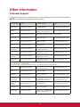
Other Information ..................................................................23
Customer Support ............................................................................23

1
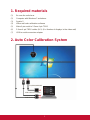
1. Required materials
(1) Be sure the units have
(2) Computer with Windows 7 and above
(3) Spyder 5
(4) Video wall color calibration software
(5) Make 9 pin serial to 2.5mm 4-pin TRRS
(6) 2.5mm 4-pin TRRS cables (N-1) (N = Number of displays in the video wall)
(7) USB to serial conversion adapter
2. Auto Color Calibration System
DV/VGA/HDMI/DP
USB to RS232 adapter
Color Sensor

2
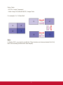
Daisy Chain
- RS232: Control Command
- Video Loop (DVI/VGA/HDMI/DP): Image Data
For example: 2 x 2 Video Wall
Note:
In display OSD, you need to enable the Tiling function and choose desired H# & V#,
then set according Position# for each display.

3
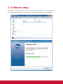
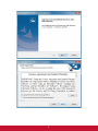
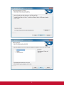
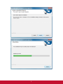
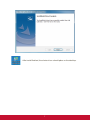
3. Software setup
Run Setup to install the Video Wall Color Calibration software for use with Spyder 5
pod. It will automatically place the shortcut icon on the desktop when complete.

4

5

6

7
After install finished, the shortcut icon should place on the desktop.

8
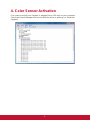
4. Color Sensor Activation
First, make sure that your Spyder5 is plugged into a USB port on your computer.
Check the Device Manager and be sure that the driver is working (i.e, Datacolor
Spyder5).

9
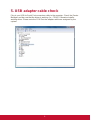
5. USB adapter cable check
Plug in your USB-to-Serial Port conversion cable to the computer. Check the Device
Manager and be sure that the driver is working (i.e., COM5). Otherwise install a
working driver. Please note the COM Port the adapter cable was assigned by the
system.

10
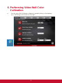
6. Performing Video Wall Color
Calibration
a. Run the video Wall Calibration software by double-clicking on the desktop
icon. It will bring up the screen on the right.

11
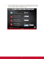
b. Click on the Warm Up button to start the 10 countdown minute timer. Select
COM port to match what was shown in the device manager for USB to serial
conversion adapter cable. Select 9600 baud rate.

12
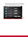
c. When the timer reaches 00:00, then click on the Color Sensor Setting button.
Place the Spyder5 pod on the central area of the video wall and click Lighting
Condition to get the ambient light reading. Click on the COM Port setting but-
ton to lock it in. Then click on the right arrow to move to the next step.

13
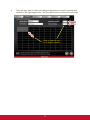
d. Drag the gray area to select your tiling configuration or select horizontal and
vertical on the right upper area. Click the right arrow to move to the next step.
Drag or select to set
H & V display number

14
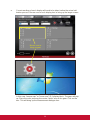
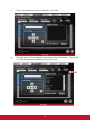
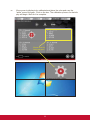
e. Current readings of each display will need to be taken before the actual cali-
bration process. Mouse over to each display box to bring up the target screen.
Mouse over to
bring up gear
In this case “mouse over” or “hover over” ID:1 display block. The gear will pop
up. Place the color pod over the center “white” area in the gear. Click on the
box. This will bring up the Measurement dialogue box.

15
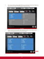
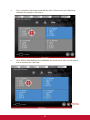
f. Click on the Measure button to collect the color data
g. The data taken will be displayed in the Measure Results window. Click on the
“x” of the Measurement dialogue box to close it out.

16
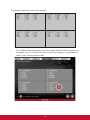
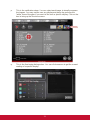
h. The screen that was measured will show up as blue as shown here. Repeat e.
thru g. for each screen until all screens show up as blue.
i. All the screens show up with a blue background when all the data is taken.
Click on the right arrow to move to the next step.

17
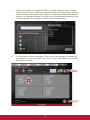
The measure data also show on the display.
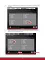
j. The software will automatically select the display with the lowest luminance as
the target. You can choose any other screen for the target x,y coordinates to
match up by clicking on the screen.
Page is loading ...
Page is loading ...
Page is loading ...
Page is loading ...
Page is loading ...
Page is loading ...
Page is loading ...
-
 1
1
-
 2
2
-
 3
3
-
 4
4
-
 5
5
-
 6
6
-
 7
7
-
 8
8
-
 9
9
-
 10
10
-
 11
11
-
 12
12
-
 13
13
-
 14
14
-
 15
15
-
 16
16
-
 17
17
-
 18
18
-
 19
19
-
 20
20
-
 21
21
-
 22
22
-
 23
23
-
 24
24
-
 25
25
-
 26
26
-
 27
27


Ask a question and I''ll find the answer in the document
Finding information in a document is now easier with AI
Related papers
-
ViewSonic NMP580-W Quick start guide
-
ViewSonic PS750W-S User guide
-
ViewSonic NMP-302w User guide
-
-
-
-
-
ViewSonic IFP8650-S User guide
-
-