Chatsworth Products 1014-IND Installation guide
- Type
- Installation guide

Installation Guide / Guía de instalación
for Oberon Model 1014-00-IND
para Modelo Oberon 1014-00-IND
"Oberon" and all other marks where denoted are trademarks of Oberon Inc. ©1999-2021 Oberon Incorporated. All rights reserved.
"Oberon" y todas las demás marcas donde se denotan son marcas comerciales de Oberon Inc. ©1999-2021 Oberon Incorporated. Todos los derechos reserve.
EPN 4547 - Rev1 - 11/2/2022
Instructions are for typical install conditions. Instructions may not be
correct for all installations due to building design, construction ma-
terials or methods used and/or building or site conditions. Consult a
contractor or architect for recommendations. For product questions
call (+1) 877-867-2312.
Las instrucciones son para condiciones típicas de instalación. Las
instrucciones pueden no ser correctas para todas las instalaciones
según el diseño del edificio, materiales de construcción o métodos
utilizados, o condiciones del edificio o del lugar. Consulte a un con-
tratista o arquitecto para obtener recomendaciones. Si tiene
preguntas con respecto al producto, llame al (+1) 877-867-2312.
Thank you for choosing Oberon. / Gracias por elegir Oberon.
WARNING / ADVERTENCIA
Follow manufacturer's instructions for hand or power tools.
Always use safety glasses. Failure to do so may result in inju-
ry and/or product damage.
Siga las instrucciones del fabricante para herramientas manu-
ales o eléctricas. Utilice siempre gafas de seguridad. Si no lo
hace, podría producirse lesiones y / o daños al producto.
WARNING / ADVERTENCIA
Use caution when working at elevated heights. Follow manu-
facturer's instructions for ladders and/or scaffolding. Failure to
do so may result in injury or death.
Tenga cuidado al trabajar a alturas elevadas y alrededor de las
aberturas de la unidad. Siga las instrucciones del fabricante
para escaleras y / o andamios. Si no lo hace, podría causar
lesiones o la muerte.
Important Information for Model 1014-00-IND / Información importante para el modelo 1014-00-IND
1. Always consider potential hazards to others around you.
2. During installation, use warning signs, etc.
3. Be sure to securely fasten the enclosure to prevent it from becoming dislodged.
1. Considere siempre el peligro potencial para quienes lo rodean.
2. Durante la instalación, utilice las señales de advertencia y demás señales.
3. Asegúrese de sujetar firmemente el gabinete para evitar que se desprenda.
Important code and installation information. / Información im-
portante sobre normas e instalación.
Read guide from beginning to end before beginning installation.
Read all warnings and cautions before beginning unit installa-
tion. Check with your local building code official to identify and
confirm compliance with local building code requirements. This
installation guide covers installing your Model 1014 in a typical
environment. The appropriate method for your installation may
vary based on building design, application, and industry practic-
es.
Lea la guía de principio a fin antes de comenzar la instalación.
Lea todas las advertencias y precauciones antes de comenzar la
instalación de la unidad. Verifique con un oficial de código
edilicio de su localidad para identificar y confirmar el cumpli-
miento con los requisitos locales del código de edificación. Esta
guía de instalación cubre la instalación del Modelo 1020 en un
entorno adecuado. El método apropiado para la instalación
puede variar según el diseño del edificio, la aplicación y las
prácticas de la industria.
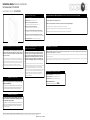
Parts Included / Partes Incluidas
(1) Enclosure / Recinto
(1) T-Bar Bracket / Soporte de barra en T
(4) M4 x 20 mm Captive Phillips Lid Screws /
Tornillos de tapa Phillips cautivos M4 x 20 mm
(4) M4 x 20 mm Captive Torx Lid Screws /
Tornillos de tapa Torx cautivos M4 x 20 mm
(4) #6 x 5/16” Pan Head Thread-Forming Screws for Plastic /
Tornillos #6 x 5/16" con cabeza plana y rosca para plástico
(4) #6 x 5/16” Flat Head Thread-Forming Screws for Plastic /
Tornillos #6 x 5/16" de cabeza plana para roscar para plástico
(4) Cushioning Washers / Arandelas de amortiguación
1) When installed in enclosure, operating temperature range of the Access Point should be de-rated (lowered) by the amount shown in the specification sheet
2) Cable ingress/egress openings in enclosures must be properly sealed to preserve NEMA 1,2, and 12 ratings. If cable openings are not sealed water-tight,
the enclosure is no longer a NEMA 1,2, or 12 enclosure
1) Cuando se instala en un gabinete, el rango de temperatura de operación del punto de acceso debe reducirse (reducirse) en la cantidad que se muestra en
la hoja de especificaciones
2) Las aberturas de entrada / salida de cables en recintos deben sellarse adecuadamente para preservar la clasificación NEMA 1,2 y 12. Si las aberturas del
cable no están selladas a prueba de agua, el gabinete ya no es un gabinete NEMA 1,2 o 12.
Important Note / Nota Importante
Tools Needed / Herramientas necesarias
Phillips Head Screwdriver / Destornillador Phillips
Torx T20 Screwdriver / Destornillador Torx T20
Screw Gun or Drill / Pistola de tornillo o taladro
Estimated Installation Time:
Tiempo Estimado de Instalación: 20m

Installation Guide / Guía de instalación
for Oberon Model 1014-00-IND
para Modelo Oberon 1014-00-IND
"Oberon" and all other marks where denoted are trademarks of Oberon Inc. ©1999-2021 Oberon Incorporated. All rights reserved.
"Oberon" y todas las demás marcas donde se denotan son marcas comerciales de Oberon Inc. ©1999-2021 Oberon Incorporated. Todos los derechos reserve.
EPN 4547 - Rev1 - 11/2/2022
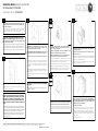
Choose an appropriate location for data and power ingress. Drill an appro-
priately sized hole into the enclosure to fit the selected conduit size. Fasten
the conduit to the drilled hole.
Elija una ubicación adecuada para el ingreso de datos y energía. Taladre un
orificio del tamaño apropiado en el gabinete para que se ajuste al tamaño
del conducto seleccionado. Fije el conducto al orificio perforado.
1
(Optional) Install a surface mount biscuit jack, if desired, for cable connec-
tivity.
(Opcional) Instale un conector de galletas de montaje en superficie, si lo
desea, para la conectividad del cable.
2
The 1014 enclosure can also be mounted to a surface using screws
penetrating the box. Before installing the access point, drill 1/4” holes
through the box in four (4) corners. Use (4) #10 x 2” screws (not includ-
ed) and suitable anchor hardware (not included).
(For installations that require cushioning washers) Insert a cushion-
ing washer between each corner of the enclosure and the wall or sur-
face.
Tighten the screws uniformly around the enclosure so that it does not
flex.
El gabinete 1014 también se puede montar en una superficie utilizando
tornillos que penetran en la caja. Antes de instalar el punto de acceso,
taladre agujeros de 1/4” a través de la caja en cuatro (4) esquinas. Use
(4) tornillos #10 x 2” (no incluidos) y herrajes de anclaje adecuados (no
incluidos).
(Para instalaciones que requieren arandelas de amortiguación) In-
serte una arandela de amortiguación entre cada esquina del gabinete y
la pared o superficie.
Apriete los tornillos de manera uniforme alrededor del gabinete para que
no se doble.
3
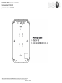
To mount the Cisco AIR-BRACKET-1 or -2, align the bracket’s four (4)
“A” marked holes with the four (4) embosses on the enclosure base
labeled “A” on the mounting legend.
If installing the AIR-BRACKET-1, use the four (4) provided #6 x 5/16” flat
head screws to fasten the bracket to the enclosure base.
If installing the AIR-BRACKET-2, use the four (4) provided #6 x 5/16”
pan head screws to fasten the bracket to the enclosure base.
Para montar Cisco AIR-BRACKET-1 o -2, alinee los cuatro (4) agujeros
marcados con "A" del soporte con los cuatro (4) relieves en la base del
gabinete etiquetados como "A" en la leyenda de montaje.
Si instala el AIR-BRACKET-1, use los cuatro (4) tornillos #6 x 5/16” de
cabeza plana provistos para fijar el soporte a la base del gabinete.
Si instala el AIR-BRACKET-2, use los cuatro (4) tornillos #6 x 5/16” de
cabeza plana provistos para fijar el soporte a la base del gabinete.
4a
Fasten the T-Bar Bracket directly to the enclosure using two (2) of the
provided #6 x 5/16" pan head screws. The bracket can be mounted to
the enclosure in either the vertical or horizontal position, as desired.
Sujete el soporte de la barra en T directamente al gabinete utilizando
dos (2) de los tornillos de cabeza plana #6 x 5/16" provistos. El soporte
se puede montar en el gabinete en posición vertical u horizontal, según
lo desee.
4b
***NOTE: If the wall or surface to which the enclosure is at-
tached is not completely smooth and flat, it is recommended
that the cushioning washers be placed between the mounting
tabs and the wall or surface. The cushioning washers will re-
duce flexing by the enclosure when tightened against an une-
ven surface, which can cause the seal between the lid and box
to open.
***NOTA: Si la pared o superficie a la que se adjunta el gabi-
nete no es completamente lisa y plana, se recomienda colocar
las arandelas de amortiguación entre las pestañas de montaje
y la pared o superficie. Las arandelas de amortiguación re-
ducirán la flexión del gabinete cuando se aprietan contra una
superficie irregular, lo que puede hacer que se abra el sello
entre la tapa y la caja.
Cisco
Aruba
Other
***NOTE: If the conduit hole was drilled into the back of the
enclosure, prior to starting steps 3a or 3b, route the data and
power cables into the enclosure prior to mounting. Properly seal the
hole to maintain water tightness.
***NOTA: Si el orificio del conducto se perforó en la parte pos-
terior del gabinete, antes de comenzar los pasos 3a o 3b, dirija
los datos y los cables de alimentación al gabinete antes del mon-
taje. Selle adecuadamente el orificio para mantener la estanquei-
dad.
***NOTE: For steps 4a and 4b, reference the mounting leg-
end on page 3.
***NOTA: Para los pasos 4a y 4b, consulte la leyenda de
montaje en la página 3.
After the cables are attached, place the lid on the base then secure it with
the four (4) M4 x 25mm pan head machine screws or tamper resistant Torx
screws provided with the enclosure. The screws should be tightened to 8
in-lbs to properly seal the enclosure. Do not over tighten. Make sure the
gasket is properly seated prior to tightening.
The installation is now complete.
Después de conectar los cables, coloque la tapa en la base y luego fíjela
con los cuatro (4) tornillos de cabeza plana M4 x 25 mm o tornillos Torx
resistentes a la manipulación provistos con el gabinete. Los tornillos
deben apretarse a 8 in-lb para sellar adecuadamente el gabinete. No
apriete demasiado. Asegúrese de que la junta esté asentada correctamente
antes de apretarla.
La instalación está completa.
6
5
If the conduit hole was drilled into one of the sides of the enclosure,
route the data and power cables into the enclosure. Properly seal the hole
to maintain water tightness.
Attach data and power cables to the access point, then fasten the access
point to its bracket or clip.
Si se taladró el orificio del conducto en uno de los lados del gabinete,
dirija los cables de datos y alimentación al gabinete. Selle adecuadamente
el orificio para mantener la estanqueidad.
Conecte los datos y los cables de alimentación al punto de acceso, luego
fije el punto de acceso a su soporte o clip.

Installation Guide / Guía de instalación
for Oberon Model 1014-00-IND
para Modelo Oberon 1014-00-IND
"Oberon" and all other marks where denoted are trademarks of Oberon Inc. ©1999-2021 Oberon Incorporated. All rights reserved.
"Oberon" y todas las demás marcas donde se denotan son marcas comerciales de Oberon Inc. ©1999-2021 Oberon Incorporated. Todos los derechos reserve.
EPN 4547 - Rev1 - 11/2/2022
-
 1
1
-
 2
2
-
 3
3


Chatsworth Products 1014-IND Installation guide
- Type
- Installation guide
Ask a question and I''ll find the answer in the document
Finding information in a document is now easier with AI
in other languages
Other documents
-
OBERON 39-1020-PMK Installation guide
-
BFT Oberon User manual
-
Dali OBERON 7 C Owner's manual
-
Dali Oberon User manual
-
Dali OBERON Series User manual
-
-
-
 LightPro Oberon DL 192P Post Light User manual
-
Toto CP Installation guide
-
Sound Town OBERON-112PW User manual
