Page is loading ...

m
CORPORATION
MUNCIE, INDIANA, USA
INDUSTRIAL COMBUSTION EQUIPMENT AND VALVES
Maxon practices a policy of continuous product improvement. It reserves the right to alter specifications without prior notice.
VENTITE™ Inspirators Page 3300-S-1
9/90
Installation Instructions
General
VENTITE™ Inspirators are only a part of a
complete combustion system.
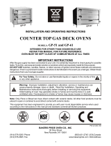
Sketch 1 below summarizes the additional
components that might typically be part of a complete
modulated system. Use this sketch and the following
comments as a check list prior to actual installation.
Alternate operating modes are illustrated below: for
manual operation, see sketch 2; for on-off
operation, see sketch 3 (solid lines); for high-low
operation, see sketch 3 (including dotted lines).
1. Electrical service must match the voltage, phase
and cycle of all electrical system components.
2. Gas supply piping must be large enough to
maintain required fuel pressures (as high as 30
PSIG depending on application) at the
inspirator’s inlet while burner is operating at full
capacity. Anything more than minimum distance
or piping turns may necessitate “oversizing”
piping runs to keep pressure drops within
acceptable ranges.
3. Clean fuel lines are essential to prevent
blockage of pipe train components and inspirator
burner gas ports. All dirt, scale and pipe dope
should be blown out of any new gas line before
actually connecting to the burner system.
4. Main shut-off cock ② should be upstream of both
main gas regulator and pilot line take-off. Use it to
shut off fuel to both pilot and main burner during
shutdown periods of more than a few hours.
5. Main gas regulator ③ is essential to maintain a
uniform system supply pressure. A separate
regulator should be provided in the branch
leading to each burner system if more than one is
served by a common main. Size regulator for full
system capacity at required pressure, including
pipe train losses. Follow the instructions attached
to the regulator for installation.
Maxon assumes no responsibility for the use or
misuse of the piping layouts shown. Specific
piping and wiring diagrams should always be
submitted to the appropriate agencies for
approval on each application.

m
CORPORATION
MUNCIE, INDIANA, USA
INDUSTRIAL COMBUSTION EQUIPMENT AND VALVES
Maxon practices a policy of continuous product improvement. It reserves the right to alter specifications without prior notice.
8. Fuel Control Valve controls burner heat
release by throttling gas flow to it. It should
include provision for an adjustable minimum and
throttling over a turndown range that matches
burner capabilities. In manual systems, it may be
an indicating cock. Maxon Control Valves are not
intended for tight shut-off.
9. Minimize pressure drop between inspirator and
burner(s). Inlet pipe leading to any burner should
be a straight run of at least four pipe diameters in
length. If the VENTITE™ Inspirator is supplying
multiple burners or multiple inlets to a single
burner element, care should be taken so that air/
gas mixing piping gives minimal pressure drop
and maximum uniformity.
Do not install any shut-off device in the air/gas
mixture line.
10. Test connections are essential for burner
adjustment. They should be provided
downstream of the main regulator and at each
burner inlet. Test connections must be plugged
except when readings are being taken.
Page 3300-S-2 VENTITE™ Inspirators
6. Pilot take-off ④ should be upstream of main gas
regulator but downstream of main gas cock. It
should normally include its own pilot gas
regulator, a solenoid valve and a shut-off cock.
An adjustable orifice gas cock at the pilot inlet
simplifies adjustment.
Suitable pilots should be provided for the type
of burner and control system being used.
7. Fuel shut-off valve(s) ⑤ (when properly
connected to a safety control system) are
designed to shut the fuel supply off when a
hazardous operating condition is sensed. Manual
reset valves require operator attendance each
time the system is started up (or restarted after a
trip-out). Motorized shut-off valves permit
automatic start-restart when used with an
appropriate control system.
Installation Instructions

m
CORPORATION
MUNCIE, INDIANA, USA
INDUSTRIAL COMBUSTION EQUIPMENT AND VALVES
Maxon practices a policy of continuous product improvement. It reserves the right to alter specifications without prior notice.
VENTITE™ Inspirators Page 3300-S-3
Start-up Instructions
9/90
Before proceeding, verify that all equipment has
been installed in accordance with the general
instructions found in the preceding pages.
Initial adjustment and light-off should be
undertaken only by trained and experienced
personnel familiar with combustion systems,
control/safety circuitry and overall installation.
If Maxon instructions conflict with local codes
or regulations, contact Maxon before start-up.
For initial system start-up:
1. Disconnect control motor from flow control
valve (if applicable). Initial start-up should only be
accomplished during a “manual” burner control
mode.
2. Purge furnace or oven. Furnace doors, vents
and flues should all be wide open and the
purging allowed to continue until all possible
accumulation of explosive vapors is dispersed.
Twenty minutes or more may be necessary on
large installations.
CAUTION: Do not by-pass control panel timers
typically controlling sequential operations.
3. Bleed air out of gas line leading to main gas
cock, taking care not to allow accumulation of
flammable vapors.
4. Open main and pilot gas cocks and light pilots
following instructions appropriate for the burner
and pilot type. If multiple pilots are used, open
individual cocks and adjust each in turn.
5. Install manometer to read mixture pressure at
burner and to establish required minimum. With
pilots burning, open fuel shut-off valve(s) and
advance fuel control valve slowly from minimum
setting until ignition of main flame occurs.
Refine main gas regulator setting, if necessary,
and verify control valve setting which gives
required minimum mixture pressure. Adjust
minimum stop of control valves as needed (if
applicable).
6. Advance control valve (or indicating firing cock)
manually to high fire position (adjusting if
necessary), observing burner performance.
CAUTION: If burners go out, close shut-off
valve or shut main gas cock at once. Return to
minimum setting, re-light pilots if necessary,
then turn main gas on again. Check carefully
that every burner nozzle is lit before
proceeding.
7. Adjust inspirator air shutter opening (if
necessary) to obtain desired flame character.
Shutter will normally be wide open if spud orifice
has been correctly sized.
8. Cycle system off and re-light several times.
When burner performance is satisfactory and
stable throughout the firing range, reconnect
control valve linkage to control motor.
Control linkage travel must be such that control
valve is moved throughout its complete travel, or
cataloged capacities and turndowns will not be
achieved.
If less than full-rated burner capacity is
required, linkage can be adjusted to limit
maximum output. With interrupted pilot, it may
be necessary to set control for somewhat higher
than minimum burner setting to permit hold-in of
flame detection system without pilot.
CAUTION: Internal drive mechanism within the
control motor may be damaged if linkage is
adjusted so as to cause binding.
9. Re-check differential gas pressure with unit at
operating temperature. Refine “high fire” setting if
necessary, considering differential pressure,
flame length, and appearance. Dust or
contaminants in the air stream may affect flame
appearance.
10. Plug all test connections not in use to avoid
dangerous fuel leakage. Replace equipment
cover caps and tighten linkage screws.
11. Check out overall system operation by cycling
through light-off at minimum, interrupting pilot,
and allowing temperature control system to cycle
burner from minimum to maximum and return.
Re-check all safety system interlocks for
proper setting and operation.
WARNING: Test every UV installation for
dangerous spark excitation from ignitors and
other possible sources of direct or reflected UV
radiation. Use only gas-tight scanner
connections.
12. Before system is placed into full service,
instruct operator personnel on proper start-up,
operation, and shut-down of system. Establish
written instructions for their future reference.

m
CORPORATION
MUNCIE, INDIANA, USA
INDUSTRIAL COMBUSTION EQUIPMENT AND VALVES
Maxon practices a policy of continuous product improvement. It reserves the right to alter specifications without prior notice.
Page 3300-S-4 VENTITE™ Inspirators
Start-Up Instructions
For Low Pressure Gas Hand Torches
To start-up:
1. Open air valve to the desired degree.
2. With an ignition source at the hand torch nozzle,
open gas valve until flame is established.
3. Adjust gas valve for the desired flame with sharp
well-defined structure. A flame with long weak
structure indicates a rich mixture and too much
gas. A short light flame with hissing noise
indicates a lean mixture with too little gas.
4. If higher or lower heat release is desired, re-
adjust air valve first, then refine gas valve setting.
To shut-down, close the gas valve first, then the air
valve.
CAUTION: Always observe good judgement
and common sense when operating a portable
hand torch.
Maintenance Instructions
The Venturi tube and air shutter of the VENTITE™
Inspirator should be kept clean to assure normal
operation.
Burner nozzles should be regularly inspected for
possible deterioration and replaced if necessary.
Generally, the higher the operating temperature, the
more frequent the inspections should be.
/