Page is loading ...

1
Owner’s Manual
External Battery Cabinet
for Use with 3-Phase 208V SUT UPS Systems and
RBCSUT Replacement Battery Cartridges
Model: BP288VEBPNB
(Series Number: AG-01A2)
Español 13 • Français 25
1111 W. 35th Street, Chicago, IL 60609 USA • www.tripplite.com/support
Copyright © 2018 Tripp Lite. All rights reserved.

2
1. Important Safety Warnings
SAVE THESE INSTRUCTIONS
All sections of this manual contain instructions and warnings that must be followed during the installation and operation of
the battery cabinet described in this manual. Read ALL instructions thoroughly before attempting to move, install or connect
your battery cabinet. Failure to heed these warnings may affect your warranty and cause serious property damage and/or
personal injury.
DANGER! LETHAL HIGH VOLTAGE HAZARD!
All wiring should be performed by a qualified electrician, in accordance with the warnings in this manual and all
applicable electrical and safety codes. Incorrect wiring may cause serious personal injury and property damage.
Installation and Location Warnings
• Install the battery cabinet in a controlled indoor environment, away from moisture, temperature extremes, flammable liquids and gasses,
conductive contaminants, dust and direct sunlight.
• Install the battery cabinet in a level, structurally sound location.
• The battery cabinet is very heavy; use extreme caution when moving or lifting the unit.
• Operate the battery cabinet at indoor temperatures between 32° F and 104° F (0° C and 40° C) and 30-90% non-condensing humidity
only. For optimum battery performance, maintain an ambient indoor temperature of 77° F (25° C).
• Leave adequate space around the front and rear of the battery cabinet for proper ventilation. Do not block, cover or insert objects into the
external ventilation openings of the battery cabinet.
• Do not place any object on the battery cabinet, especially containers of liquid.
• Do not attempt to stack the battery cabinet. Attempting to stack the battery cabinet may cause permanent damage and create a potential
for serious personal injury.
• Do not attempt to unpack or move the battery cabinet without assistance. Use appropriate handling equipment rated to bear the weight
and bulk of the battery cabinet, such as freight elevators, pallet jacks and forklifts. (Fully extend forks under load. Spread forks to
maximum possible width under load. Lift cabinet from bottom only. Wear safety shoes.)
• For emergency use, install a fire extinguisher rated for energized electrical equipment fires (Class C rating or exact equivalent, with a non-
conductive extinguishing agent) near the battery cabinet.
Connection Warnings
• When connected, the battery cabinet contains hazardous high voltages that have the potential to cause personal injury or death from
electric shock.
• With batteries installed, the battery cabinet has its own energy source. The output terminals may be live even when the battery cabinet is
not connected to a UPS system.
• The battery cabinet must be suitably grounded according to all applicable electrical wiring regulations.
• Use of this equipment in life support applications where failure of this equipment can reasonably be expected to cause the failure of the
life support equipment or to significantly affect its safety or effectiveness is not recommended.
• De-energize all input and output power sources before installing cables or making electrical connections.
• Use flexible cable of sufficient length to permit battery cabinet servicing.
• Use ferrule caps to cover termination cables and prevent frayed ends from shorting on terminal blocks. Use cabling rated VW-1, FT-1 or
better. Use cable sleeves and connector clamps.
• Confirm that all cables are marked correctly according to their purpose, polarity and diameter.
• Observe proper polarity by following the positive and negative markings on the unit. Failure to observe proper polarity may damage the
batteries and create a serious risk of personal injury and property damage.
• Wiring should be performed by trained, qualified electricians only.

3
1. Important Safety Warnings
Battery Warnings
• The battery cabinet does not require routine maintenance by the user. There are no user-serviceable parts inside. Only qualified,
knowledgeable service personnel familiar with all required precautions should open the access panels for any reason. Keep unauthorized
personnel away from batteries.
• Valve-regulated recombinant lead-acid (VRLA) batteries can contain an explosive mixture of hydrogen gas. DO NOT SMOKE when near
batteries. DO NOT cause flames or sparks near batteries. Discharge static electricity from body before touching batteries. DO NOT open or
mutilate batteries—released electrolyte is harmful to the skin and eyes and may be toxic. DO NOT dispose of batteries in a fire—they may
explode.
• Batteries present a risk of electrical shock and burns from high short-circuit current. Battery connection or replacement should be
performed only by qualified service personnel, observing proper precautions. Use tools with insulated handles. Remove watches,
rings or other metal objects. Wear rubber gloves and boots. Do not short or bridge the battery terminals with any object. Do not lay tools
or metal parts on top of batteries. Use tools with insulated handles. There are no user-serviceable parts inside the battery cabinet. Battery
replacement should be performed only by authorized service personnel using the same number and type of batteries (Sealed Lead-Acid).
The batteries are recyclable. Refer to your local codes for disposal requirements or visit http://www.tripplite.com/support/recycling-program
for recycling information. Tripp Lite offers a complete line of UPS System Replacement Battery Cartridges (R.B.C.). Visit Tripp Lite on the
Web at http://www.tripplite.com/products/battery-finder/ to locate the specific replacement battery for your UPS.
• Replace batteries with equivalent batteries (same number and type) available from Tripp Lite.
• Fuse replacement should only be performed by qualified service personnel. Replace with only the same type and rating: 63A 660V.
• The batteries are recyclable. Refer to local codes for disposal requirements. Do not dispose of batteries except through approved channels
in accordance with all applicable local, state and national regulations.
• Do not connect or disconnect batteries when the UPS system is operating from the battery supply or when the unit is not in bypass mode.
Disconnect the charging source prior to connection or disconnecting battery terminals.
• If the charging source remains off for an extended period of time, it should be turned on periodically to allow the batteries to recharge. The
charging source should be turned on and the batteries should be recharged at least one uninterrupted 24-hour period every 3 months.
Failure to recharge the batteries periodically may cause permanent battery damage.
• Allow batteries to charge uninterrupted for 24 hours after installation.

4
2. Installation and Setup
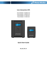
2.1 Rear Panel View
Note: Inspect the unit before performing installation. Make sure nothing inside the package is damaged. Keep the original packaging for future use.
A
Battery Terminal Blocks with Fast-Acting Fuses
B
DC Breaker:
• Battery over-current protection breaker.
• When servicing internal batteries, place the position of the breaker in the “O” position. This breaker does not interrupt DC power flow
between the UPS and any additional battery packs connected in parallel to the UPS. In the event a second battery pack is connected
to the battery bank, the DC voltage from the UPS Bat.+/- will flow through without any interruption to the second battery bank.
Note: The DC breaker is tripped (set to off, or the “O” position) at the factory. Do not flip the breaker’s actuator level to the on (“I”) position until the
battery pack has been successfully installed and properly connected to the UPS.
C
Input/Output Terminal Blocks: Connects to UPS and additional external battery cabinets.
D
Ground Terminal: Connects to earth ground.
E
Cable Access Ports
2.2 Battery Cabinet Installation and Setup
Unpacking and Inspection
1. Remove the battery cabinet from the packaging.
Note: The battery cabinet is heavy. Be cautious when unpacking and lifting the unit to avoid injury.
2. Inspect the package contents for impact or other damage:
• Battery Cabinet
• Battery Cartridge Kit (x24)
• Owner’s Manual
B
CC
D
A
E

5
2. Installation and Setup
Selecting Installation Site
To minimize the possibility of damage to the battery bank and extend the life of the batteries, follow the instructions below:
1. Maintain at least 8 inches (20 cm) clearance between the unit’s rear panel and a wall (or other obstructions).
2. Do not block airflow to the unit’s ventilation openings.
3. Ensure the installation site environmental conditions are in accordance with the unit’s working specifications to avoid overheating and/or
excessive moisture.
4. Do not place the unit in a dusty or corrosive environment or near any flammable objects.
5. This unit is not designed for outdoor use.
Battery Cabinet Placement
Use the casters to move the battery cabinet for a short distance over a level, smooth, stable surface by pushing it from the front or rear (not
the side panels). Do not attempt to roll the unit over long distances. The battery cabinet should be moved close to its installation location
inside its shipping container before it is unpacked. (Use a forklift or pallet jack to move the shipping container.)
WARNING: Do not push or pull the battery cabinet by the side panels.
Leveling
1
After the battery cabinet has been moved to the installation location, use a
carpenter’s level to check the slope of the floor. If the floor slopes more than
1%, choose an alternate installation site.
2
Use an 18 mm open-end wrench to lower each leveler until it reaches the floor.
Make sure each leveler is in firm contact with the floor.
Note: Lower a leveler by turning it clockwise; raise a leveler by turning it counter-
clockwise
3
After lowering each leveler, use the carpenter’s level to confirm the enclosure
is level in all directions. Adjust the levelers as required until the battery pack is
level.
4
(Optional) To provide an additional measure of stability, you can use the
shipping brackets that secured the unit to the shipping pallet to secure
mounting points in the floor using user-supplied hardware or Tripp Lite’s
SmartRack Bolt-Down Kit (Part # SR331).
1
2
3
4

6
2. Installation and Setup
Assembling Battery Cartridges
If supplying your own batteries, use the Battery Cartridge Kits included with this battery cabinet to create 24 battery cartridge strings.
Use only 12V 9A sealed valve-regulated lead acid batteries (VRLA) with F1-type terminals. Tripp Lite recommends using
the same battery/battery type used in your UPS.
There are 24 battery cartridge kits that include the following parts:
x1 x3 x1 x3
1
Place batteries in the battery tray. Lift the battery tray lid so the
battery terminals are exposed.
1

7
2. Installation and Setup
2
3
4
2
Use the large cable harness to connect the negative (-) terminal in
the last battery in the string
A
and the positive (+) terminal on
the first battery in the string
B
.
3
Use the three short battery cables to connect the negative (-)
terminals to the positive (+) terminals
A
.
4
Once all batteries are connected, close the battery tray lid and
secure with the included adhesive tape.
5
Repeat steps 1 through 4 for each additional battery cartridge
assembly (24 total).
B
A
A
A
A

8
Installing Battery Cartridges
Notes:
•
The following battery replacement instructions are for the included Battery Cartridge Kit assemblies and Tripp Lite RBCSUT Replacement Battery Cartridges.
• For more information on the battery cabinet’s electrical circuitry, refer to Battery Cabinet Wiring Diagram
1
Make sure the DC breaker is tripped (set to off, or the “O” position).
2
Open the battery cabinet’s front door.
3
Remove the screws securing the wiring brackets. Remove brackets.
4
Insert the battery cartridge into the slot, making sure the battery
cartridge terminals are facing outward. Repeat for each additional
battery cartridge (24 total).
5
Use the screws from step 3 to reattach the wiring brackets.
2. Installation and Setup
3
6
Open the terminal housings and connect the battery cartridge
terminals
6A
. Refer to
6B
for the entire battery installation.
Important! Make sure all cables labeled with a +, -, or N
are correctly connected to their corresponding connector.
Improper connection can result in damage to battery cabinet
and/or UPS system. Please refer to the white labels attached
to the cables and the labels on the terminal housings for
proper connection.
7
Once all connectors are attached, close the terminal housings and
proceed to Connecting a UPS to the Battery Cabinet.
1. Connect the N1, N2, N3 and N4 cables in the center.
2. Connect the -1, -2, -3 and -4 cables on the left.
3. Connect the +1, +2, +3 and +4 cables on the right.
–1
through
–4
N1
through
N4
+1
through
+4
6B
6A

9
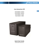
Connecting a UPS to the Battery Cabinet
The external battery cabinet will increase the battery runtime. As a result, recharge time will also increase. Follow the installation diagram
below to connect the battery cabinet to the UPS. For information on connecting to the UPS terminal block, refer to sections 3.6.2 and 3.7
of the SUT UPS Owner’s Manual.
UPS System
SUT20K SUT30K SUT40K SUT60K
Battery Input Cable*
1 AWG (35 mm
2
) 1/0 AWG (50 mm
2
) 3/0 AWG (95 mm
2
) 250 kcmil (120 mm
2
)
* Use copper wire rated to 194°F (90°C) or higher. If using cable designed for a lower temperature capacity, please size wire according to local regulations.
2. Installation and Setup
+ + ––N N
TO ADDITIONAL
EXTERNAL BATTERY
CABINET (NO WIRE
CONNECTION
OTHERWISE)
TO UPS
Notes:
• The DC breaker is tripped (set to off, or the “O” position) at the factory. Do not flip the breaker’s actuator lever to the on (“I”) position until the battery
cabinet has been properly connected to the UPS.
• Always use compression lugs with cabling to connect the UPS to the battery cabinet’s terminal block.
• Installer should determine correct wire type based on application.

11
3. Battery Replacement
1
Make sure the DC breaker is tripped (set to off, or the “O” position).
2
Open the battery cabinet’s front door.
3
Open the terminal housings covering the internal battery cable
terminals. Disconnect the terminals
3A
. Refer to
3B
for the entire
battery installation.
1. Disconnect the +1, +2, +3 and +4 cables on the right.
2. Disconnect the -1, -2, -3 and -4 cables on the left.
3. Disconnect the N1, N2, N3 and N4 cables in the center.
–1
through
–4
N1
through
N4
+1
through
+4
4
4
Remove the screws securing the wiring brackets. Remove
brackets.
5
Carefully remove each used battery cartridge by pulling it out by its
tab. Insert the new battery cartridge into the slot.
6
Use the screws from step 4 to reattach the wiring brackets.
7
In the reverse order of step 3 (4,3,2,1), reconnect the battery
terminals. Refer to Figure 3-2 for the entire battery installation.
Important! Make sure all cables labeled with a +, -, or N
are correctly connected to their corresponding connector.
Improper connection can result in damage to battery pack
and/or UPS system. Please refer to the white labels attached
to the cables and the labels on the terminal housings for
proper connection.
Once all connectors are attached, close the terminal housings.
8
Set the DC breaker to the on (“I”) position to resume normal
operation.
Note: The following battery replacement instructions are for Tripp Lite RBCSUT Replacement Battery Cartridges.
3A
3B

12
4. UPS and Battery Recycling
Batteries can present a risk of electrical shock and burn from high short-circuit current. Observe proper precautions. Do not dispose of the
batteries in a fire. Do not open the batteries. Do not short or bridge the battery terminals with any object. Unplug and turn off the UPS before
performing battery replacement. Use tools with insulated handles. Battery replacement should be performed only by authorized service
personnel using the same number and type of batteries (Sealed Lead-Acid). The batteries are recyclable. Refer to your local codes for
disposal requirements or visit http://www.tripplite.com/support/recycling-program for recycling information.
5. Storage and Service
Storage
If the charging source remains off for an extended period of time, it should be turned on periodically to allow the batteries to recharge. The
charging source should be turned on and the batteries should be recharged for at least one uninterrupted 24-hour period every 3 months.
Failure to recharge the batteries periodically may cause permanent battery damage.
Service
Your Tripp Lite product is covered by the warranty described in this manual. A variety of Extended Warranty and On-Site Service Programs
are also available from Tripp Lite. For more information on service, visit www.tripplite.com/support. Before returning your product for service,
follow these steps:
1. Review the installation and operation procedures in this manual to insure that the service problem does not originate from a misreading
of the instructions.
2. If the problem continues, do not contact or return the product to the dealer. Instead, visit www.tripplite.com/support.
3.
If the problem requires service, visit www.tripplite.com/support and click the Product Returns link. From here you can request a Returned
Material Authorization (RMA) number, which is required for service. This simple on-line form will ask for your unit’s model and serial
numbers, along with other general purchaser information. The RMA number, along with shipping instructions will be emailed to you. Any
damages (direct, indirect, special or consequential) to the product incurred during shipment to Tripp Lite or an authorized Tripp Lite service
center are not covered under warranty. Products shipped to Tripp Lite or an authorized Tripp Lite service center must have transportation
charges prepaid. Mark the RMA number on the outside of the package. If the product is within its warranty period, enclose a copy of your
sales receipt. Return the product for service using an insured carrier to the address given to you when you request the RMA.
6. Warranty
1-YEAR LIMITED WARRANTY
Seller warrants this product, if used in accordance with all applicable instructions, to be free
from original defects in material and workmanship for a period of one (1) year from the date
of initial purchase. If the product should prove defective in material or workmanship within
that period, Seller will repair or replace the product, in its sole discretion. Service under this
Warranty can only be obtained by your delivering or shipping the product (with all shipping or
delivery charges prepaid) to: Tripp Lite, 1111 W. 35th Street, Chicago, IL 60609 USA. Seller
will pay return shipping charges. Visit www.tripplite.com/support before sending any equipment
back for repair.
THIS WARRANTY DOES NOT APPLY TO NORMAL WEAR OR TO DAMAGE RESULTING FROM
ACCIDENT, MISUSE, ABUSE OR NEGLECT. SELLER MAKES NO EXPRESS WARRANTIES
OTHER THAN THE WARRANTY EXPRESSLY SET FORTH HEREIN. EXCEPT TO THE EXTENT
PROHIBITED BY APPLICABLE LAW, ALL IMPLIED WARRANTIES, INCLUDING ALL WARRANTIES
OF MERCHANTABILITY OR FITNESS, ARE LIMITED IN DURATION TO THE WARRANTY PERIOD
SET FORTH ABOVE; AND THIS WARRANTY EXPRESSLY EXCLUDES ALL INCIDENTAL AND
CONSEQUENTIAL DAMAGES. (Some states do not allow limitations on how long an implied
warranty lasts, and some states do not allow the exclusion or limitation of incidental or
consequential damages, so the above limitations or exclusions may not apply to you. This
Warranty gives you specific legal rights, and you may have other rights which vary from
jurisdiction to jurisdiction).
WARNING: The individual user should take care to determine prior to use whether this device
is suitable, adequate or safe for the use intended. Since individual applications are subject to
great variation, the manufacturer makes no representation or warranty as to the suitability or
fitness of these devices for any specific application.
Regulatory Compliance Identification Numbers
For the purpose of regulatory compliance certifications and identification, your Tripp Lite product
has been assigned a unique series number. The series number can be found on the product
nameplate label, along with all required approval markings and information. When requesting
compliance information for this product, always refer to the series number. The series number
should not be confused with the marketing name or model number of the product.
WEEE Compliance Information for Tripp Lite Customers and Recyclers
(European Union)
Under the Waste Electrical and Electronic Equipment (WEEE) Directive and
implementing regulations, when customers buy new electrical and electronic equipment
from Tripp Lite they are entitled to:
• Send old equipment for recycling on a one-for-one, like-for-like basis (this varies
depending on the country)
• Send the new equipment back for recycling when this ultimately becomes waste
Tripp Lite has a policy of continuous improvement. Specifications are subject to change without
notice.
1111 W. 35th Street, Chicago, IL 60609 USA • www.tripplite.com/support

13
Manual del Propietario
1111 W. 35th Street, Chicago, IL 60609 USA • www.tripplite.com/support
Copyright © 2018 Tripp Lite. Todos los derechos reservados.
Gabinete de Baterías Externas
Para Uso con Sistemas UPS Trifásicos SUT de 208V y
Cartuchos de Baterías de Reemplazo RBCSUT
Modelo: BP288VEBPNB
(Número de Serie: AG-01A2)
English 1 • Français 25
/