Page is loading ...

®
CUW
Intel
®
810 ATX Motherboard
USER’S MANUAL

2 ASUS CUW User’s Manual
USER'S NOTICE
Product Name: ASUS CUW
Manual Revision: 1.08 E497
Release Date: December 1999
No part of this manual, including the products and software described in it, may be repro-
duced, transmitted, transcribed, stored in a retrieval system, or translated into any language in
any form or by any means, except documentation kept by the purchaser for backup purposes,
without the express written permission of ASUSTeK COMPUTER INC. (“ASUS”).
ASUS PROVIDES THIS MANUAL “AS IS” WITHOUT WARRANTY OF ANY KIND,
EITHER EXPRESS OR IMPLIED, INCLUDING BUT NOT LIMITED TO THE IMPLIED
WARRANTIES OR CONDITIONS OF MERCHANTABILITY OR FITNESS FOR A PAR-
TICULAR PURPOSE. IN NO EVENT SHALL ASUS, ITS DIRECTORS, OFFICERS,
EMPLOYEES OR AGENTS BE LIABLE FOR ANY INDIRECT, SPECIAL, INCIDEN-
TAL, OR CONSEQUENTIAL DAMAGES (INCLUDING DAMAGES FOR LOSS OF
PROFITS, LOSS OF BUSINESS, LOSS OF USE OR DATA, INTERRUPTION OF BUSI-
NESS AND THE LIKE), EVEN IF ASUS HAS BEEN ADVISED OF THE POSSIBILITY
OF SUCH DAMAGES ARISING FROM ANY DEFECT OR ERROR IN THIS MANUAL
OR PRODUCT.
Product warranty or service will not be extended if: (1) the product is repaired, modified or
altered, unless such repair, modification of alteration is authorized in writing by ASUS; or (2)
the serial number of the product is defaced or missing.
Products and corporate names appearing in this manual may or may not be registered trade-
marks or copyrights of their respective companies, and are used only for identification or
explanation and to the owners’ benefit, without intent to infringe.
• QuickStart and JumperFree are trademarks of ASUSTeK Computer Inc.
• Intel, LANDesk, and Pentium are registered trademarks of Intel Corporation.
• IBM and OS/2 are registered trademarks of International Business Machines.
• XGstudio and SoftSynthesizer are registered trademarks of Yamaha Corporation.
• Symbios is a registered trademark of Symbios Logic Corporation.
• Windows and MS-DOS are registered trademarks of Microsoft Corporation.
• Adobe and Acrobat are registered trademarks of Adobe Systems Incorporated.
The product name and revision number are both printed on the product itself. Manual revi-
sions are released for each product design represented by the digit before and after the period
of the manual revision number. Manual updates are represented by the third digit in the manual
revision number.
For previous or updated manuals, BIOS, drivers, or product release information, contact ASUS
at http://www.asus.com.tw or through any of the means indicated on the following page.
SPECIFICATIONS AND INFORMATION CONTAINED IN THIS MANUAL ARE FUR-
NISHED FOR INFORMATIONAL USE ONLY, AND ARE SUBJECT TO CHANGE AT
ANY TIME WITHOUT NOTICE, AND SHOULD NOT BE CONSTRUED AS A COM-
MITMENT BY ASUS. ASUS ASSUMES NO RESPONSIBILITY OR LIABILITY FOR
ANY ERRORS OR INACCURACIES THAT MAY APPEAR IN THIS MANUAL, INCLUD-
ING THE PRODUCTS AND SOFTWARE DESCRIBED IN IT.
Copyright © 1999 ASUSTeK COMPUTER INC. All Rights Reserved.

ASUS CUW User’s Manual 3
ASUS CONTACT INFORMATION
ASUSTeK COMPUTER INC. (Asia-Pacific)
Marketing
Address: 150 Li-Te Road, Peitou, Taipei, Taiwan 112
Telephone: +886-2-2894-3447
Fax: +886-2-2894-3449
Email: [email protected]
Technical Support
MB/Others (Tel): +886-2-2890-7121 (English)
Notebook (Tel): +886-2-2890-7122 (English)
Desktop/Server (Tel):+886-2-2890-7123 (English)
Fax: +886-2-2895-9254
Email: [email protected]
WWW: www.asus.com.tw
FTP: ftp.asus.com.tw/pub/ASUS
ASUS COMPUTER INTERNATIONAL (America)
Marketing
Address: 6737 Mowry Avenue, Mowry Business Center, Building 2
Newark, CA 94560, USA
Fax: +1-510-608-4555
Email: [email protected]
Technical Support
Fax: +1-510-608-4555
BBS: +1-510-739-3774
Email: [email protected]
WWW: www.asus.com
FTP: ftp.asus.com/Pub/ASUS
ASUS COMPUTER GmbH (Europe)
Marketing
Address: Harkortstr. 25, 40880 Ratingen, BRD, Germany
Fax: +49-2102-442066
Email: [email protected] (for marketing requests only)
Technical Support
Hotline: MB/Others: +49-2102-9599-0 Notebook: +49-2102-9599-10
Fax: +49-2102-9599-11
Support (Email): www.asuscom.de/de/support (for online support)
WWW: www.asuscom.de
FTP: ftp.asuscom.de/pub/ASUSCOM

4 ASUS CUW User’s Manual
CONTENTS
1. INTRODUCTION ............................................................................. 7
1.1 How This Manual Is Organized .................................................. 7
1.2 Item Checklist ............................................................................. 7
2. FEATURES ........................................................................................ 8
2.1 The ASUS CUW Motherboard ................................................... 8
2.1.1 Specifications..................................................................... 8
2.1.2 Optional Components ........................................................ 9
2.1.3 Performance ..................................................................... 10
2.1.4 Intelligence....................................................................... 11
2.2 Features and Component Locations.......................................... 12
3. HARDWARE SETUP ..................................................................... 14
3.1 Motherboard Layout ................................................................. 14
3.2 Layout Contents ........................................................................ 15
3.3 Hardware Setup Procedure ....................................................... 17
3.4 Motherboard Settings................................................................ 17
3.5 System Memory (DIMM) ......................................................... 24
3.5.1 General DIMM Notes ...................................................... 24
3.5.2 DIMM Installation ........................................................... 25
3.6 Central Processing Unit (CPU) ................................................. 26
3.7 Expansion Cards ....................................................................... 27
3.7.1 Expansion Card Installation Procedure............................ 27
3.7.2 Assigning IRQs for Expansion Cards .............................. 28
3.7.3 Assigning DMA Channels for ISA Cards ........................ 30
3.7.4 Audio Modem Riser (AMR) Slot .................................... 30
3.8 External Connectors.................................................................. 31
3.9 Starting Up the First Time ........................................................ 45
4. BIOS SETUP..................................................................................... 47
4.1 Managing and Updating Your BIOS......................................... 47
4.1.1 Upon First Use of the Computer System ......................... 47
4.1.2 Updating BIOS Procedures.............................................. 48
4.2 BIOS Setup Program ................................................................ 51
4.2.1 BIOS Menu Bar ............................................................... 52
4.2.2 Legend Bar....................................................................... 52
4.3 Main Menu................................................................................ 54
4.3.1 Primary & Secondary Master/Slave ................................ 55
4.4 Advanced Menu ........................................................................ 60
4.4.1 Chip Configuration .......................................................... 64
4.4.2 I/O Device Configuration ................................................ 67
4.4.3 PCI Configuration............................................................ 69
4.4.4 Shadow Configuration ..................................................... 72

ASUS CUW User’s Manual 5
CONTENTS
4.5 Power Menu .............................................................................. 73
4.5.1 Power Up Control ............................................................ 75
4.5.2 Hardware Monitor............................................................ 77
4.6 Boot Menu ................................................................................ 78
4.7 Exit Menu ................................................................................. 80
5. SOFTWARE SETUP........................................................................ 83
5.1 Operating Systems .................................................................... 83
5.2 Starting Windows For the First Time........................................ 83
5.3 ASUS Smart Motherboard Support CD.................................... 85
5.4 LDCM Local Setup................................................................... 86
5.5 LDCM Administrator Setup...................................................... 88
5.6 ASUS PC Probe ........................................................................ 91
5.7 ASUS LiveUpdate .................................................................... 92
5.8 Drivers ...................................................................................... 93
5.9 Other ......................................................................................... 94
5.10 Uninstalling Programs ............................................................ 100
6. SOFTWARE REFERENCE .......................................................... 103
6.1 Display Properties ................................................................... 103
6.2 ASUS PC Probe ...................................................................... 107
6.3 ASUS LiveUpdate .................................................................. 112
6.4 Using Yamaha XGstudio Player ............................................. 113
6.5 Using Yamaha XGstudio Mixer .............................................. 114
6.6 Hardware Information............................................................. 116
7. APPENDIX...................................................................................... 117
7.1 PCI-L101 Fast Ethernet Card ................................................. 117
7.2 Modem Riser........................................................................... 119
7.3 Glossary .................................................................................. 121
INDEX .................................................................................................. 125

6 ASUS CUW User’s Manual
FCC & DOC COMPLIANCE
Federal Communications Commission Statement
This device complies with FCC Rules Part 15. Operation is subject to the following
two conditions:
• This device may not cause harmful interference, and
• This device must accept any interference received, including interference that
may cause undesired operation.
This equipment has been tested and found to comply with the limits for a Class B
digital device, pursuant to Part 15 of the FCC Rules. These limits are designed to
provide reasonable protection against harmful interference in a residential installa-
tion. This equipment generates, uses and can radiate radio frequency energy and, if
not installed and used in accordance with manufacturer's instructions, may cause
harmful interference to radio communications. However, there is no guarantee that
interference will not occur in a particular installation. If this equipment does cause
harmful interference to radio or television reception, which can be determined by
turning the equipment off and on, the user is encouraged to try to correct the interfer-
ence by one or more of the following measures:
• Re-orient or relocate the receiving antenna.
• Increase the separation between the equipment and receiver.
• Connect the equipment to an outlet on a circuit different from that to which the
receiver is connected.
• Consult the dealer or an experienced radio/TV technician for help.
WARNING! Any changes or modifications to this product not expressly ap-
proved by the manufacturer could void any assurances of safety or performance
and could result in violation of Part 15 of the FCC Rules.
Reprinted from the Code of Federal Regulations #47, part 15.193, 1993. Washing-
ton DC: Office of the Federal Register, National Archives and Records Administra-
tion, U.S. Government Printing Office.
Canadian Department of Communications Statement
This digital apparatus does not exceed the Class B limits for radio noise emissions
from digital apparatus set out in the Radio Interference Regulations of the Canadian
Department of Communications.
This Class B digital apparatus complies with Canadian ICES-003.
Cet appareil numérique de la classe B est conforme à la norme NMB-003 du Canada.

ASUS CUW User’s Manual 7
1. INTRODUCTION
Sections/Checklist
1.1 How This Manual Is Organized
This manual is divided into the following sections:
1) INTRODUCTION Manual information and checklist
2) FEATURES Product information and specifications
3) HARDWARE SETUP Instructions on setting up the motherboard
4) BIOS SETUP Instructions on setting up the BIOS software
5) SOFTWARE SETUP Instructions on setting up the included software
6) SOFTWARE REFERENCE Reference material for the included software
7) APPENDIX Optional items and general reference
1.2 Item Checklist
Check that your package is complete. If you discover damaged or missing items,
please contact your retailer.
(1) ASUS Motherboard
(1) 40-pin 80-conductor ribbon cable for internal UltraDMA/66 or UltraDMA/
33 IDE drives
(1) Ribbon cable for (1) 5.25” and (2) 3.5” floppy disk drives
(1) Bag of spare jumper caps
(1) Support CD with drivers and utilities
(1) This Motherboard User’s Manual
I/O Shield (for LAN model only)
Serial COM2 connector with bracket (for non-LCD model only)
LCD panel & Serial COM2 connector with bracket (for LCD model only)
ASUS consumer infrared set (optional)
ASUS IrDA-compliant infrared module (optional)
ASUS PCI-L101 Wake-On-LAN 10/100 ethernet card (optional)
1. INTRODUCTION

8 ASUS CUW User’s Manual
2. FEATURES
Specifications
2. FEATURES
2.1 The ASUS CUW Motherboard
The CUW motherboard from ASUS is carefully designed for the demanding PC
user who wants many smart features in a small package.
2.1.1 Specifications
• Latest Intel Processor Support!
Intel Pentium III E 100MHz FSB, Coppermine core FC-PGA
Intel Celeron 66MHz FSB, Mendocino core PPGA
• Intel 810 Chipset! Features 100/66MHz FSB Intel 810 chipset with the Accel-
erated Hub Architecture, which provides direct connections between the 810
chipset and subsystems such as IDE controllers, USB controllers, and PCI add-
on cards.
• Multi-Cache! Supports processors with 256, 128, or 0KB Pipelined Burst Level
2 Cache.
• Integrated Graphics! Controller supports 3D hyper pipelined architecture, par-
allel data processing and compression, precise pixel interpolation, full 2D hard-
ware acceleration, and motion video acceleration. Optional onboard 4MB 32-
bit 100MHz SDRAM display cache allows up to 1024x768x16bit color for 3D
graphics and 1600x1200x8bit color for 2D graphics.
• ASUS Graphics Driver! You can gain about 12% performance over that of the
standard graphics driver (2D high-end graphics WinMark) using ASUS’ custom
graphics driver. ASUS custom graphics driver also provides more features and
provides selection of higher refresh rates and resolutions.
• Versatile Memory Support! DRAM controller supports asymmetrical address-
ing and three DIMM sockets support Intel PC100-compliant SDRAMs (16, 32,
64, 128, or 256MB) up to 512MB. (supports a maximum of 4 sides)
• JumperFree™ Mode! Allows processor settings and easy overclocking of fre-
quency and Vcore voltage all through BIOS setup when JumperFree™ mode is
enabled. Easy-to-use DIP switches instead of jumpers are included in case you
want to manually adjust the processor’s external frequency.
• Smart Slots! Five 32-bit PCI (rev 2.2) with two 16-bit ISA expansion slots, six
PCI with one ISA, or six PCI with no ISA, depending on territory. PCI supports
up to 133MB/s maximum throughput. Each PCI slot can support a Bus Master
PCI card (such as SCSI or LAN cards).
• Latest Low Pin Count Multi-I/O: Provides two high-speed UART compatible
serial ports and one parallel port with EPP and ECP capabilities.
• Integrated IDE! Controller supports UltraDMA/66 up to 66MB/s, UltraDMA/
33 up to 33MB/s, and PIO Mode 4 up to 17MB/s.
• Peripheral Wake-Up! Supports Wake-On-LAN, Wake-On-Ring, Keyboard
Wake-Up, and BIOS Wake-Up.
• AMR Slot! Audio Modem Riser slot supports a very affordable audio and/or
modem riser card.

ASUS CUW User’s Manual 9
2. FEATURES
2. FEATURES
Optional Components
• Around-the-Clock Intrusion Detection! Supports chassis intrusion monitor-
ing through the ASUS ASIC. The onboard battery supports detection even when
normal power is removed and through a new design, battery drain is even lower
than the RTC used for keeping time!
• Firmware Hub! Provides security and other latest power computing features.
• Monitoring for your PC’s Health! Provided ASUS PC Probe or Intel LDCM
allows PC health monitoring.
• Enhanced ACPI & Anti-Boot Virus Protection! Programmable BIOS (Flash
EEPROM), offering enhanced ACPI for Windows 98 compatibility, built-in firm-
ware-based virus protection, and autodetection of most devices for virtually au-
tomatic setup.
• Smart BIOS! 4Mbit firmware gives a new easy-to-use interface which provides
more control and protection over the motherboard. Provides Vcore and CPU/
SDRAM frequency adjustments, boot block write protection, and HD/SCSI/MO/
ZIP/CD/Floppy boot selection. Hardware random number generator supports new
security software for data protection and secured Internet transactions.
• Wired for Management (WfM) V2.0! Supports remote monitor, diagnosis,
and management (Alert on LAN 2.0) network configuration.
2.1.2 Optional Components
The following onboard components are optional at the time of purchase:
• Smart Audio! Software Audio and Hardware AC’97 V2.1 codec compliant with
sample rate conversion form 7kHz to 48kHz. Full audio output can be directed
to the chassis’ internal speaker in order to save space and money while reducing
complications associated with external speakers.
• Smart Networking! Features the Intel 82559 Fast-Ethernet LAN Controller
(fully integrated 10BASE-T/100BASE-TX). Supports TCO function.
• Space Savings! Digital Flat Panel (DFP) Interface gives a direct digital connec-
tion for connecting a digital flat panel (analog flat panel must be connected to
the VGA-out connector) to your PC. This interface transmits sharp, bright im-
ages by eliminating digital-to-analog and analog-to-digital conversions, which
can accumulate noise and degrade image quality.
• No Messy Wires! Integrated Consumer IR and Standard IR supports an op-
tional remote control package for wireless interfacing with external peripherals,
personal gadgets, or an optional remote controller.

10 ASUS CUW User’s Manual
2. FEATURES
Performance
2. FEATURES
2.1.3 Performance
• UltraPerformance! Onboard IDE Bus Master controller with two connectors
that support four IDE devices in two channels. Supports UltraDMA/66, UltraDMA/
33 (IDE DMA Mode 2), PIO Modes 3 & 4, and supports Enhanced IDE devices,
such as Tape Backup, CD-ROM, CD-R/RW, and LS-120 drives.
• Double or Quadruple the IDE Transfer Speed! IDE transfers using UltraDMA/
33 Bus Master IDE can handle rates up to 33MB/s and up to 66MB/s using
UltraDMA/66 technology. The best of all is that these new technology is com-
patible with existing ATA-2 IDE specifications so there is no need to upgrade
current IDE devices or cables.
• Concurrent PCI! Concurrent PCI allows multiple PCI transfers from PCI mas-
ter buses to memory to CPU.
• SDRAM Optimized Performance! ASUS smart series motherboards support the
new generation memory, Synchronous Dynamic Random Access Memory (SDRAM),
which increases the data transfer rate to 800MB/s max using PC100-compliant
SDRAM.
• ACPI Ready! ACPI (Advanced Configuration and Power Interface) is also imple-
mented on all ASUS smart series motherboards. ACPI provides more Energy
Saving Features for future operating systems (OS) supporting OS Direct Power
Management (OSPM) functionality. With these features implemented in the OS,
PCs can be ready around the clock, yet satisfy all the energy saving standards.
To fully utilize the benefits of ACPI, an ACPI-supported OS, such as Windows
98, must be used.
• Suspend and Go! Suspend-To-RAM (STR) provides maximum power savings
as an alternative to leaving the computer ON and QuickStart™ so that you do
not fall asleep waiting for system bootup. (STR requires OS support and does
not support ISA cards; ISA cards may fail to work coming out of STR mode.)
• New Compliancy! Both the BIOS and hardware levels of the motherboard meet
PC’99 compliancy. The new PC’99 requirements for systems and components are
based on the following high-level goals: Support for Plug and Play compatibility
and power management for configuring and managing all system components,
and 32-bit device drivers and installation procedures for Windows 95/98/NT. Color-
coded connectors and descriptive icons make identification easy as required by
PC’99.
• Highest Audio Quality! AC’97 DAC/ADC built into the audio codec reduces noise
to improve audio quality and performance for a SNR (signal to noise ratio) of
+90dB. These features greatly improve voice synthesis and recognition.
• Extreme Graphics! The integrated motion compensation allows for smooth
MPEG1 or MPEG2 video playback. Fast 3D graphics engine allows for an ex-
citing gameplay experience.

ASUS CUW User’s Manual 11
2.1.4 Intelligence
• Fan Status Monitoring and Alarm! To prevent system overheat and system
damage, the CPU, power supply, and system fans can be monitored for RPM
and failure. All the fans are set for its normal RPM range and alarm thresholds.
• Temperature Monitoring and Alert! To prevent system overheat and system
damage, this motherboard supports processor thermal sensing and auto-protec-
tion.
• Voltage Monitoring and Alert! System voltage levels are monitored to ensure
stable current to critical motherboard components. Voltage specifications are
more critical for future processors, so monitoring is necessary to ensure proper
system configuration and management.
• System Resources Alert! Today’s operating systems such as Windows 98, Win-
dows NT, and OS/2, require much more memory and hard drive space to present
enormous user interfaces and run large applications. The system resource moni-
tor will warn the user before the system resources are used up to prevent pos-
sible application crashes. Suggestions will give the user information on manag-
ing their limited resources more efficiently.
• Dual Function Power Button! Through the BIOS, the power button can be
defined as the “Standby” (a.k.a. Suspend or Sleep) button or as the Soft-Off (see
ATX Power Switch Lead in 3.8 External Connectors for more information)
button. Regardless of the setting, pushing the power button for more than 4
seconds will enter the Soft-Off mode.
• Remote Ring On (requires modem)! This allows a computer to be turned on
remotely through an internal or external modem. With this benefit on-hand, users
can access any information from their computers from anywhere in the world!
• Message LED (requires ACPI OS support)! Chassis LEDs now act as infor-
mation providers. Through the way a particular LED illuminates, the user can
determine the stage the computer is in. A simple glimpse provides useful infor-
mation to the user.
• Peripheral Power Up! Keyboard or Mouse power up can be enabled or dis-
abled through BIOS setup to allow the computer to be powered ON using your
keyboard or mouse.
2. FEATURES
Intelligence
2. FEATURES

12 ASUS CUW User’s Manual
2. FEATURES
2.2 CUW Motherboard Components
See opposite page for locations.
MB Components
2. FEATURES
Location
Processor Support Socket 370 for Coppermine/Mendocino Processors ................ 4
Feature Setting DIP switches.................................................... 8
66MHz to 150MHz bus support (32 external clock settings)
Chipsets Intel 810 Integrated Graphics Chipset ...................................... 5
Graphics Memory Controller Hub (GMCH)
Intel I/O Controller Hub (ICH) .............................................. 11
4Mb Firmware Hub (FWH) ................................................... 13
Low Pin Count Multi-I/O Chipset .......................................... 12
Main Memory Maximum 512MB support
3 DIMM Sockets ...................................................................... 6
PC100 SDRAM support
Expansion Slots 6 PCI Slots .............................................................................. 21
1 ISA Slot (on ISA model only) ............................................. 17
PCI-to-ISA Bridge (on ISA model only) ................................ 18
1 Audio Modem Riser (AMR) Slot ........................................ 22
System I/O 2 IDE Connectors (UltraDMA33/66 Support) ......................... 7
1 Floppy Disk Driver Connector .............................................. 9
1 Serial COM2 Header ........................................................... 10
1 Serial COM1 Connector ...................................................... 26
1 Parallel Port Connector ....................................................... 25
2 USB Connectors .................................................................. 27
1 PS/2 Mouse Connector .............................................. (Top) 28
1 PS/2 Keyboard Connector ................................... (Bottom) 28
3D Graphics Graphics Memory Controller Hub
1 VGA Monitor Output Connector ......................................... 24
LCD Chipset (on LCD model only) ......................................... 3
LCD Header (on LCD model only).......................................... 2
4MB onboard high-speed SDRAM (optional) ....................... 16
Audio AC’97 V2.1 Audio Codec (optional)...................................... 20
1 Joystick/MIDI Connector (on audio model only) ..... (Top) 23
1 Line Out Connector (on audio model only) ........ (Bottom) 23
1 Line In Connector (on audio model only) ........... (Bottom) 23
1 Microphone Connector (on audio model only) ... (Bottom) 23
Network Features Intel 82559 Fast-Ethernet Chipset (on LAN model only) ...... 19
1 LAN (RJ45) Connector (optional) ...................................... 27
Wake-On-LAN Connector...................................................... 15
Wake-On-Ring Connector ...................................................... 14
Hardware Monitoring System Voltage Monitoring (integrated in ASUS ASIC)
3 Fan Power and Speed Monitoring Connectors
Power ATX Power Supply Connector ................................................. 1
Form Factor ATX

ASUS CUW User’s Manual 13
2. FEATURES
2. FEATURES
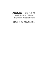
Component Locations
7645
1
27
25
23
22
21
24
18
19
26
28
1112131415
17
8 9
16
2
3
20
10
NOTE: The ISA model is shown above. ISA slots are optional at the time of
purchase. The model without ISA will have 6 PCI slots.
2.3 CUW Component Locations

14 ASUS CUW User’s Manual
3. HARDWARE SETUP
Motherboard Layout
3. H/W SETUP
NOTES: Grayed items are optional at the time of purchase.
The PCI/ISA configuration is dependent on territory.
3.1 Motherboard Layout
COM1
PARALLEL PORT
VGA
PS/2
T: Mouse
B: Keyboard
CPU_FAN
Intel 810
Graphics &
Memory
Controller Hub
(GMCH)
01
DIMM1 (64/72 bit, 168-pin module)
0 1
PWR_FAN
WOR
WOL_CON
CHA
VIDEO
TAD
Socket 370
GAME_AUDIO
Mic
In
Line
Out
Line
In
CHA_FAN
CD
AUX
SMB
PCI1
PCI2
PCI4
PCI3
PANEL
IDELED
FLOPPY
SECONDARY
PRIMARY
ISA
ATX Power Connector
IR
R180
(Clear COMS)
Intel I/O
Controller
Hub (ICH)
01
DIMM2 (64/72 bit, 168-pin module)
2 3
01
DIMM3 (64/72 bit, 168-pin module)
3 2
CR2032 3V
Lithium Cell
CMOS Power
Row
DIP
Switches
PCI5
INTMIC
COM2
LAN_EN
LAN_PWR
SPKEAR
Audio Modem Riser
(AMR)
Bottom:
USB1
USB
2
Multi-I/O
®
CUW
4Mbit
Firmware
Hub
ASUS
ASIC
with Hardware
Monitor
STB_PWR
Audio
Codec
Intel Fast
Ethernet
Audio Codec Setting
2 MB
SDRAM
2 MB
SDRAM
DFP
PCI to ISA
Bridge
LCD
Encoder
PCI6
JEN
VIO
Top:
RJ45
SAFE_MD
NO_REBOOT

ASUS CUW User’s Manual 15
3. HARDWARE SETUP
3.2 Layout Contents
Motherboard Settings
1) JEN p.18 JumperFree™ Mode (Enable/Disable)
2) VIO p.19 I/O Voltage Setting (Normal/+3.66V)
3) AUDIO CODEC p.19 Onboard Audio Setting (Enable/Disable)
4) LAN_EN p.20 Onboard LAN Setting (Enable/Disable)
5) LAN_PWR p.20 Onboard LAN Power Setting (Normal/Standby)
6) SAFE_MD p.21 Safe Mode (Normal/Safe Mode)
7) NO_REBOOT p.21 Automatic Timeout Reboot (Normal/No Reboot)
8) DSW p.22 CPU External Clock (BUS) Frequency Setting
Expansion Slots
1) DIMM1, DIMM2, DIMM3 p.24 168-Pin DIMM Memory Support
2) Socket 370 p.26 Central Processing Unit (CPU) Socket
3) ISA1, ISA2 p.27 16-bit ISA Bus Expansion Slots (optional)
4) PCI1, PCI2, PCI3, PCI4, PCI5 p.27 32-bit PCI Bus Expansion Slots (optional PCI6)
5) AMR p.30 Audio Modem Riser Slot
Connectors
1) PS2KBMS p.31 PS/2 Mouse Connector (6-pin female)
2) PS2KBMS p.31 PS/2 Keyboard Connector (6-pin female)
3) USB p.32 Universal Serial Bus Ports 1 & 2 (Two 4-pin female)
4) PRINTER p.32 Parallel Port Connector (25-pin female)
5) COM1 p.32 Serial Port COM1 Connector (9-pin male)
6) VGA p.33 Monitor (VGA) Output Connector (15-pin female)
7) GAME_AUDIO p.33 Joystick/MIDI Connector (15-pin female) (optional)
8) GAME_AUDIO p.33 Audio Port Connectors (Three 1/8” female) (optional)
9) RJ45 p.33 Fast-Ethernet Port Connector (RJ45) (optional)
10) PRIMARY/SECONDARY p.34 Primary/Secondary IDE Connectors (Two 40-1pins)
11) FLOPPY p.34 Floppy Disk Drive Connector (34-1pins)
12) WOL_CON p.35 Wake-On-LAN Connector (3 pins)
13) WOR p.35 Wake-On-Ring Connector (2 pins)
14) IDELED p.36 IDE Activity LED (2 pins)
15) CHA_, CPU_, PWR_FAN p.36 Chassis, CPU, Power Supply Fan Connectors (Three 3-pin)
16) VIDEO, AUX, CD, TAD p.37 Internal Audio Connectors (Four 4-pins) (optional)
17) SPKEAR p.37 Internal Speaker Connector (4-pins) (optional)
18) IR (CIR/SIR) p.38 Infrared Module Connector (10-1 pins)
19) COM2 p.38 Serial Port COM2 Header (10-1 pins)
Layout Contents
3. H/W SETUP

16 ASUS CUW User’s Manual
20) SMB p.39 SMBus Connector (5-1 pins)
21) DFP p.39 Digital LCD Header (20-1 pins) (optional)
22) INT MIC p.40 Internal Microphone Connector (3 pins)
23) CHA p.41 Chassis Intrusion Connector (2 pins)
24) ATXPWR p.41 ATX Power Supply Connector (20 pins)
25) SPEAKER (PANEL) p.43 System Warning Speaker Connector (4 pins)
26) KEYLOCK (PANEL) p.43 Keyboard Lock Switch Lead (2 pins)
27) PLED (PANEL) p.43 System Power LED Lead (3-1 pins)
28) RESET (PANEL) p.43 Reset Switch Lead (2 pins)
29) PWRSW (PANEL) p.43 ATX Power / Soft-Off Switch Lead (2 pins)
30) SMI (PANEL) p.43 System Management Interrupt Switch Lead (2 pins)
31) LED (PANEL) p.43 System Message LED (2 pins)
3. HARDWARE SETUP
Layout Contents
3. H/W SETUP

ASUS CUW User’s Manual 17
3. HARDWARE SETUP
Motherboard Settings
3. H/W SETUP
3.3 Hardware Setup Procedure
Before using your computer, you must complete the following steps:
• Check Motherboard Settings
• Install Memory Modules
• Install the Central Processing Unit (CPU)
• Install Expansion Cards
• Connect Ribbon Cables, Panel Wires, and Power Supply
3.4 Motherboard Settings
This section explains in detail how to change your motherboard’s function settings
through the use of switches and/or jumpers.
WARNING! Computer motherboards and expansion cards contain very delicate
Integrated Circuit (IC) chips. To protect them against damage from static electric-
ity, you should follow some precautions whenever you work on your computer.
1. Unplug your computer when working on the inside.
2. Use a grounded wrist strap before handling computer components. If you do
not have one, touch both of your hands to a safely grounded object or to a metal
object, such as the power supply case.
3. Hold components by the edges and try not to touch the IC chips, leads or con-
nectors, or other components.
4. Place components on a grounded antistatic pad or on the bag that came with the
component whenever the components are separated from the system.
Motherboard Feature Settings (DSW)
Besides jumper settings, some of the motherboard’s onboard functions are adjusted
through the DIP switches. The white block represents the switch’s position. The
example below shows all the switches in the OFF position.
0 10 10 1
®
CUW
1. Frequency Selection
2. Frequency Selection
3. Frequency Selection
4. Frequency Selection
5. Frequency Selection
CUW DIP Switches
DSW
OFF
ON
ON
12345

18 ASUS CUW User’s Manual
3. HARDWARE SETUP
Motherboard Settings
3. H/W SETUP
1) JumperFree™ Mode Setting (JEN)
This jumper allows you to enable or disable the JumperFree™ mode. The
JumperFree™ mode allows processor settings to be made through the BIOS
setup (see 4.4 Advanced Menu).
NOTE: For JumperFree™ mode, all dip switches (DSW) must be set to OFF.
Setting JEN
Disable (Jumper) [1-2]
Enable (JumperFree) [2-3] (default)
CUW JumperFree™ Mode Setting
Jumper JumperFree
(Default)
123
1
2
3
JEN
0 10 10 1
®
CUW

ASUS CUW User’s Manual 19
3. HARDWARE SETUP
Motherboard Settings
3. H/W SETUP
2) I/O Voltage Setting (VIO)
This jumper allows you to select the voltage supplied to the DRAM, chipset,
PCI, and the CPU’s I/O buffer. The default voltage should be used unless your
processor setting requires a higher voltage.
Setting VIO
Normal [1-2] (default)
3.66V [2-3]
0 10 10 1
®
CUW
CUW Input/Output Voltage Setting
Normal
(Default)
Add 0.1 Volt
123
1
2
3
VIO
WARNING! Using a higher voltage may help when overclocking but may result
in the shortening of your computer component’s life. It is strongly recommended
that you leave this setting on its default.
3) Onboard Audio Setting (AUDIO CODEC) on audio model only
The onboard audio CODEC may be enabled or disabled using all of these jump-
ers. Disable the onboard audio CODEC if you are using an ISA or PCI audio card
on any of the expansion slots or a primary AMR on the AMR slot (see AMR Slot
later in this section). If using an ISA or PCI audio expansion card, Onboard AC’97
Audio Controller in 4.4.2 I/O Device Configuration must also be disabled.
Setting AUDIO CODEC
Enable [1-2] [1-2] [1-2] [1-2] (default)
Disable [2-3] [2-3] [2-3] [2-3]
0 10 10 1
®
CUW
CUW Audio Codec Setting
DisableEnable
(Default)
1
2
3
1
2
3
SPK
ADN#
AUD_EN1
AUD_EN2
SPK
ADN#
AUD_EN1
AUD_EN2

20 ASUS CUW User’s Manual
3. HARDWARE SETUP
Motherboard Settings
3. H/W SETUP
4) Onboard LAN Setting (LAN_EN) on LAN model only
The onboard LAN may be enabled or disabled by this jumper.
Setting LAN_EN
Enable [1-2] (default)
Disable [2-3]
0 10 10 1
®
CUW
CUW LAN Setting
Enable
(Default)
Disable
123
1
2
3
LAN_EN
5) Onboard LAN Power Setting (LAN_PWR) on LAN model only
The onboard LAN power may be set to normal or standby power. Select Nor-
mal if you do not have a power supply with 720mA standby power. Selecting
Standby will allow the use of Wake-On-LAN but may not allow system bootup
if the power supply’s standby power is insufficient.
Setting LAN_PWR
Normal [1-2]
Standby [2-3] (default)
0 10 10 1
®
CUW
CUW LAN Power Setting
Normal Standby
(Default)
123
1
2
3
LAN_PWR
/