Page is loading ...

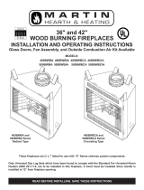
36" and 42"
FACTORY-BUILT WOOD BURNING
FIREPLACES FOR MANUFACTURED HOMES
INSTALLATION AND OPERATING INSTRUCTIONS
READ BEFORE INSTALLING. SAVE THESE INSTRUCTIONS
MODELS
BWBC400MHB
BWBC500MHB
FACTORY-BUILT FIREPLACES
U.L. FILE NO. MH7603
These fireplaces have been tested
to U.L. Safety Standard 127, and
listed by
Underwriters Laboratories, Inc.
Look for the UL listing mark on
your fireplace.
CONGRATULATIONS!
You have chosen the finest wood burning fireplace available. Your fireplace has been
designed for years of heating and viewing enjoyment. Please take time to read this entire
manual before installing or operating your fireplace.

2 61D0087
CONTENTS
Listing and Code Approval .............................................. 2
Important Safety Information .......................................... 3
Fireplace Usage ................................................................ 4
Product Features .............................................................. 5
How This Fireplace Works ............................................... 6
Fireplace Location ............................................................ 8
Fireplace Dimensions ...................................................... 9
Fireplace Installation ........................................................ 9
Safety Strip Installation .............................................. 10
Hearth Extension ....................................................... 10
Unpacking Fireplace .................................................. 12
Clearances ................................................................. 12
Chimney Installation ...................................................... 14
Installing Chimney Safety Information ....................... 14
Firestop and Chimney Installation .............................. 15
Elbow Installation ....................................................... 17
Offset Installation Sequence ...................................... 18
Chimney Cap Installation ........................................... 19
Outside Combustion Air ............................................... 21
Precautions and Recommendations ......................... 21
Model AK6A Combustion Air Assembly ...................... 21
Trim and Mantel Installation for Wood Burning
Fireplaces ................................................................ 22
Locating Front and Side Clearances .......................... 22
Locating Mantel .......................................................... 23
Fan Assembly ................................................................. 23
Glass Door Installation .................................................. 24
Removing Glass Doors .............................................. 24
Replacing a Glass Panel ............................................ 25
Reinstalling Glass Door ............................................. 26
Fireplace Operation ........................................................ 27
Advantages of a Wood Burning Fireplace ................. 27
Which Woods Are Best .............................................. 27
Disposal of Ashes ...................................................... 27
Building and Tending a Fire ....................................... 28
Wood vs. Fossil Fuels ................................................ 28
Glass Doors ............................................................... 29
Maintenance .................................................................... 30
Fireplace Maintenance ............................................... 30
Glass Door Maintenance ........................................... 30
Refractory Components Maintenance ....................... 31
Chimney Maintenance ............................................... 32
Checklist of DOs and DON’Ts .................................... 33
Replacement parts ......................................................... 34
Warranty .......................................................... Back Cover
LISTING AND CODE APPROVALS
The UL listing mark on the fireplace indicates that the fireplace is listed by Underwriters Laboratories, Inc., to U.L. 127 Safety
Standard For Factory-Built Fireplaces. The design of this fireplace and these instructions complied with the applicable U.L.
127 safety standards for a factory-built fireplace in effect at the time the fireplace was manufactured. You should be aware,
however, that failure to properly install, operate, and maintain this or any other factory-built fireplace can result in a home
fire or other occurrences that could cause deaths, injuries, and property damage. It is very important that the persons install-
ing and/or supervising the installation of this fireplace have appropriate skills in using the tools and techniques required; and
reading and comprehension skills sufficient to read and follow these instructions.
These instructions contain warnings, cautions, and notes to emphasize important safety information. To assure that safe and
satisfactory service is received from this fireplace, please read all contents of this manual. The instructions contained in this
manual are in compliance with the requirements of the Department of Housing and Urban Development HUD) “Manufactured
Home Construction and Safety Standards”, and the National Fire Protection Association Safety Standard 211. Before begin-
ning the fireplace installation, you should check with local building officials to obtain required permits and assure compliance
with local regulations and codes. If you encounter problems with code requirements, contact you dealer for assistance.

61D0087 3
INSTALLER
Please leave these instructions with the owner.
OWNER
Please retain these instructions for future reference
.
IMPORTANT SAFETY INFORMATION
Do not use a fireplace insert or other
product not specified for use with
this fireplace.
CAUTION
Improper installation or use of this fireplace will void its warranty and can cause:
• Damage to the fireplace from overheating.
• Hazardous temperatures to develop on combustible materials adjacent to the fireplace
or chimney.
• The emission of smoke, sparks or hazardous gases into the dwelling.
• Leakage of rain water into the dwelling.
WARNING
• Read these instructions entirely before beginning any part of the installation. Save
these instructions for any future repairs.
• Use these instructions as a guide during the installation of the fireplace.
• Install all the parts used with this fireplace system in accordance with these installation
instructions. Failure to do so may be hazardous and will void the warranty.
• Do not alter fireplace and accessories in any way that is not specifically recommended
in this manual.
• Do not install fireplace with a masonry flue.
• Do not pack required air spaces with combustible material or insulation not specifically
recommended for use in such areas.
• When installed in a manufactured home, this fireplace must be equipped with glass
doors and accessories for supplying outside air for combustion.
• WARNING: DO NOT INSTALL IN SLEEPING ROOM OF A MANUFACTURED HOME.
• This fireplace and chimney should not be used for venting a wood or coal burning
heater or fireplace insert.
WARNING

4 61D0087
FIREPLACE USAGE
These fireplaces are for use in manufactured homes. Burn solid wood fuel only or use only with one of the gas log appli-
ances described below. These fireplaces are intended for supplemental heating only and are not intended for use as a primary
heating system.
These fireplaces are designed to sit directly on a combustible floor. Except as noted by this instruction manual, only parts
manufactured by Monessen Hearth Systems. and labeled for use with these specific fireplaces should be used in the instal-
lation and operation of these fireplaces. The use of improper parts in the installation and operation of these fireplaces can be
hazardous and voids the warranty.
Do not use this fireplace and chimney for venting a solid fuel heater or fireplace insert
unless written authorization is given by Monessen Hearth Systems. Failure to heed
this warning may cause a fire hazard and will void the Monessen Hearth System
Warranty.
WARNING
These fireplaces have provision for a gas line connection. The provision for a gas line
is intended only for connecting one of the gas appliances (gas log sets) described by
the following paragraph.
NOTICE
Install only gas log sets which have been tested and certified for installation in these fireplaces in an
aftermarket (completion of sale, not for purpose of resale from the manufacturer) manufactured home,
where not prohibited by state or local codes.
These gas log sets…
have an automatic shutoff device;
comply with applicable standards for gas appliances;
have been tested and certified by a nationally recognized organization for installation in these specific
fireplaces.
These fireplaces have been found to comply with the standard for factory-built fireplaces,
UL 127, when installed with unvented gas logs sets. However, state or local codes may
only allow operation of gas log appliances in a vented configuration. Check your state
or local codes.
NOTICE
When using a decorative gas log appliance in these fireplaces, the fireplace damper
must set in the fully open position. Note: A gas log appliance classified as decorative
is not thermostatically controlled, must be vented and its primary function lies in the
esthetic effect of the flame.
CAUTION

61D0087 5
FIREPLACE USAGE
If a gas appliance is installed in one of the fireplaces, installation must be in accordance
with nation fuel gas code ANSI Z223.1 Guidelines for safely installing and operating one
of the gas appliances (gas lot set) described above are contained in the instructions
provided with the gas appliance.The installer of the gas appliance must describe the
operation of the fireplace and gas appliance to the individuals who will be operating
them. Instruction manuals must be left with operator of the system.
CAUTION
While a gas log appliance is
installed in one of these fireplaces,
solid fuels must not be burned in
the fireplace.
CAUTION
PRODUCT FEATURES
• This fireplace is designed to burn solid
wood fuel (wood), UL-classified processed
solid fuel fire logs, or a certified decorative
gas appliance may be installed in the fire-
place as described later by this instruction
manual.
• The appliance must be properly connected
to a venting system.
PRODUCT SPECIFICATIONS
Figure 1 - BWBC400/500MHB
Screens
Grate
Fan
Switch
Glass
Doors
Nail Down
Strap

6 61D0087
As wood is burned in the fireplace, room air enters
the fireplace through its “cool air inlet”, circulates
around the firebox, and exits the fireplace through its
“warm air outlet.” See Figure 2. This air circulation
cools the firebox.
HOW THIS FIREPLACE WORKS
Do not block or restrict air
circulation in any manner.
Blocking or restricting
the air flow will cause the
firebox to reach hazardous
temperatures.
WARNING
Figure 2 - Location of Cool Air Inlet and Warm Air Outlet
Warm Air
Outlet
Cool Air
Inlet
The fireplace will go
through a curing process
(burning off oil residue,
etc.) the first few times it
is fired. Smoke and fumes
may be emitted from its
upper grille. Open a door
or window to let any
smoke or fumes escape
during curing period.
WARNING

61D0087 7
For large fires, the maximum heating benefit from the fireplace will be
obtained with its glass doors fully open. The open doors will allow more
radiant heat to be emitted out of the front opening of the fireplace. When
the glass doors are open, close the fireplace’s mesh screens
to help keep burning embers from popping out of the firebox.
With a small fire, it is best to operate the fireplace with its glass doors
fully closed to prevent excessive room air from being drawn up the
chimney. To prevent room air from escaping up the chimney overnight,
close the fireplace glass doors before retiring in the evenings.
With the provided AK6A combustion air kit installed on the
fireplace, outside combustion air may enter the firebox through
a dampered opening located on the left side of the fireplace.
This feature reduces the room air used for combustion and
prevents excessive heat loss from the room. When the fire-
place is in use, this damper should be open. When the
fireplace is not in use, the damper may be closed to prevent
cold air from entering the firebox. The outside combustion
air control lever is located inside the fireplace firebox just
above the brick panel on the left side of the firebox as shown
by Figure 5.
NOTE: Outside combustion air damper is open when
its control lever is up. The damper is closed
when its control lever is down.
The fireplace must be supplied with outside combustion air
when the fireplace is installed in a manufactured home. See the
Outside Combustible Air section of this manual for additional
information about outside combustion air.
This fireplace is equipped with a factory-installed fan assem-
bly to help circulate heat produced by the fireplace. The fanʼs
ON/OFF rocker switch is installed in the left side of the lower
louver panel on the front of the fireplace. Use the ON/OFF
rocker switch to turn the fan on and off as desired for heat
circulation. See the Wiring for Fan Assembly, page 27 of this
manual for additional information about fan assembly.
Figure 3 - Correct Position
Figure 4 - Incorrect Position
The fireplace should be operated only with
its glass doors fully open or fully closed. If
glass doors are left partially open, gas and
flame may be drawn out of fireplace opening.
This creates risks of both fire and smoke. See
Figures 3 and 4.
WARNING
Fireplace
Fireplace
Glass Doors Fully Open
Glass Doors Partially
Open
Do not
operate
fireplace like
this!
HOW THIS FIREPLACE WORKS
Figure 5 - Outside Combustion Air Control Lever Location
Air Combustion Control Lever

8 61D0087
Do not install fireplace
over carpeting.
CAUTION
FIREPLACE LOCATION
The following factors should be taken into consideration:
• This fireplace should have sufficient access for its safe operation and main-
tenance.
• The SVTR firestop thimble allows chimney to be passed between joist and
rafters or trusses placed 16" on center. See Chimney Installation, page 14.
• Locate a position where the flue system of the fireplace can be properly installed without damaging the integrity of the
building. e.g. cutting wall or ceiling joist (example: load-bearing framing members).
• Install floor protection when the appliance is installed directly on tile or other combustible material.
• No special foundation is needed for this fireplace. If fireplace is trimmed with large stone or brick facing, make sure the
foundation will support those materials.
• Check fireplace and flue system clearance requirements.
• Locate the fireplace in a large and open room that is centrally located in the house. This will optimize heat circulation
and comfort.
• Locate fireplace away from frequently opened doors, central heat outlets or returns, or other places where air movements
may disturb the airflow around the fireplace.
Note: Air turbulence near the fireplace may cause smoke to spill out of the fireplace opening.
• Locate fireplace near a load bearing wall. Make sure the support structure is strong enough or reinforced if fireplace is
to be trimmed with a heavy stone or brick facing and hearth extension.
• This fireplace may be installed along a wall, across a corner, or use an exterior chase. See Figure 6 for suggested loca-
tions.
• Location should be out of high traffic areas and away from furniture and draperies.
• Never obstruct the front opening of the fireplace.
• Do not install in the vicinity where gasoline or other flammable liquids are stored.
• See Chimney Installation, pages 14 through 20 for allowable venting configurations.
• Minimum clearances to combustibles, side-wall, ceiling, woodwork, and windows must be maintained. See Clearances,
page 13 and 14.
Figure 6 - Suggested Fireplace Locations

61D0087 9
A
71/2"
61/2"
61/2"
343/8"
1/2" or 5/8"
Drywall Spacers
21"
10"131/2"
211/2"
25/8"
171/4"
7"
97/8"
Gas
95/8"
Air Kit
1/2" or 5/8"
Drywall
Spacers
133/4"
Electrical
213/4"
Framing
Dimension
403/4"
Framing
Dimension
C
Framing Dimension
B
TOP VIEW
FRONT VIEW SIDE VIEW
BWBC400MHB
BWBC500MHB
Outside
Connector
Center
Line
FIREPLACE DIMENSIONS
Figure 7 - Fireplace Dimensions
400 500
Units Units
A 243/4" 303/4"
B 36" 42"
C 401/2" 461/2"
1. Place fireplace in the desired location. Securely support and level fireplace. Check face of the fireplace with a carpenterʼs
level. If fireplace is not plumb, correct it by placing shims under the edges of fireplace.
2. Block in the fireplace to prevent any shifting of firebox. Secure fireplace with naildown straps located on each side of
the fireplace. See Figure 1, Page 5.Do not enclose the fireplace until the combustion air duct and chimney pipes are
installed.
3. Connect fireplace fan assembly to homeʼs electrical system.
4. Trim and enclose fireplace.
5. Install hearth extension or equivalent. See pages 10 and 11.
Note: Some local codes may require electrically grounding the fireplace and chimney.
FIREPLACE INSTALLATION

10 61D0087
52" (400 Models)
66" (500 Models)
16" Min.
(400 Unit)
20" Min.
(500 Unit)
21"
211/2"
401/2"
401/8" (400 Unit)
461/8" (500 Unit)
SAFETY STRIP INSTALLATION
You must place the metal safety strip (packed with your fireplace in two pieces) beneath the fireplace front before installing
hearth extension Slide safety strip approximately 11/2" under the fireplace. The hearth extension will install on top of the
safety strip. See Figures 8 and 9.
HEARTH EXTENSION
For manufactured home installations, use the Model H1652 (400 unit) or Model H2066 (500 unit) hearth extension or an
equivalent hearth extension* acceptable to the authority having jurisdiction. The hearth extension must cover an area 16"
(400 unit) or 20" (500 unit) in front of, and 8" either side of the fireplace opening. See Figures 8 and 9. If a raised hearth
extension is desired, the fireplace must be elevated accordingly and positioned on a platform constructed of combustible or
noncombustible materials.
The hearth extension may be covered with tile or any noncombustible material. The hearth extension assembly must not
block lower louvered panel.
Note: Do not install hearth extension until after fireplace and chimney have been installed.
FIREPLACE INSTALLATION
Figure 8 - Installing Hearth Extension
Gas
Opening
Junction
Box
Opening
Floor
Level
Safety
Strip
Hearth
Extension
Hearth Extension Clearances & Width
400 Unit 500 Unit
On Both Sides 8" Min. 8" Min.
Front of Fireplace 16" Min. 20" Min.
Extension Width 52" 66"

61D0087 11
16"min. - 400 unit
20" min. - 500 unit
8"8"
Figure 9 - Installing Hearth Extension and Metal Safety Strip
Only install metal safety
strip horizontal to the
fireplace.
WARNING
Fireplace
Metal
Safety Strip
*HEARTH EXTENSION EQUIVALENTS
Hearth extensions are made of a 1/2" thick piece of **MICORE CV230 fiberboard covered with a sheet of 26 gauge galvanized
steel. You may purchase these materials locally to fabricate hearth extensions. You can construct hearth extensions from any
noncombustible material that is 1/2" thick with a “K” value (thermoconductivity) of 0.43 or lower.
For example, an insulating material 1/2" thick with a “K” value of 0.35 would be acceptable. A hearth extension made from
materials 1/2" thick with a “K” value of 0.43 or lower is equal to the H1652 or H2066 hearth extensions. See Figure 8, page
10.
**MICORE CV230 is manufactured by U.S. Gypsum Corporation.
The following relations could be useful:
C = K divided by the material thickness
(Example C = .43 divided by 1/2 (.50)
C = .86)
K = C multiplies by the material thickness
(Example K = .86 multiplied by 1/2 (.50)
K = .43)
R = The material thickness divided by K
(Example R = 1/2 (.50) divided by .43
R = 1.16)
C = Thermal Conductant
R = Thermal Resistance
FIREPLACE INSTALLATION

12 61D0087
FIREPLACE INSTALLATION
UNPACKING FIREPLACE
Unpack and check the fireplace and chimney for damage. If any items are been damaged or missing, contact your Monessen
Hearth Systems dealer. Do not substitute parts. Use only parts listed for use with Monessen Hearth Systems Models
BWBC400MHB and BWBC500MHB fireplaces.
CLEARANCES
Provide required clearances shown in Figures 10 through 12. Provide 2" minimum chimney air space clearance to combus-
tibles.
Figure 10 - Minimum Clearances for Corner Installation
Figure 11 - Minimum Clearances for Side Wall Installation
AK6 Combustion Air
Kit Installed through
Outside Wall
(AK6 Kit Optional to
AK6A Kit Supplied with
Fireplace)
AK6A Combustion Air
Kit Installed through
Floor
(AK6A Kit Supplied with
Fireplace)

61D0087 13
10' min. Height
Storm
Collar
Bottom of Fireplace
Warm Air Outlet —
Do Not Block!
Galvanized Metal Strip
Glass Door Accessory
Cool Air Inlet — Do not Block!
Round Chimney Cap
Model SC
Flue
Outlet
Height
Roof Flashing Model 612
Top Spacer
Flexible Duct
Type FP-6-U
Nail Down Strap
Combustion
Air Assembly
Model AK6A
Front-to-Back
Framing Dimensions
403/4"
Framing
Dimension
401/2" - 400 Units
461/2" - 500 Units
Framing
Dimension
213/4"
Chimney (2" min. Air Space)
to Combustibles —
S12 1' Pipe
S18 18" Pipe
S36 3' Pipe
S48 4' Pipe
Hearth Extension
Firestop Thimble - Model SVTR
(Requires 141/2"x141/2" Opening)
Zero Clearance to Combustibles
FIREPLACE INSTALLATION
CLEARANCES (CONTINUED)
Figure 12 - Proper Clearances and Chimney Height
• You must use Model SVTR Thimble
• It is recommended for safety and
reducing heat loss that firestopping
be used at the ceiling level for chase
installation even if local codes do not
require firestopping.
• Do not insulate chase with blown or fill
type insulation. Only allow insulation
to come into contact with fireplace at
points where fireplace would normally
be contacted by framing materials.
• Combustible materials must not be
installed below top spacers.
• Non-combustible materials must not
cover warm air outlet and/or cool air
inlet.
WARNING

14 61D0087
For your safety, some of the important things to remember in regard to chimneys are
listed below:
• Use only parts and accessories labeled for use with this fireplace.
• Use only undamaged parts and accessories.
• Enclose the chimney where it passes through the living spaces to prevent contact with
and possible damage to the chimney.
• There must be least 2" of air space separating all chimney sections from combustible
materials THROUGHOUT THE CHIMNEY SYSTEM.
• Install firestop spacers at ceiling level.
• Install the proper chimney cap or chimney housing on the chimney to prevent the entry
of rain and debris into the chimney and to assure the proper venting of smoke.
WARNING
Note: To select the proper chimney height, see Figures 12 through 15. The flue outlet must be a minimum
of 3' above the highest point where the chimney penetrates the roof and a minimum of 2' above all portions
of the building within ten feet. If the chimney is to include elbows to offset the chimney, see Chimney Offset
and Cap Installation Section. There must be at least 2" air space between all sections of the chimney and
combustible materials between floors.
Do not extend the chimney more than 90" above the roof without additional support.
CHIMNEY INSTALLATION
INSTALLING CHIMNEY SAFETY INFORMATION
You must properly install the chimney to assure safe and satisfactory performance of the fireplace. This is an important part
of the installation. Review the Chimney Installation Section thoroughly.
SMH Chimney Kit and SMH2 Chimney Kits are used most often in contemporary fireplace installations. If you plan to use
the SMH or SMH2 Chimney Kit, check to make sure you have all parts. If you are missing any parts, contact dealer where
you bought fireplace.
Quantity for SMH Chimney Kit Quantity for SMH2 Chimney Kit
612 flashing 1 1
SC chimney cap with storm collar 1 1
S36 chimney sections 3 2
SVTR thimble 1 1
S18 chimney sections 0 2

61D0087 15
CHIMNEY INSTALLATION
Figure 13 - Standard Roof
FIRESTOP THIMBLE AND THIMBLE EXTENSION
A firestop thimble is required in the chimney installation of all fireplaces safety-certified for installation in manufactured
homes. For shielding purposes, the firestop thimble must pass through the manufactured home ceiling and extend up to the
roof line of the manufactured home. See Figures 13 through 15. When an extension is needed, a thimble extension must
be installed along with the firestop thimble. Models SVTR and SVTE thimble extensions have been safety-certified for use
with this fireplace and should be installed as follows.
1. Lay out, cut and frame a square opening through the ceiling and roof structure at the point where the chimney will pass
through. The SVTR firestop thimble requires a 14½"x14½" square opening. If the chimney is to go through a pitched
roof, the hole in the roof must be rectangular instead of square. A 7½° pitch requires 14½"x14¾" framing. A 15° pitch
requires a 14½"x15" framed opening.
2. Install the SVTR firestop thimble as shown in Figure 13. Nail it securely to the framing members. The firestop thimble
should extend completely through the roof structure to shield combustible construction materials. If the SVTE thimble
extension is needed, it should overlap the firestop thimble a minimum of 1". Screws should be used to secure the thimble
extension to the firestop thimble. See Figure 14.
Figure 14 - Pitched Roof with
Attic Space
Trim off SVTR Firestop
Thimble as Needed to
Seat Flashing
Storm Collar
Flashing
Use Nails to Secure
Firestop Thimble as
Shown
SVTR
Firestop
Thimble
Requires a
14½" x 14½"
Framed
Opening
612 Roof
Flashing
SVTE Thimble
Extension*
Secure SVTE
Thimble
Extension with
Screws as
Shown
* The SVTE Thimble Extension is required …
1. In unvented attic space if attic space exceeds 8"
2. In vented attic space if total chimney height from floor to flue outlet is less than 13½'
Continued
SVTR
Firestop
Thimble

16 61D0087
FIRESTOP THIMBLE AND THIMBLE EXTENSION (CONTINUED)
3. For unventilated cathedral type ceiling on double-wide manufactured homes, the firestop thimble should extend through
both the ceiling and roof structures. See Figure 15.
4. Install first chimney section by inserting the male end of the flue (the smallest diameter pipe) into the flue collar of the
fireplace. Press down until the snap locks engage. Place the female end of the 11" diameter pipe on top of the fireplace
and press down until the snap locks engage. Continue this process, until the chimney is at least 8" to 16" above the
roof opening for installation of the Model SC Chimney Cap later. At this point, the chimney must not exceed 13½' road
clearance. This will allow the top section of chimney and chimney cap or chimney housing to be removed for moving
the manufactured home on the highway.
Note: If additional strength of the outer pipe joints is desired, place (2) or three (3) sheet metal screws
through the area where the outer pipes overlap one another. Install these screws by drilling a 1/8"
diameter hole through the chimney sections.
Be very careful when drilling holes into
outer pipe. The drill must not penetrate
the inner stainless steel pipe.
WARNING
5. Make sure all joints of the chimney are tight. Check clearance between the chimney and combustible materials before
proceeding with installation of the roof flashing and chimney cap.
Figure 15 - Unvented Cathedral Type Ceiling
SVTR Firestop Thimble May Be
Trimmed Off Flush with Roof Line if
It interferes with Flashing
SVTR Firestop Thimble
(Swivels 0 to 15°)
• 7 ½° Pitch Requires 14½" x 14¾" Framed
Opening
• 15° Pitch Required 14½" x 15" Framed
Opening.
CHIMNEY INSTALLATION

61D0087 17
ELBOW INSTALLATION
The following are important points that should be observed when
installing elbows on the fireplace.
1. Securely nail down all four (4) support straps to the surround-
ing structure of all elbows not installed directly on top of the
fireplace.
IMPORTANT: Use a minimum of two (2) 8-penny nails per
strap. This allows the support strap to carry the weight of the
chimney above the elbow and prevents this weight from break-
ing the elbow or chimney sections apart.
2. Do not use elbows in any combination that inclines the chimney
more than 30° from vertical. See Figure 16.
3. The minimum height of the fireplace and chimney system when
using 1 pair of elbows is 13'
Air Inlet Pipe
Flue Pipe
30° Elbow
Figure 16 - Elbow Supports
CHIMNEY INSTALLATION
Figure 17 - Typical Chimney Offset Installation
Storm Collar
612 Flashing
Roof
Support Straps
4. Inclined portions of chimney are often used as stor-
age. Enclose the inclined portions of chimney that
pass through living spaces to avoid contact with and
possible damage to chimney. Maintain minimum air
space of 2" between chimney and enclosing. See
Figure 17.
5. The length of inclined portion of chimney between
elbows must not exceed 6' if it is not supported.
The length of inclined portion of chimney between
elbows must not exceed 20' if it is supported every
6' with metal support straps.
6. When enclosing the elbows and inclined portions of
the chimney, enclosing materials must be installed
vertically to maintain the required 2"minimum air
space clearance to the chimney at the extremities
of the offset. It is best that enclosing material not
follow inclined portions of chimney.
Maintain 2"
Minimum Air Space
Clearance to
Combustibles
SC Chimney
Cap
“S” Series
Chimney
Components
SVTR
Firestop
Thimble
(0°-15° Pitch)
SE30
Elbows

18 61D0087
CHIIMNEY INSTALLATION
OFFSET INSTALLATION SEQUENCE
Determine the location and amount of offset required. Select the combinations of chimney sections and elbows required
from the Chimney Height and Offset Charts.
Continued
Height
(Inches)
Intermediate Sections
12" 18" 36" 48"
35
39
47
0
2
0
0
1
0
1
0
0
0
0
1
52
58
64
0
1
0
1
0
1
0
0
1
0
1
1
70
75
82
0
1
0
0
1
0
2
0
1
0
1
1
87
94
99
0
0
0
1
0
1
2
0
1
0
2
1
105
111
117
0
0
0
0
1
0
3
0
2
0
2
1
122
129
134
0
0
0
1
0
1
3
1
2
0
2
1
141
146
152
0
0
0
0
1
0
0
1
3
3
2
1
158
164
169
0
0
0
1
0
1
0
2
3
3
2
1
176
181
188
0
0
0
0
1
0
1
2
0
3
2
4
193
199
205
0
0
0
1
0
1
1
3
0
3
2
4
211
216
223
0
0
0
0
1
0
2
3
1
3
2
4
228
235
240
0
0
0
1
0
1
2
0
1
3
5
4
246
252
258
0
0
0
0
1
0
3
0
2
3
5
4
263
270
275
0
0
0
1
0
1
3
1
2
3
5
4
282
287
293
0
0
0
0
1
0
0
1
3
6
5
4
293
305
310
1
0
0
0
0
1
0
2
3
6
5
4
317
322
329
0
0
0
0
1
0
1
2
0
6
5
7
Height
(Inches)
Intermediate Sections
12" 18" 36" 48"
334
340
346
0
0
0
1
0
1
1
3
0
6
5
7
CHIMNEY HEIGHT CHART (FROM TOP OF UNIT OR FINISHED HEARTH)
Elbow
Set
Chimney Sections Total
Inches
OffSet
Total
Inches
Rise
12" 18" 36" 48"
1
1
1
0
1
0
0
0
1
0
0
0
0
0
0
41/2
10
13
17
261/2
313/4
1
1
1
2
1
0
0
1
0
0
0
1
0
0
0
151/2
151/2
22
36
411/4
471/4
1
1
1
2
0
20
1
0
1
0
0
1
0
1
0
24
28
301/2
503/4
573/4
62
1
1
1
1
0
0
0
1
0
0
0
2
1
1
0
331/2
361/2
391/2
673/4
721/2
771/2
1
1
1
1
0
0
1
0
1
0
1
2
1
1
0
42
451/2
48
82
88
921/4
1
1
1
0
0
0
0
1
0
0
1
3
2
1
0
511/2
54
57
981/2
1023/4
1073/4
1
1
1
0
0
0
1
0
1
0
2
3
2
1
0
60
63
651/2
1131/4
1181/4
1221/2
1
1
1
0
0
0
0
1
0
1
2
0
2
1
3
69
711/2
75
1283/4
133
1391/4
1
1
1
0
0
0
1
0
1
1
3
0
2
1
3
771/2
801/2
831/2
1431/2
1431/2
154
1
1
1
0
0
0
0
1
0
2
3
1
2
1
3
861/2
89
921/2
159
1631/4
1691/2
1
1
1
0
0
0
1
0
1
2
0
1
2
4
3
95
981/2
101
1733/4
180
1841/4
1
1
1
0
0
0
0
1
0
3
0
2
2
4
3
104
107
110
1891/4
1943/4
1993/4
1
1
1
0
0
0
1
0
1
3
1
2
2
4
3
1121/2
116
1181/2
204
2101/4
2141/2
1 0 0 0 5 122 2203/4
Height
(Inches)
Intermediate Sections
12" 18" 36" 48"
352
357
364
0
0
0
0
1
0
2
3
1
6
5
7
369
376
0
0
1
0
2
0
6
8
CHIMNEY SECTIONS
WITH ELBOW OFFSETS
STRAIGHT RUN
CHIMNEYS
Chimney support is required at
25' chimney height.
CHIMNEYS WITH
ELBOW OFFSETS
The length of the inclined por-
tion of the chimney between
elbows must not exceed 6' when
unsupported.
The length of the inclined por-
tion of the chimney between
elbows must not exceed 20' if
the chimney is supported at 6'
intervals using either metal sup-
port straps or an SCS chimney
support.
The SCS chimney support when
installed at a 30° angle will add
8' of rise and 45/8" of offset to the
chimney height calculations.

61D0087 19
3' min.
2' min.
10'
CHIIMNEY INSTALLATION
OFFSET INSTALLATION SEQUENCE (CONTINUED)
1. Install the first SE30 elbow by placing the male end of the 8" diameter flue elbow into the mating part of the fireplace
or chimney section. Press down until the snap locks engage.
2. Insert the female end of the 11" diameter outer elbow onto the mating part of the fireplace or chimney section . Press
down until the snap locks engage.
3. Nail the support straps to the framing member with a minimum of two (2) 8-penny nails per strap.
4. Install the sections of pipe between elbows until the proper number of chimney sections have been installed.
5. Install the second elbow to return the run of the chimney to vertical.
6. Nail the support straps of the second elbow to a building frame member.
7. Continue installing the vertical portion of the chimney.
CHIMNEY CAP INSTALLATION
MODEL SC CHIMNEY CAP
Note: The proper chimney height is important to assure proper draft and safety.The SCchimney cap
must extend the flue outlet 4" above the top of the last section of chimney. Keep this mind when
determining the proper height for the chimney. The chimney should not be extended more than
90" above the supporting roof structure without additional support.
Figure 18 - Proper Chimney Height
SC Chimney
Cap
For safety and proper draft, the chimney must be at least 3' higher than
the highest point where it passes through the roof. It also must be at least
2' higher than the highest part of the roof or structure that is within 10' of
the chimney. See Figure 18.
CAUTION

20 61D0087
CHIIMNEY INSTALLATION
1. Extend the regular chimney sections until the top of the chimney is
4" below the total flue height desired.
2. Remove the shingles from around the chimney so that the flashing
may be installed and sealed.
For metal roofs: Install flashing on top of roof covering. Nail
flashing down with at least eight (8) nails.
For standard roofing shingles: Remove the shingles from
around the chimney so that the flashing may be installed. Install the
upper part of the flashing under the shingles.
3. Set the flashing on the roof. Scribe a line around the flashing. Cut
1/4" below the scribed line. This should increase the diameter of the
flashing outlet enough to allow the flashing to be placed over the
chimney. See Figure 19.
4. Seal crack between the top of the flashing and the chimney with
mastic. Leave some excess mastic at this area to be used by Step 6
below.
Use pliers and wear gloves when
handling the storm collar The edge of
the storm collar is sharp. If you are not
careful, you could cut your hands.
CAUTION
CHIMNEY CAP INSTALLATION (CONTINUED)
Figure 19 - Cutting Off Top of the
Flashing
Top of
Flashing
Figure 20 - Installing Storm Collar
and Chimney Cap
Model SC
Chimney Cap
Apply Mastic
Here
Storm Collar
Flashing
7. Place chimney cap into matching parts of the last chimney section. Push chimney cap down until the brackets on the
bottom of the chimney cap sits on the chimney pipe. Punch or drill 1/8" diameter holes in the inlet air duct (chimney
pipe) where specified on the brackets. Fasten chimney pipe down with the No. 8 screws provided. See Figure 20.
Note: Do not penetrate the inner stainless steel pipe while installing the screws.
8. Check all the parts of the fireplace, chimney and chimney termination cap. Make sure none have been damaged or bent
during installation. Check to see that all parts have been properly installed.
Note: The metal used for chimney cap has a rust-protective coating but the cut edges of the parts are not
protected. Detergent-wash and paint exposed parts of chimney cap with galvanized primer paint.
This will prevent rusting and rust staining of nearby structures.
5. Place the storm collar around the chimney and put collar
together like a belt in belt loops. With the loops facing
up, slide the end of collar under the two loops on the
other end. Overlap the ends of the collar until it is tight
against the chimney. Bend the free end of the collar back
over the loops to hold the storm collar securely together.
Trim off the excess ends of the storm collar.
6. Slide storm collar down snugly against the flashing until
the excess mastic left in step six is forced up into crack
between the storm collar and chimney. This will make the
joint between the flashing and the chimney watertight.
See Figure 20.
Be careful to avoid electrical shock
hazard when contacting wires to
metal chimney components.
CAUTION
Base of Flashing
under Shingles
Standard Roofing
Shingles
/