ICP DIO-144 Quick Start

Type
Quick Start

This manual is also suitable for

- 1 -
Language
English
Version V1.2
Update Nov.2008
………………………………………………
What’s on your package?
One DIO-96/144 card
One companion ISA CD (V2.1 or later)
One Quick Start Guide(this document)
………………………………………………
Installing Windows Driver
Follow those steps:
1. Setup the Windows driver.
You can get the driver from:
CD:\NAPDOS\ISA\DIO\DLL\
http://ftp.icpdas.com/pub/cd/iocard/isa/napdos/isa/dio/dll/
1
2
DIO
-
96/144
- 2 -
2. Click button to start installation.
3. Click button to install driver into the
default folder.
4. Click button to continue installation.
5. Select “NO, I will restart my computer later” and then
click button.
………………………………………………
I/O Base Address/Interrupt Setting
The base address is set from SW1 DIP switch on board:
The Interrupt Level Setting
3
Windows driver
support windows 98/NT/2000
and
XP/2003/vista 32-bit versions.
DIO-96
SW1
ON
1
2
3
4
5
6
A9
A8
A7
A6
A5
A4
SW1 Value Table (*):Default setting
1 2 3
4 5 6
I/O
Address
A9
A8
A7
A6
A5
A4
200 1 0 0
0 0 0
210 1 0 0
0 0 1
.
2C0(*)
1 0 1
1 0 0
.
300 1 1 0
0 0 0
310 1 1 0
0 0 1
.
3F0 1 1 1
1 1 1
SW1
ON
1
2
3
4
5
6
A9
A8
A7
A6
A5
SW1 Value Table (*):Default setting
1 2 3
4 5 6
I/O
Address
A9
A8
A7
A6
A5
X
200 1 0 0
0 0 X
220 1 0 0
0 1 X
.
X
2C0(*)
1 0 1
1 0 X
2E0 1 0 1
1 1 X
.
X
300 1 1 0
0 0 X
.
X
3E0 1 1 1
1 1 X
DIO-144
- 3 -
………………………………………………
Installing Hardware on PC
Follow those steps:
1. Shut down and power off your computer
2. Remove all covers from the computer
3. Select an empty ISA slot
4. Carefully insert your I/O card into the ISA slot
5. Replace the PC covers
6. Power on the computer
After powering-on the computer, continue next process.
………………………………………………
Adding Hardware
7. Add Hardware
7-1
Open the “Control Panel” by click the item “Start / Settings /
Control Panel”.
7-2 Double-click the item Add/Remove Hardware” and Click the “Next
>” button.
7-3 Select the item Add/Troubleshoot a device” and click the
Next
>” button.
7-4 Select the item Add a new device”
and click the “Next >” button.
4
5
Adding hardware is used on Windows 2000/XP/2003/Vista
32 only. Windows 9X/Me/NT users can skip it.
- 4 -
7-5 Select the item “No, I want to select the hardware from a list” and
click the Next >” button.
7-6 Select the item “Other device” and click the “Next >” button.
7-7 Click the “Have Disk…” button.
7-8 Click the “Browse…” button to select the Inf file default path is
C:\DAQPRO\DIO_Win2K\Inf and click the “OK” button.
7-9 Select the correct device from the “Models:” listbox and Click the
“Next >” button.
7-10 The windows show to dialog box and Click the “OK” button to enter
the device’s properties settings.
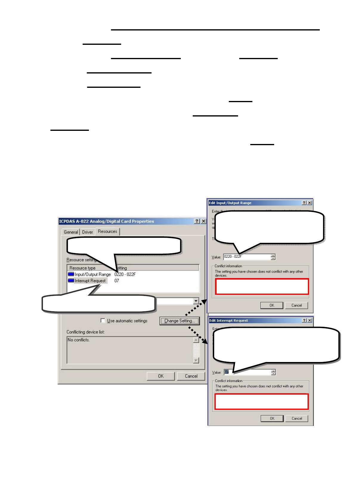
8. Modify the device properties
9. Reboot the PC
The detail “add hardware” information.
please refer to
CD:\NAPDOS\ISA\Manual\PCI_ISA_PnP_Driver_Installation_in_Win9x_2K_XP.pdf
1.
Select Input/Output Range
3.
Select Interrupt Request
No devices are conflicting
2
.
Click “Change Setting” to
change I/O Range (Depend on
I/O Base Address)
4
.
Click “Change Setting” to change
Interrupt Request. (Depend on
Interrupt Level setting)
- 5 -
………………………………………………
Pin Assignments
6
Pin
Description
Pin
Description
1 PC7 2 GND
3 PC6 4 GND
5 PC5 6 GND
7 PC4 8 GND
9 PC3 10 GND
11 PC2 12 GND
13 PC1 14 GND
15 PC0 16 GND
17 PB7 18 GND
19 PB6 20 GND
21 PB5 22 GND
23 PB4 24 GND
25 PB3 26 GND
27 PB2 28 GND
29 PB1 30 GND
31 PB0 32 GND
33 PA7 34 GND
35 PA6 36 GND
37 PA5 38 GND
39 PA4 40 GND
41 PA3 42 GND
43 PA2 44 GND
45 PA1 46 GND
47 PA0 48 GND
49 +5V 50 GND
C
H0/1/2/3/4/5:50
-
pin header
CH5:The DIO-144 only
TTL
High(1)
2.4V ~5.0V
(Voltages over 5.0V will
damage the device)
None
Defined
2.4V~0.8V
TTL
Low(0)
Under 0.8V
All signal are TTL compatible
compatible
- 6 -
………………………………………………
Self-Test
I. Use CA-5002(Optional) to connect the CH0 with
CH1.
II. Run the DIO sample program.
Get the file from(default path):
C:\DAQPro\DIO_WinXXX\Demo\
III. Check number of the DIO-96/144, and test DIO
function
Please follow those steps:
7
C
H2
3
C
H1
2
C
H0
C
H3
4
C
H4
34
C
H5
(DIO-144 only)
- 7 -
Step
1
Step 2
Step 3
Step 4
Step 5
One DIO-96/144 card had successfully installed to PC
Select the board number for the
DIO
-
96/144
.
It s
tart
s
fro
m 0.
Select th
e Ch No. to 1
Click this
button to
output the value
Click this
button to input the value
Step 6
Check
the port A,B and C value.
If port A is 0, port B is FF and port C is 55.
The Test is pass!!!
Complet
1
2
4
5
3
6
- 8 -
………………………………………………
Additional Information
DIO-96/144 Series Card Product page:
http://www.icpdas.com/products/DAQ/pc_based/dio_96&144.htm
DN-37(Optional) page:
http://www.icpdas.com/products/DAQ/screw_terminal/dn_37.htm
ADP-37(Optional) page:
http://www.icpdas.com/products/DAQ/screw_terminal/adp_xx.htm
Documents:
CD:\NAPDOS\ISA\DIO\manual
CD:\NAPDOS\ISA\Manual
http://ftp.icpdas.com/pub/cd/iocard/isa/napdos/isa/DIO/manual/
Software:
CD:\ ISA\NAPDOS\ISA\DIO
http://www.icpdas.com/download/isa/dio/index.htm
The ICP DAS Web Site
http://www.icpdas.com
Contact Us
Service@icpdas.com
Copyright ©2008 by ICP DAS Co., Ltd. All right are reserved
8
Technical support
Supplies and ordering information
Ways to enhance your device
FAQ
Application story
  • Page 1 1
  • Page 2 2
  • Page 3 3
  • Page 4 4
  • Page 5 5
  • Page 6 6
  • Page 7 7
  • Page 8 8

ICP DIO-144 Quick Start

Type
Quick Start
This manual is also suitable for

Ask a question and I''ll find the answer in the document

Finding information in a document is now easier with AI

in other languages