Page is loading ...

MINI-MICRO ™ iLUME™
Flush Mount Installation
RELEASED
11-21-16
REFERENCE NUMBER
INS001080.2
40429 Brickyard Drive • Madera, CA 93636 • USA
559.438.5800 • FAX 559.438.5900
www.bklighting.com • [email protected]
B-K LIGHTING
THIS DOCUMENT CONTAINS PROPRIETARY INFORMATION OF B-K LIGHTING, INC. AND ITS RECEIPT OR POSSESSION DOES NOT CONVEY ANY RIGHTS TO REPRODUCE, DISCLOSE ITS CONTENTS, OR TO MANUFACTURE, USE OR SELL ANYTHING IT MAY
DESCRIBE. REPRODUCTION, DISCLOSURE OR USE WITHOUT SPECIFIC WRITTEN AUTHORIZATION OF B-K LIGHTING, INC. IS STRICTLY FORBIDDEN.
NEEDED
FOR
INSTALLATION:
5/64” Allen Wrench
Waterproof Wire Connectors
2-1/4” Drill Bit and Drill
Warning Flammable Hot Surface
Faceplate
Body
18 gauge wire
Epoxy
Flush mount collar
• Product must be installed by a qualified person in a manner
consistent with its intended use and in compliance with the
National Electrical Code, Canadian Electrical Code, and all Local
and Provincial Codes.
• Follow product label information and instructions.
• Qualified Personnel must perform all servicing or relamping of
this product.
• Before wiring to power supply and during servicing or relamping,
turn off power at fuse or circuit breaker before service.
• The use of accessory equipment not recommended by the
manufacturer or installed contrary to instructions may cause an
unsafe condition. The use of damaged components may cause
an unsafe condition and void product warranty.
IMPORTANT SAFETY INFORMATION - READ, FOLLOW, AND SAVE ALL SAFETY
AND INSTALLATION INSTRUCTIONS
• Do not block light emanating from product in whole or part,
as this may cause an unsafe condition.
• Never operate the fixture with missing or damaged lens.
Lens must be cleaned on regular basis.
• Entire fixture may become extremely hot. Do not touch hot
lens or fixture body. Do not touch the lamp at any time. Use
a clean, dry, soft cloth to handle the lamp. Oil from skin may
damage the lamp and cause it to rupture.
• Replace lamp only with correct wattage and type of lamp
marked on fixture label.
• All gaskets, o-rings and sealing surfaces must be kept clean
during installation and service; failure to do this may cause an
unsafe condition and void product warranty.
INSTRUCTIONS PERTAINING TO
A RISK OF FIRE, OR INJURY TO
PERSONS IMPORTANT SAFETY
INSTRUCTIONS
Lighted lamp is HOT!
WARNING - To reduce the risk of FIRE OR INJURY TO PERSONS:
Turn off/unplug and allow to cool before replacing lamp.
Lamp gets HOT quickly! Contact only switch/plug when
turning on.
Do not touch hot lens, guard, or enclosure (see diagram/
picture).
Keep lamp away from materials that may burn.
Do no touch the lamp at any time. Use a soft cloth. Oil
from skin may damage lamp.
Do not operate the luminaire fitting with a missing or
damaged shield.
SAVE THESE INSTRUCTIONS
By Others
· Suitable for wet locations · Not suitable for through wiring
IMPORTANT LISTINGS AND CERTIFICATIONS
IMPORTANT SAFETY INFORMATION - READ, FOLLOW, AND SAVE THESE INSTALLATION INSTRUCTIONS
Please refer to the low voltage design guide at www.bklighting.com/lvguide before installation for proper wire selection.

RELEASED
11-21-16
REFERENCE NUMBER
INS001080.2
40429 Brickyard Drive • Madera, CA 93636 • USA
559.438.5800 • FAX 559.438.5900
www.bklighting.com • [email protected]
B-K LIGHTING
PROJECT:
TYPE:
MINI-MICRO ™ iLUME™
Flush Mount Installation
Align holes
with window
orientation
2 window
faceplate
shown
4. Fit flush mount collar into hole so it is flush with
finished surface. Wipe off any excess adhesive.
NOTE: The optical opening on faceplate will
align with the threaded holes in the flush
mount collar.
2 window
faceplate
shown
Finished grade
8 3/4”
LINE
12V
FIXTURE
COM
Remote
Transformer
COM
2 window
faceplate
shown
Optical opening on
faceplate will align with
alignment arrows on
temporary cover
Optical opening on
faceplate will align with
alignment arrows on
temporary cover
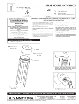
Stability flange
Rebar or stake (by others)
Pea gravel or sand
Finished grade
Concrete
Finished grade
Concrete
8. Remove temporary cover and pull out low
voltage wire.
Wire nuts must
clear opening
6”
min.
Finished grade
6”
min.
Finished grade
Wire nuts must
clear opening
6”
min.
Finished grade
8 3/4”
5. Supply low voltage wiring necessary for
installation (By Others). Loop minimum of 6” of
low voltage wire behind mounted collar to allow
for fixture service.
NOTE: Leave sufficient wire length in hole for
future service.
IMPORTANT SAFETY INFORMATION LISTED ON REVERSE
READ, FOLLOW, AND SAVE ALL SAFETY AND INSTALLATION INSTRUCTIONS
Align holes
with window
orientation
2 window
faceplate
shown
7. Mount faceplate to collar using (2) #6-32 x 5/8”
flat head cap screws (provided) with 5/64” Allen
wrench.
2 window
faceplate
shown
Finished grade
8 3/4”
LINE
12V
FIXTURE
COM
Remote
Transformer
COM
2 window
faceplate
shown
Optical opening on
faceplate will align with
alignment arrows on
temporary cover
Optical opening on
faceplate will align with
alignment arrows on
temporary cover
Stability flange
Rebar or stake (by others)
Pea gravel or sand
Finished grade
Concrete
Finished grade
Concrete
8. Remove temporary cover and pull out low
voltage wire.
Wire nuts must
clear opening
6”
min.
Finished grade
6”
min.
Finished grade
Wire nuts must
clear opening
6”
min.
Finished grade
8 3/4”
6. Pull low voltage wire through flush mount collar
and make two low voltage connections using
proper wire connectors (By Others). Insert wires
and fixture back into hole.
Finished grade
8 3/4”
2 window
faceplate
shown
Finished grade
8 3/4”
LINE
12V
FIXTURE
COM
Remote
Transformer
COM
2 window
faceplate
shown
Optical opening on
faceplate will align with
alignment arrows on
temporary cover
Optical opening on
faceplate will align with
alignment arrows on
temporary cover
Stability flange
Rebar or stake (by others)
Pea gravel or sand
Finished grade
Concrete
Stability flange
Rebar or stake (by others)
Pea gravel or sand
Finished grade
Concrete
WIRING DIAGRAM
Align holes
with window
orientation
2 window
faceplate
shown
Align holes
with window
orientation
2 window
faceplate
shown
Align holes
with window
orientation
2 window
faceplate
shown
1. Drill 2-1/4” diameter hole, 3” deep minimum, for
fixture.
2. Prepare epoxy according to instructions on
packaging.
3. Use mixing stick to apply the epoxy to the interior
of the 2-1/4” hole as shown.

RELEASED
11-21-16
REFERENCE NUMBER
INS001080.2
40429 Brickyard Drive • Madera, CA 93636 • USA
559.438.5800 • FAX 559.438.5900
www.bklighting.com • [email protected]
B-K LIGHTING
IMPORTANT SAFETY INFORMATION LISTED ON REVERSE
READ, FOLLOW, AND SAVE ALL SAFETY AND INSTALLATION INSTRUCTIONS
PROJECT:
TYPE:
MINI-MICRO ™ iLUME™
Flush Mount Installation
THIS PRODUCT IS AVAILABLE WITH A FACTORY INSTALLED LED.
1. Loosen #8-32 set screw on faceplate assembly
using a 5/64” Allen wrench and remove.
Loosen set screw on collar and remove.
COMPONENT REPLACEMENT - IF REQUIRED
2. Pull the heat sink from the body to expose
the LED board and Driver components.
Utilize quick disconnects to change modular
LED and driver components. Re-install the
heat sink into body.
3. Replace faceplate assembly and tighten set
screw. Re-Install fixture.
Finished grade
8 3/4”
2 window
faceplate
shown
Finished grade
8 3/4”
LINE
12V
FIXTURE
COM
Remote
Transformer
COM
2 window
faceplate
shown
Optical opening on
faceplate will align with
alignment arrows on
temporary cover
Optical opening on
faceplate will align with
alignment arrows on
temporary cover
Stability flange
Rebar or stake (by others)
Pea gravel or sand
Finished grade
Concrete
Stability flange
Rebar or stake (by others)
Pea gravel or sand
Finished grade
Concrete
Faceplate
BKSSL
Power Pipe™
Collar
Stability Flange
Body
Power Pipe™
Surface mount collar
Stability Flange
Temporary cover
Finished grade
8 3/4”
2 window
faceplate
shown
Finished grade
8 3/4”
LINE
12V
FIXTURE
COM
Remote
Transformer
COM
2 window
faceplate
shown
Optical opening on
faceplate will align with
alignment arrows on
temporary cover
Optical opening on
faceplate will align with
alignment arrows on
temporary cover
Stability flange
Rebar or stake (by others)
Pea gravel or sand
Finished grade
Concrete
Stability flange
Rebar or stake (by others)
Pea gravel or sand
Finished grade
Concrete
Faceplate
BKSSL
Power Pipe™
Collar
Stability Flange
Body
Power Pipe™
Surface mount collar
Stability Flange
Temporary cover
/