Page is loading ...

SSAAFFEETTYY WWAARRNNIINNGG
Only qualified personnel should install and service the equipment. The installation, starting up, and servicing of heating, ventilating, and
air-conditioning equipment can be hazardous and requires specific knowledge and training. Improperly installed, adjusted or altered
equipment by an unqualified person could result in death or serious injury. When working on the equipment, observe all precautions in the
literature and on the tags, stickers, and labels that are attached to the equipment.
October 2014 11-BC37D1-1D-EN
Variable Speed AccuLink™™ System
Heat Pumps and Air Conditioners
4A6V8024A1000A
4A6V8036A1000A
4A6V8037A1000A
4A6V8048A1000A
4A6V8049A1000A
4A6V8060A1000A
4A7V8024A1000A
4A7V8036A1000A
4A7V8037A1000A
4A7V8048A1000A
4A7V8060A1000A
Scan to see help
videos on this
product
NNoottee:: “Graphics in this document are for representation
only. Actual model may differ in appearance.”
Installer’s Guide

©2014 American Standard Heating & Air Conditioning 11-BC37D1-1D-EN
SAFETY SECTION — OUTDOOR
IImmppoorrttaanntt — This document contains a wiring diagram
and service information. This is customer property and
is to remain with this unit. Please return to service
information pack upon completion of work.
WWAARRNNIINNGG
HHAAZZAARRDDOOUUSS VVOOLLTTAAGGEE!!
FFaaiilluurree ttoo ffoollllooww tthhiiss WWaarrnniinngg ccoouulldd rreessuulltt iinn
pprrooppeerrttyy ddaammaaggee,, sseevveerree ppeerrssoonnaall iinnjjuurryy,, oorr ddeeaatthh..
DDiissccoonnnneecctt aallll eelleeccttrriicc ppoowweerr,, iinncclluuddiinngg rreemmoottee
ddiissccoonnnneeccttss bbeeffoorree sseerrvviicciinngg.. FFoollllooww pprrooppeerr
lloocckkoouutt//ttaaggoouutt pprroocceedduurreess ttoo eennssuurree tthhee ppoowweerr
ccaannnnoott bbee iinnaaddvveerrtteennttllyy eenneerrggiizzeedd..
WWAARRNNIINNGG
RREEFFRRIIGGEERRAANNTT OOIILL!!
AAnnyy aatttteemmpptt ttoo rreeppaaiirr aa cceennttrraall aaiirr ccoonnddiittiioonniinngg
pprroodduucctt mmaayy rreessuulltt iinn pprrooppeerrttyy ddaammaaggee,, sseevveerree
ppeerrssoonnaall iinnjjuurryy,, oorr ddeeaatthh..
TThheessee uunniittss uussee RR--441100AA rreeffrriiggeerraanntt wwhhiicchh ooppeerraatteess
aatt 5500 ttoo 7700%% hhiigghheerr pprreessssuurreess tthhaann RR--2222.. UUssee oonnllyy
RR--441100AA aapppprroovveedd sseerrvviiccee eeqquuiippmmeenntt.. RReeffrriiggeerraanntt
ccyylliinnddeerrss aarree ppaaiinntteedd aa ““RRoossee”” ccoolloorr ttoo iinnddiiccaattee
tthhee ttyyppee ooff rreeffrriiggeerraanntt aanndd mmaayy ccoonnttaaiinn aa ““ddiipp””
ttuubbee ttoo aallllooww ffoorr cchhaarrggiinngg ooff lliiqquuiidd rreeffrriiggeerraanntt iinnttoo
tthhee ssyysstteemm.. AAllll RR--441100AA ssyysstteemmss wwiitthh vvaarriiaabbllee
ssppeeeedd ccoommpprreessssoorrss uussee aa PPVVEE ooiill tthhaatt rreeaaddiillyy
aabbssoorrbbss mmooiissttuurree ffrroomm tthhee aattmmoosspphheerree.. TToo lliimmiitt
tthhiiss ““hhyyggrroossccooppiicc”” aaccttiioonn,, tthhee ssyysstteemm sshhoouulldd
rreemmaaiinn sseeaalleedd wwhheenneevveerr ppoossssiibbllee.. IIff aa ssyysstteemm hhaass
bbeeeenn ooppeenn ttoo tthhee aattmmoosspphheerree ffoorr mmoorree tthhaann 44
hhoouurrss,, tthhee ccoommpprreessssoorr ooiill mmuusstt bbee rreeppllaacceedd.. NNeevveerr
bbrreeaakk aa vvaaccuuuumm wwiitthh aaiirr aanndd aallwwaayyss cchhaannggee tthhee
ddrriieerrss wwhheenn ooppeenniinngg tthhee ssyysstteemm ffoorr ccoommppoonneenntt
rreeppllaacceemmeenntt..
CCAAUUTTIIOONN
HHOOTT SSUURRFFAACCEE!!
MMaayy ccaauussee mmiinnoorr ttoo sseevveerree bbuurrnniinngg.. FFaaiilluurree ttoo
ffoollllooww tthhiiss CCaauuttiioonn ccoouulldd rreessuulltt iinn pprrooppeerrttyy
ddaammaaggee oorr ppeerrssoonnaall iinnjjuurryy..
DDoo nnoott ttoouucchh ttoopp ooff ccoommpprreessssoorr..
CCAAUUTTIIOONN
CCOONNTTAAIINNSS RREEFFRRIIGGEERRAANNTT!!
FFaaiilluurree ttoo ffoollllooww pprrooppeerr pprroocceedduurreess ccaann rreessuulltt iinn
ppeerrssoonnaall iillllnneessss oorr iinnjjuurryy oorr sseevveerree eeqquuiippmmeenntt
ddaammaaggee..
SSyysstteemm ccoonnttaaiinnss ooiill aanndd rreeffrriiggeerraanntt uunnddeerr hhiigghh
pprreessssuurree.. RReeccoovveerr rreeffrriiggeerraanntt ttoo rreelliieevvee pprreessssuurree
bbeeffoorree ooppeenniinngg ssyysstteemm..
CCAAUUTTIIOONN
GGRROOUUNNDDIINNGG RREEQQUUIIRREEDD!!
FFaaiilluurree ttoo iinnssppeecctt oorr uussee pprrooppeerr sseerrvviiccee ttoooollss mmaayy
rreessuulltt iinn eeqquuiippmmeenntt ddaammaaggee oorr ppeerrssoonnaall iinnjjuurryy..
RReeccoonnnneecctt aallll ggrroouunnddiinngg ddeevviicceess.. AAllll ppaarrttss ooff tthhiiss
pprroodduucctt tthhaatt aarree ccaappaabbllee ooff ccoonndduuccttiinngg eelleeccttrriiccaall
ccuurrrreenntt aarree ggrroouunnddeedd.. IIff ggrroouunnddiinngg wwiirreess,, ssccrreewwss,,
ssttrraappss,, cclliippss,, nnuuttss,, oorr wwaasshheerrss uusseedd ttoo ccoommpplleettee aa
ppaatthh ttoo ggrroouunndd aarree rreemmoovveedd ffoorr sseerrvviiccee,, tthheeyy mmuusstt
bbee rreettuurrnneedd ttoo tthheeiirr oorriiggiinnaall ppoossiittiioonn aanndd pprrooppeerrllyy
ffaasstteenneedd..
WWAARRNNIINNGG
SSEERRVVIICCEE VVAALLVVEESS!!
FFaaiilluurree ttoo ffoollllooww tthhiiss wwaarrnniinngg wwiillll rreessuulltt iinn aabbrruupptt
rreelleeaassee ooff ssyysstteemm cchhaarrggee aanndd mmaayy rreessuulltt iinn
ppeerrssoonnaall iinnjjuurryy aanndd//oorr pprrooppeerrttyy ddaammaaggee..
EExxttrreemmee ccaauuttiioonn sshhoouulldd bbee eexxeerrcciisseedd wwhheenn
ooppeenniinngg tthhee LLiiqquuiidd LLiinnee SSeerrvviiccee VVaallvvee.. TTuurrnn vvaallvvee
sstteemm ccoouunntteerrcclloocckkwwiissee oonnllyy uunnttiill tthhee sstteemm
ccoonnttaaccttss tthhee rroolllleedd eeddggee.. NNoo ttoorrqquuee iiss rreeqquuiirreedd..
WWAARRNNIINNGG
BBRRAAZZIINNGG RREEQQUUIIRREEDD!!
FFaaiilluurree ttoo iinnssppeecctt lliinneess oorr uussee pprrooppeerr sseerrvviiccee ttoooollss
mmaayy rreessuulltt iinn eeqquuiippmmeenntt ddaammaaggee oorr ppeerrssoonnaall
iinnjjuurryy..
iiff uussiinngg eexxiissttiinngg rreeffrriiggeerraanntt lliinneess mmaakkee cceerrttaaiinn tthhaatt
aallll jjooiinnttss aarree bbrraazzeedd,, nnoott ssoollddeerreedd..
WWAARRNNIINNGG
HHIIGGHH LLEEAAKKAAGGEE CCUURRRREENNTT!!
FFaaiilluurree ttoo ffoollllooww tthhiiss WWaarrnniinngg ccoouulldd rreessuulltt iinn
pprrooppeerrttyy ddaammaaggee,, sseevveerree ppeerrssoonnaall iinnjjuurryy,, oorr ddeeaatthh..
EEaarrtthh ccoonnnneeccttiioonn eesssseennttiiaall bbeeffoorree ccoonnnneeccttiinngg
eelleeccttrriiccaall ssuuppppllyy..

11-BC37D1-1D-EN 3
+VDC -VDC
ELECTRICAL HAZARD
Failure to follow this warning
coul d result in personal
injury or death.
WAIT TWO (2) MINUTES
after disconnecting power
prior to touching electrical
components as they may
hol d a dangerous charge of
400VDC, then verify DC
Voltage is less than 42 VDC at
inverter test points labeled
+VDC and -VDC befor e
ser vicing board.
400 VOLTS
WARNING
+ VDC
and
- VDC
CAUTION - HOT SURFACE
Approved Combinations for Variable Speed Units
• AZONE 850 Comfort Control, or AZONE 950 with Software Version
3.0 or Higher
• TAM8C or later models
• Platinum SV Furnace
• Platinum ZV Furnace
• Approved System Accessories
Note: See AHRI directory for approved indoor and outdoor model
combinations. Only Trane coils and air handlers are approved
for use with variable speed outdoor units.
Scan to see an
overview video
about the IVSC
Board
Table 1. Operating Range
Cooling 55°F to 120°F
Heating -10°F to 66°F
SSAAFFEETTYY SSEECCTTIIOONN —— OOUUTTDDOOOORR

411-BC37D1-1D-EN
Unit Location Considerations . . . . . . . . . . . . . . . 5
......................................... 6
Coastal Considerations . . . . . . . . . . . . . . . . 7
Unit Preparation . . . . . . . . . . . . . . . . . . . . . . . . . . . . 8
Setting Up the Unit . . . . . . . . . . . . . . . . . . . . . . . 8
Refrigerant Line Considerations . . . . . . . . . . . . 9
Refrigerant Line Brazing . . . . . . . . . . . . . . . . . . . 12
Refrigerant Line Leak Check . . . . . . . . . . . . . . . 14
Refrigerant Line and Indoor Coil
Evacuation . . . . . . . . . . . . . . . . . . . . . . . . . . . . . . 14
Charging: Weigh-In Method . . . . . . . . . . . . . . . 15
Service Valves . . . . . . . . . . . . . . . . . . . . . . . . . . . . . 16
Electrical — Low Voltage . . . . . . . . . . . . . . . . . . 17
Electrical — High Voltage . . . . . . . . . . . . . . . . . . 18
Integrated Variable Speed Control Board
LED Indicators . . . . . . . . . . . . . . . . . . . . . . . . . . . . . 19
Start Up . . . . . . . . . . . . . . . . . . . . . . . . . . . . . . . . . . . 20
System Charge Adjustment . . . . . . . . . . . . . . . 21
Subcool Charging Correction Charts. . . . . . . 22
Refrigerant Charging Chart . . . . . . . . . . . . . . . 22
Charging the Unit. . . . . . . . . . . . . . . . . . . . . . . . . . 23
Communicating Display Assembly
(CDA). . . . . . . . . . . . . . . . . . . . . . . . . . . . . . . . . . . . . . 25
Defrost Control (Heat Pump only). . . . . . . . . . 26
Checkout Procedures . . . . . . . . . . . . . . . . . . . . . . 27
Table of Contents

11-BC37D1-1D-EN 5
Unit Location Considerations
Table 2. Unit Dimensions and Weight
Models H x D x W (in) Weight * (lb)
D
H
W
4A6V8024A 41 x 30 x 33 195
4A6V8036A 41 x 30 x 33 208
4A6V8037A 41 x 34 x 37 229
4A6V8048A 41 x 34 x 37 234
4A6V8049A 41 x 34 x 37 241
4A6V8060A 45 x 34 x 37 250
4A7V8024A 41 x 30 x 33 196
4A7V8036A 41 x 30 x 33 207
4A7V8037A 41 x 34 x 37 225
4A7V8048A 41 x 34 x 37 245
4A7V8060A 45 x 34 x 37 250
* Weight values are estimated (uncrated).
• When mounting the outdoor unit on a roof, be sure the roof will
support the unit’s weight.
• Properly selected isolation is recommended to alleviate sound or
vibration transmission to the building structure.
Table 3. Refrigerant Line and Service Valve Connection Sizes
Model
Rated Line Sizes Service Valve
Connection Sizes
50’
Max
Line
Lift
Sta ndard
Line Set
150’ Max
Line Length
50
Max
Line
Lift
100’ Max
Line
Length
100’ Max
Line
Length
Refer to (a), (b), and (c) footnotes for
specific model details
Vapor
Line
Liquid
Line
Vapor Line
Connection
Liquid Line
Connection
4A6V8024A 5/8 (a) 3/8 5/8 3/8
4A6V8036A 3/4 3/8 3/4 3/8
4A6V8037A 3/4 3/8 3/4 3/8
4A6V8048A 7/8 3/8 7/8 3/8
4A6V8049A 7/8 3/8 7/8 3/8
4A6V8060A 1—1/8 (b) 3/8 7/8 3/8
4A7V8024A 5/8 3/8 5/8 3/8
4A7V8036A 3/4 3/8 3/4 3/8
4A7V8037A 3/4 3/8 3/4 3/8
4A7V8048A 7/8 3/8 7/8 3/8
4A7V8060A 1—1/8 (c) 3/8 7/8 3/8
(a) The max length of refrigerant lines from outdoor to indoor unit MUST NOT exceed 150 feet. The max vertical change MUST NOT exceed 50 feet.
(b) The max length of refrigerant lines from the outdoor to indoor unit MUST NOT exceed 80 feet. The max vertical change MUST NOT exceed 10 feet.
(c) The max length of refrigerant lines from outdoor to indoor unit MUST NOT exceed 80 feet. The max vertical change MUST NOT exceed 25 feet.

611-BC37D1-1D-EN
Table 4. Alternate Refrigerant Line and Service Valve Connection Sizes
Model
Alternate Line Sizes Service Valve
Connection Sizes
Vapor
Line
Liquid
Line
Vapor Line
Connection
Liquid Line
Connection
4A6V8024A 3/4" (a) 5/16" 5/8" 3/8"
4A6V8036A 5/8" (a) 5/16" 3/4" 3/8"
7/8" (b) 5/16" 3/4" 3/8"
4A6V8037A 5/8" (a) 5/16" 3/4" 3/8"
7/8" (b) 5/16" 3/4" 3/8"
4A6V8048A 3/4" (a) 3/8" 7/8" 3/8"
4A6V8049A 3/4" (a) 3/8" 7/8" 3/8"
4A6V8060A 3/4" (a) 3/8" 7/8" 3/8"
7/8" (a) 3/8" 7/8" 3/8"
Model
Alternate Line Sizes Service Valve
Connection Sizes
Vapor
Line
Liquid
Line
Vapor Line
Connection
Liquid Line
Connection
4A7V8024A 3/4" (a) 5/16" 5/8" 3/8"
4A7V8036A 5/8" (a) 5/16" 3/4" 3/8"
7/8" (b) 5/16" 3/4" 3/8"
4A7V8048A 3/4" (a) 3/8" 7/8" 3/8"
4A7V8060A 3/4" (a) 3/8" 7/8" 3/8"
7/8" (a) 3/8" 7/8" 3/8"
(a) The max length of refrigerant lines from outdoor to indoor unit MUST NOT exceed 150 feet. The max vertical change MUST NOT exceed 50 feet.
(b) The max length of refrigerant lines from outdoor to indoor unit MUST NOT exceed 80 feet. The max vertical change MUST NOT exceed 25 feet.
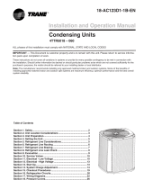
UUnniitt LLooccaattiioonn CCoonnssiiddeerraattiioonnss

11-BC37D1-1D-EN 7
Table 5. Suggested Locations for Best Reliability
• Ensure the top discharge area is unrestricted for at least 5
feet above the unit.
• Provide at least 3 feet clearance in front of the control box
(access panels) and any other side requiring service.
• Do not locate close to bedrooms as operational sounds may
be objectionable.
• Avoid locations near windows and similar areas where
condensation and freezing defrost vapor can annoy a
customer.
• Position the outdoor unit a minimum of 12” from any wall or
surrounding shrubbery to ensure adequate airflow.
• Outdoor unit location must be far enough away from any
structure to prevent excess roof runoff water or icicles from
falling directly on the unit.
• Position the outdoor unit a minimum of 12” from any wall or
surrounding shrubbery to ensure adequate airflow.
• Outdoor unit location must be far enough away from any
structure to prevent excess roof runoff water or icicles from
falling directly on the unit.
Min. 12” to
Shrubbery
Avoid Install
Near Bedrooms
Min 5’ Unrestricted
Access Panel
Min 3’
Unrestricted
Min. 12” to
Shrubbery Min. 12”
to Wall
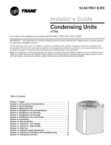
Table 6. Cold Climate Considerations (Heat Pump Only)
Note: It is recommended that these precautions be taken for
units being installed in areas where snow accumulation and
prolonged below-freezing temperatures occur.
• Units should be elevated 3–12 inches above the pad or
rooftop, depending on local weather. This additional height
will allow drainage of snow and ice melted during defrost cycle
prior to its refreezing. Ensure that drain holes in unit base pan
are not obstructed, preventing drainage of defrost water.
• If possible, avoid locations that are likely to accumulate snow
drifts. If not possible, a snow drift barrier should be installed
around the unit to prevent a build-up of snow on the sides of
the unit.
Min. 12”
Snow
Barrier
3-12” Elevation
Snow L egs
Pad
Coastal Considerations
If installed within one mile of salt water, including seacoasts and inland waterways, models without factory supplied Seacoast Salt Shields
require the addition of BAYSEAC001 (Seacoast Kit) at installation time.
UUnniitt LLooccaattiioonn CCoonnssiiddeerraattiioonnss

811-BC37D1-1D-EN
Unit Preparation
1. Check for damage and report promptly to the carrier
any damage found to the unit.
2. To remove the unit from the pallet, remove tabs by
cutting with a sharp tool.
Setting Up the Unit
Table 7. Pad Installation
When installing the unit on a support pad, such as a concrete slab,
consider the following:
• The pad should be at least 1” larger than the unit on all sides.
• The pad must be separate from any structure.
• The pad must be level.
• The pad should be high enough above grade to allow for drainage.
• The pad location must comply with National, State, and Local
codes.

11-BC37D1-1D-EN 9
Refrigerant Line Considerations
Table 8. Required Refrigerant Line Length
Determine required line length and lift. You will need this to determine
the subcooling charging corrections later in the installation process.
Total Line Length = ___________________________Ft.
Total Vertical Change (lift) = ____________________Ft.
Line Length
Table 9. Refrigerant Line Insulation
Important: The Vapor Line must always be insulated. DO NOT allow
the Liquid Line and Vapor Line to come in direct (metal to
metal) contact.
Note: The gas line must always be insulated. Insulating the liquid line
through attic spaces may benefit system performance by
minimizing heat gain in the liquid line.
Liquid Li ne Vapor Line
Insulati on

10 11-BC37D1-1D-EN
Table 10. Reuse Existing Refrigerant Lines
CCAAUUTTIIOONN
RREEFFRRIIGGEERRAANNTT!!
FFaaiilluurree ttoo iinnssppeecctt oorr uussee pprrooppeerr sseerrvviiccee ttoooollss mmaayy
rreessuulltt iinn eeqquuiippmmeenntt ddaammaaggee oorr ppeerrssoonnaall iinnjjuurryy..
IIff uussiinngg eexxiissttiinngg rreeffrriiggeerraanntt lliinneess mmaakkee cceerrttaaiinn tthhaatt
aallll jjooiinnttss aarree bbrraazzeedd,, nnoott ssoollddeerreedd..
For retrofit applications, where the existing indoor evaporator coil
and/or refrigerant lines will be used, the following precautions should
be taken.
• Ensure that the indoor evaporator coil and refrigerant lines are
the correct size.
• Ensure that the refrigerant lines are free of leaks, acid, and oil.
Important: For more information, see publication number SS-
APG006–EN
Table 11. Refrigerant Line Routing Precautions
Important: Comply with National, State, and Local Codes when isolating line sets from joists, rafters, walls, or other structural elements.
Important: Take precautions to prevent noise within the building structure due to vibration transmission from the refrigerant lines.
For Example:
• When the refrigerant lines must be fastened to floor joists or other framing in a structure, use isolation type hangers.
• Isolation hangers should also be used when refrigerant lines are run in stud spaces or enclosed ceilings.
• Where the refrigerant lines run through a wall or sill, they should be insulated and isolated.
• Isolate the lines from all duct work.
• Minimize the number of 90°turns.
Table 12. Isolation From Joist/Rafter
8 Feet Maximum
Side View 8 Feet Maximum
Joist/Rafter
Isolator
Line Set
Secure Vapor Line from joists using isolators every 8 ft. Secure Liquid Line directly to insulated Vapor Line using tape, wire, or other appropriate
method every 8 ft.
RReeffrriiggeerraanntt LLiinnee CCoonnssiiddeerraattiioonnss

11-BC37D1-1D-EN 11
Table 13. Isolation In Wall Spaces
Side View
Isolator
Line Set
8 Feet Maximum Wall
8 Feet Maximum
Secure Vapor Line from joists using isolators every 8 ft. Secure Liquid Line directly to insulated Vapor Line using tape, wire, or other appropriate
method every 8 ft.
Table 14. Isolation Through Wall
Wall
Sealant
Insulation
Vapor Line
Duct Work
Isolator
Line Set
DO NOT hang line sets from duct work
RReeffrriiggeerraanntt LLiinnee CCoonnssiiddeerraattiioonnss

12 11-BC37D1-1D-EN
Refrigerant Line Brazing
Table 15. Braze the Refrigerant Lines
1. Remove caps or plugs. Use a deburring tool to debur the pipe
ends. Clean both internal and external surfaces of the tubing
using an emery cloth.
2. Remove the pressure tap cap and valve core from each service
valves.
3. Purge the refrigerant lines and indoor coil with dry nitrogen.

11-BC37D1-1D-EN 13
Table 15. Braze the Refrigerant Lines (continued)
4. Wrap a wet rag around the valve body to avoid heat damage and
continue the dry nitrogen purge.
5. Braze the refrigerant lines to the service valves.
a. For Units shipped with a field-installed external drier, check
liquid line filter drier’s directional flow arrow to confirm
correct direction of refrigeration flow (away from outdoor unit
and toward evaporator coil) as illustrated. Braze the filter
drier to the Liquid Line.
6. Continue the dry nitrogen purge. Do not remove the wet rag until
all brazing is completed.
Important: Remove the wet rag before stopping the dry nitrogen
purge.
Note: Precautions should be taken to avoid heat damage to base pan
during brazing. It is recommended to keep the flame directly
off of the base pan.
3-4” from valve
7. Replace the pressure tap valve cores after the service valves have
cooled.
RReeffrriiggeerraanntt LLiinnee BBrraazziinngg

14 11-BC37D1-1D-EN
Refrigerant Line Leak Check
Table 16. Check for Leaks
1. Pressurize the refrigerant lines and evaporator coil to 150 PSIG
using dry nitrogen.
150 PSIG
2. Check for leaks by using a soapy solution at each brazed location.
Note: Remove nitrogen pressure and repair any leaks before
continuing.
Refrigerant Line and Indoor Coil Evacuation
IImmppoorrttaanntt:: Do not open the service valves until the
refrigerant lines and indoor coil leak check
and evacuation are complete.
1. Evacuate until the micron gauge reads no higher than
350 microns, then close off the valve to the vacuum
pump.
0350
Microns
ON OFF
2. Observe the micron gauge. Evacuation is complete if
the micron gauge does not rise above 500 microns in
one (1) minute.
3. When evacuation is complete, blank off the vacuum
pump and micron gauge, and close the valves on the
manifold gauge set.
1 MIN.

11-BC37D1-1D-EN 15
Charging: Weigh-In Method
Weigh-In Method can be used for the initial installation, or anytime a system charge is being replaced. Weigh-In Method can also be used when
power is not available to the equipment site or operating conditions (indoor/outdoor temperatures) are not in range to verify with the
subcooling charging method.
Table 17. Heat Pumps
AB C D
Model Factory
Charge
Charge
adder for
Indoor Coil
Charge
multiplier for
interconnecting
refrigerant tube
length
024 7 lb. 6 oz. 6 oz. 0.6 oz/ft
036 8 lb. 3 oz. 8 oz. 0.6 oz/ft
037 9 lb. 8 oz. 12 oz. 0.6 oz/ft
048 9 lb. 13 oz. 13 oz. 0.6 oz/ft
049 10 lb. 12 oz. 15 oz. 0.6 oz/ft
060 11 lb. 14 oz. 1 lb., 2 oz. 0.6 oz/ft
Table 18. Air Conditioners
AB C D
Model Factory
Charge
Charge
adder for
Indoor Coil
Charge
multiplier for
interconnecting
refrigerant
tube length
024 7 lb. 6 oz. 6 oz. 0.6 oz/ft
036 7 lb. 14 oz. 7 oz. 0.6 oz/ft
037 9 lb. 6 oz. 12 oz. 0.6 oz/ft
048 11 lb. 1 oz. 1 lb., 0 oz. 0.6 oz/ft
060 11 lb. 14 oz. 1 lb., 2 oz. 0.6 oz/ft
Table 19. New Installations — Calculating Charge using the Weigh-In method
1. Measure in feet the distance between the outdoor unit and the indoor
unit and record on Line 1. Include the entire length of the line from the
service valve to the IDU.
2. Enter the charge multiplier from Column D.
3. Multiply the total length of refrigerant tubing (Line 1) times the value on
Step 2. Record the result on Line 3 of the Worksheet.
4. Locate the outdoor equipment size in Column A. Record the value shown
in Column C of Table 16 for Heat Pumps or Table 17 for Air Conditioners.
5. Add the values from Step 3 and Step 4 and record the resulting value.
This is the amount of refrigerant to weigh-in prior to opening the service
valves.
New Installation Weigh-In Method Worksheet
1. Line Length (ft) ________________________
2. Value from Column D x ________________________
3. Step 1 x Step 2 = ________________________
4. Charge Adder (column C) + ________________________
5. Refrigerant (Steps 3+4) = ________________________
Table 20. Sealed-System Repairs — Calculating Charge using the Weigh-In method.
1. Measure in feet the distance between the outdoor unit and the indoor
unit and record on Line 1. Include the entire length of the line from the
service valve to the IDU.
2. Enter the charge multiplier from Column D.
3. Multiply the total length of refrigerant tubing (Line 1) times the value on
Line 2. Record the result on Line 3 of the Worksheet.
4. Locate the outdoor equipment size in Column A. Record the value shown
in Column C of Table 16 for Heat Pumps or Table 17 for Air Conditioners.
5. Record the value in Column B to Line 5 of the Worksheet.
6. Add the values from Step 3, Step 4, and Step 5 and record the resulting
value on Line 6. This is the amount of refrigerant to weigh-in.
New Installation Weigh-In Method Worksheet
1. Line Length (ft) ________________________
2. Value from Column D x ________________________
3. Step 1 x Step 2 = ________________________
4. Charge Adder (column C) + ________________________
5. Factory Charge (column B) + ________________________
6. Refrigerant (Steps 3+4+5) = ________________________
Note: The only mode approved for setting or validating system charge is using Charging Mode-Cooling. Charging Mode-Cooling is a variable
speed test mode found in the 850/950 comfort control Technician Menu. Outdoor Temperature must be between 55°F and 120°F with
Indoor Temperature kept between 70°F and 80°F.

16 11-BC37D1-1D-EN
Service Valves
Table 21. Open the Gas Service Valve
Important: Leak check and evacuation must be completed before
opening the service valves.
Note: Do not vent refrigerant gases into the atmosphere.
1. Remove valve stem cap.
2. Using a wrench, turn valve stem 1/4 turn counterclockwise to
the fully open position.
3. Replace the valve stem cap to prevent leaks. Tighten finger
tight plus an additional 1/6 turn.
Cap 1/4 Turn Only
Counterclockwise
for Full Open Position
Valve Stem
Unit Side
of Valve
Pressure Tap Port
Gas Line Connection
Table 22. Open the Liquid Service Valve
WWAARRNNIINNGG
SSEERRVVIICCEE VVAALLVVEESS!!
FFaaiilluurree ttoo ffoollllooww tthhiiss wwaarrnniinngg wwiillll rreessuulltt iinn aabbrruupptt
rreelleeaassee ooff ssyysstteemm cchhaarrggee aanndd mmaayy rreessuulltt iinn
ppeerrssoonnaall iinnjjuurryy aanndd//oorr pprrooppeerrttyy ddaammaaggee..
EExxttrreemmee ccaauuttiioonn sshhoouulldd bbee eexxeerrcciisseedd wwhheenn
ooppeenniinngg tthhee LLiiqquuiidd LLiinnee SSeerrvviiccee VVaallvvee.. TTuurrnn vvaallvvee
sstteemm ccoouunntteerrcclloocckkwwiissee oonnllyy uunnttiill tthhee sstteemm
ccoonnttaaccttss tthhee rroolllleedd eeddggee.. NNoo ttoorrqquuee iiss rreeqquuiirreedd..
Important: Leak check and evacuation must be completed before
opening the service valves.
4. Remove service valve cap.
5. Fully insert 3/16” hex wrench into the stem and back out
counterclockwise until valve stem just touches the rolled edge
(approximately five (5) turns).
6. Replace the valve cap to prevent leaks. Tighten finger tight
plus an additional 1/6 turn.
Cap
3/16” Hex Wrench
Rolled Edge to
Captivate Stem
Hex Headed
Valve System
Service Port
Unit Side
of Service
Valve

11-BC37D1-1D-EN 17
Electrical — Low Voltage
Table 23, p. 17defines the size and combined total maximum length of low voltage wiring from the outdoor unit, to the indoor unit, and to the
thermostat.
Note: The use of color coded low voltage wire is recommended to simplify connections between the outdoor unit, the control, and the indoor
unit.
Note: The maximum total cable length for the entire comfort control communicating system is 500 ft. 18 AWG.
Table 23. Low Voltage Maximum Wire Length
CONTROL WIRING
WIRE SIZE MAX. WIRE LENGTH
18 AWG 500 Ft. Combined
Table 24. Low Voltage Hook-up Diagrams
Figure 1. Fully Communicating System
Neatl y bundle all low
voltage wires as shown.
Com municating
Com fort Cont rol
W1
W2
W3
G
Y2
B
O
BK
D
Y1
R
Field wiring
Brown
Blue
Brown
Blue
Red
B - Blue
D - Note 3
D
R
B
Note 1
&
Note 2
Red
Only used for
Load Shed
(Cap off if
not used)
Com m unicating
Indoo r Unit
Note 4
Note 5
Com m unicating Outdoor Unit
1. In communicating mode, unused terminals are non-functional. Do not use.
2. Terminals present will vary by indoor model.
3. “D” is the data line. Installer to select a wire color.
4. If a 3rd party condensate overflow switch is installed, it should be wired in series with R to the thermostat or connected to the External
Switch terminals on the AFC. See External Switch wiring section in the air handler Installer’s Guide.
5. Wire present only on Variable Speed Outdoor Units.
Note: Anti-oxidizing grease is supplied in the documentation package for use when making low voltage field wiring connections at the outdoor
unit. Apply grease to field wiring before installing wire caps to protect these connections from corrosion.

18 11-BC37D1-1D-EN
Electrical — High Voltage
Table 25. High Voltage Power Supply
WWAARRNNIINNGG
LLIIVVEE EELLEECCTTRRIICCAALL CCOOMMPPOONNEENNTTSS!!
FFaaiilluurree ttoo ffoollllooww tthhiiss WWaarrnniinngg ccoouulldd rreessuulltt iinn
pprrooppeerrttyy ddaammaaggee,, sseevveerree ppeerrssoonnaall iinnjjuurryy,, oorr ddeeaatthh..
FFoollllooww aallll eelleeccttrriiccaall ssaaffeettyy pprreeccaauuttiioonnss wwhheenn
eexxppoosseedd ttoo lliivvee eelleeccttrriiccaall ccoommppoonneennttss.. IItt mmaayy bbee
nneecceessssaarryy ttoo wwoorrkk wwiitthh lliivvee eelleeccttrriiccaall ccoommppoonneennttss
dduurriinngg iinnssttaallllaattiioonn,, tteessttiinngg,, sseerrvviicciinngg,, aanndd
ttrroouubblleesshhoooottiinngg ooff tthhiiss pprroodduucctt..
The high voltage power supply must agree with the equipment
nameplate.
Power wiring must comply with national, state, and local codes.
Follow instructions on unit wiring diagram located on the inside of the
control box cover and in the Service Facts document included with the
unit.
Table 26. High Voltage Disconnect Switch
WWAARRNNIINNGG
HHIIGGHH LLEEAAKKAAGGEE CCUURRRREENNTT!!
FFaaiilluurree ttoo ffoollllooww tthhiiss WWaarrnniinngg ccoouulldd rreessuulltt iinn
pprrooppeerrttyy ddaammaaggee,, sseevveerree ppeerrssoonnaall iinnjjuurryy,, oorr ddeeaatthh..
EEaarrtthh ccoonnnneeccttiioonn eesssseennttiiaall bbeeffoorree ccoonnnneeccttiinngg
eelleeccttrriiccaall ssuuppppllyy..
Install a separate disconnect switch at the outdoor unit.
For high voltage connections, flexible electrical conduit is
recommended whenever vibration transmission may create a noise
problem within the structure.
Table 27. High Voltage Disconnect Switch
Ground the outdoor unit per national, state, and local code
requirements.

11-BC37D1-1D-EN 19
Integrated Variable Speed Control Board
LED Indicators
FAN
ALUMINUM COVER PLATE
LSOV EEV
LOAD
MONITOR
TOOL
SHED
CDA
EXT.ODT
PERSONALITY MODULE
STATUS
COMM
T4
T3
T1 T2
HPCO
DATA
CHARGE
SOLENOID
(N/A Phase I)
10
1
18
9J1
J6 J4
DRB
J8
J9
J3
J10
J2
J5
J20
PSC
(not used)
PWM
STATUS
COMM
High
Voltage
to Condensor
The Status (Green) and
COMM (Am ber) LEDs are
located in the upper right
region of the Control
Board.
Fault messages are
displayed on the CDA
LLEEDD’’SS
LED RATE DESCRIP-
TION
INDICA-
TION
STATUS
(GREEN)
SLOW 1 TIME PER
SECOND
STANDBY/
IDLE
MEDIUM 2 TIMES PER
SECOND
CALL FOR
CAPACITY
FAST 5 TIMES PER
SECOND
POWER UP
DELAY
SOLID ON TEST MODE
INTERMITTENT
1 FLASH
EVERY 4
SECONDS
HARD
LOCKOUT
LED RATE DESCRIPTION INDICATION
COMM
(AMBER)
SLOW 1 TIME PER
DEVICE DEVICE COUNT
FAST 5 TIME PER
SECOND
LOSS OF
COMMUNICATION

20 11-BC37D1-1D-EN
Start Up
1. Ensure you have completed the following sections. ”Refrigerant Line Brazing,” p. 12 through ”Electrical — High Voltage,” p. 18
2. Set System Thermostat to OFF.
3. Turn on disconnect(s) to apply power to the indoor and outdoor
units.
ON
OFF
4. Wait 3 hours before starting the unit if the outdoor ambient
temperature is below 85° F.
3 HRS.
5. Run the system using the “Charging Mode-Cooling” test mode
found in the 850/950 comfort control. This is the only approved
method for setting the system charge level by subcooling.
Follow the on-screen prompts.
/